Drawing more Flexible Screw Threads in Fusion 360

After much trial and error and searching for sample code for copying a body multiple times and joining them together, I posted a question to the fusion API and scripts forum here: Copy a Body x times & join them all together - Autodesk Community - Fusion
No response to the problem yet, but it has only been a day. I found one similar that used components and was sort of able to get it to work, but I seem to be missing something.

Meanwhile, I finally was able to get the GuideRail & thread direction in a dropdown input list. Here is what it looks like now.
ThreadTuneDialogDropDown

I also worked out drawing a Bolt & Nut, but am doing that separate for now, to make it simpler to debug.

Next thing I want is a drop-down list at the top to select standard metric threads & fill in the appropriate dialog fields with those.

2 Likes

Here are some links I found for my problem. I just need to study this body joining problem more.

https://adndevblog.typepad.com/manufacturing/2017/08/fusion-360-api-transform-component-.html

https://help.autodesk.com/view/fusion360/ENU/?guid=GUID-153E540B-6246-460C-8B6A-4C58165CEBAA

I added making a bolt & nut to another tab in the dialog box & it all seems to work well so far. I created a comma delimited text file of the metric screw dimensions & added that as a text pull down menu & this will give the user the opportunity to fill out the basic data automatically from the closest standard & change it from there. That is not completely working yet but did get it fill the data in automatically from reading the file. Here is what the dialog looks like so far now with a section showing a bolt & nut drawn with the program.


ThreadTune_Tab2

I got an answer to my question. Turns out the move feature in the API doesn’t support the ability to copy for my case and is broken & he said it needed to be fixed. He gave me a workaround but might be better off making this a component rather than using bodies. Seems like it works for those. I’ll work on it some after I figure out my event handler problem with updating the dialog box when a different metric thread type is selected. Looks like the spur gear python script does what I want. Just need to see how it is done there.

I updated this to v1.1 since I made a lot of changes since last time. The standard metric pulldown works nice now. You select one of the options from M3 - M30 & it fills in 6 of the entries. That way you get the settings set to standard before customizing them to your needs.

After some further thought on the bogging down of the program when generating a sweep using the thread profile & the 2 helix paths, think I have come up with a good solution. I could draw a thread profile for each pitch distance and do the same thing for the helix, then create a separate sweep for each revolution joining each of them together for each sweep. That should get rid of the bogging down. It does not seem like it would change my current code too much either. I tried it manually & seems to work ok.

My 1st couple of thoughts getting around fusion 360 bogging down on the sweep of the helix with a lot of points didn’t work. I did come up with a solution that seems to work. I found a couple of bugs in the process as well as making the helix routine cleaner. I draw a profile for each thread section for the length of the screw & connect them all together as one profile, draw a one revolution helix for the path & guiderail & then sweep all the threads with the single inside revolution helix as the path & the outside helix as the guide. The helix only needs to be one revolution now & therefore makes it a lot less points for fusion to look at. These 2 screen shots should explain visually.


1 Like

I uploaded a new version this morning.

It still has some caveats, but for most normal cases works well. The limitations are probably mostly related to using an approximate helix with spline points. I might try drawing it an AutoCAD style 3D Polyline rather than spline points to see if that is any better. That is essentially the way OpenSCAD does it. I started an Announcement topic on the fusion API & Scripts forums since that seems to be a good place for answers to my limited python experience.
Add-in announcement: Fine-Tune your Screw Thread Designs in Autodesk Fusion. Feedback & ideas welcom… - Autodesk Community - Fusion

1 Like

I updated this again after making all the geometry a component & grouping them on the timeline. Looks a lot simpler on the timeline now.

2 Likes

I get it entirely, even if I can’t use it, and if I understood any of the mechanics of what you have just done I would be even more amazed!

1 Like

I am actually surprised someone else had not done this already as it was not as complicated as I first thought. After looking at what the formula was to create the threads, it did not seem too bad. The most complicated part of the math is just right triangles. Most of my problems have been in learning how the API worked & I still don’t know it that well.

1 Like

I added chamfering to the threads & got rid of the annoying extra tool body left behind when cutting the threads for the Nut.

1 Like

I hate to rely on ChatGPT for some of this code, but this stuff is just too cool & in this case makes it easy.

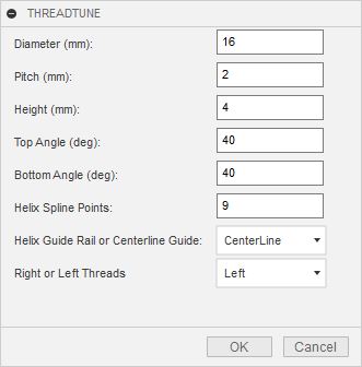
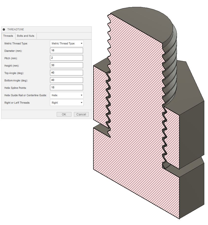
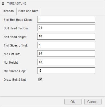
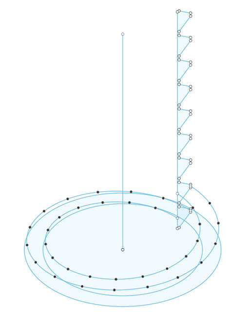
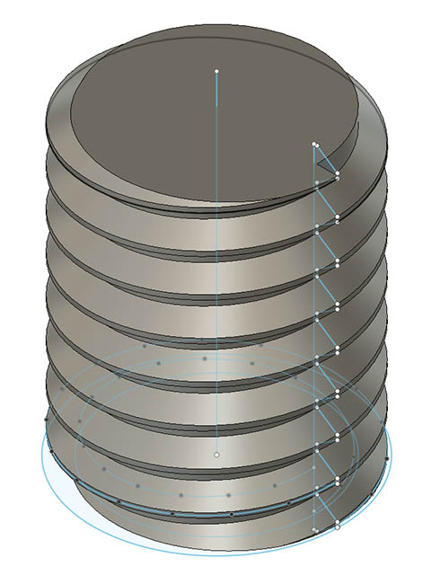
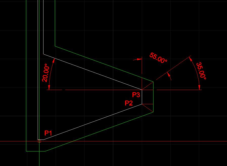
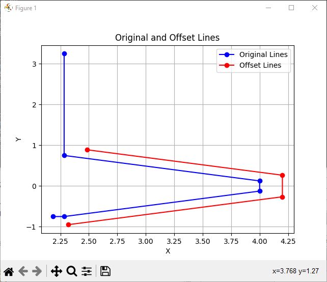
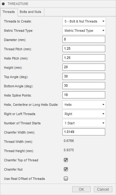
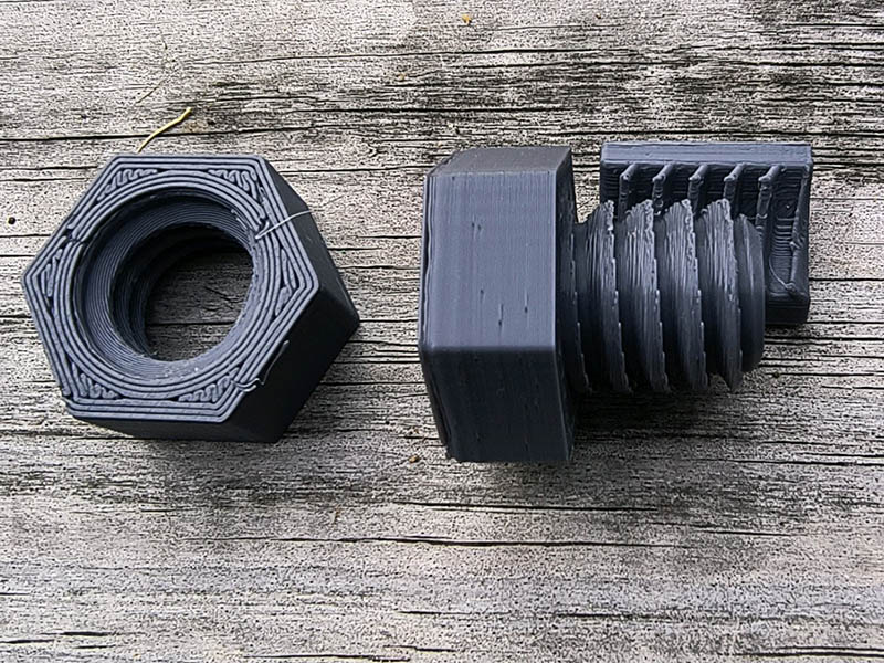
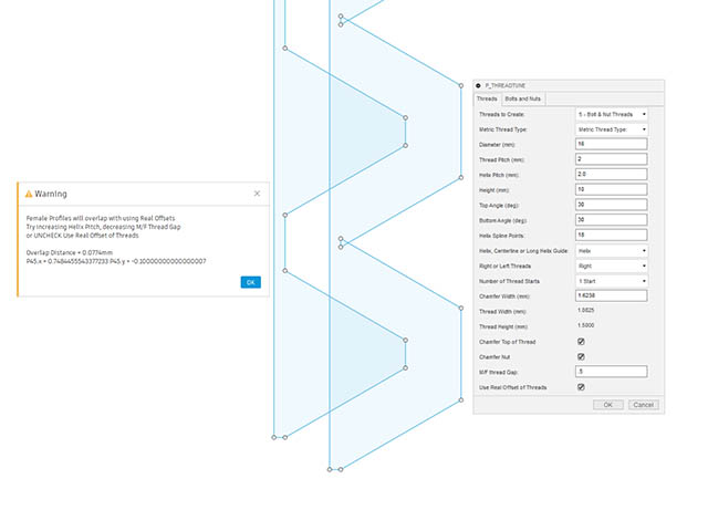
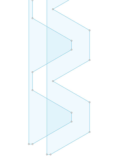
I ran into some issues with changing the pitch to bigger numbers, but if I made the pitch too large, it would not work. Early on in this development, I had wanted to make a true offset of the female threads from the male threads, but with the pitch distance it usually would not work. I decided to unbind that pitch from the helix & made a separate pitch for each. Problem solved, but not quite. How do I calculate those vertex points of the offset lines. I did thread profiles from 15 degrees to 65 degrees to see if I could see a correlation, I could use to get the angle to use with right triangles thinking I could use right triangles to find those points. There does not seem to be a correlation that I can see, so I decided to try ChatGPT to see what it came up with & it was almost perfect. I only had to change the offset distance from positive to negative. Here is an image of the test threads at 20 degrees. The green lines are what I am looking for. I gave it the coordinate points from this 2d drawing, so I could easily test that it works.

In python code, given the points P1 = (0,-.75), P2 = (1.7172,-.125) & P3 = (1.7172,.125) offset 0.2 in the positive direction these 2 lines together and compute the vertex point of the offset line. The vertex point should be X = 1.9172 and Y = -0.2650

import numpy as np

def offset_point(px, py, ox, oy, distance):
    """Offset a point (px, py) in the direction (ox, oy) by a specified distance."""
    norm = np.sqrt(ox**2 + oy**2)
    return (px + distance * ox / norm, py + distance * oy / norm)

def line_intersection(l1, l2):
    """Find the intersection of two lines given by points l1 and l2."""
    xdiff = (l1[0][0] - l1[1][0], l2[0][0] - l2[1][0])
    ydiff = (l1[0][1] - l1[1][1], l2[0][1] - l2[1][1])

    def det(a, b):
        return a[0] * b[1] - a[1] * b[0]

    div = det(xdiff, ydiff)
    if div == 0:
       raise Exception('Lines do not intersect')

    d = (det(*l1), det(*l2))
    x = det(d, xdiff) / div
    y = det(d, ydiff) / div
    return x, y

# Points P1, P2, P3
P1 = (0, -0.75)
P2 = (1.7172, -0.125)
P3 = (1.7172, 0.125)

# Offset distance
offset_distance = 0.2

# Offsetting direction is perpendicular to the line segment direction
def perpendicular_vector(px, py):
    return -py, px

# Offset points for each line
offset_P1 = offset_point(*P1, *perpendicular_vector(P2[0] - P1[0], P2[1] - P1[1]), offset_distance)
offset_P2_1 = offset_point(*P2, *perpendicular_vector(P2[0] - P1[0], P2[1] - P1[1]), offset_distance)
offset_P2_2 = offset_point(*P2, *perpendicular_vector(P3[0] - P2[0], P3[1] - P2[1]), offset_distance)
offset_P3 = offset_point(*P3, *perpendicular_vector(P3[0] - P2[0], P3[1] - P2[1]), offset_distance)

# Find intersection of the two offset lines
vertex_point = line_intersection((offset_P1, offset_P2_1), (offset_P2_2, offset_P3))

print("The vertex point of the offset lines is:", vertex_point)

I gave it all the points I wanted to compute & this time it even plotted the points graphically to show how it looked. That sure makes the tedious coding easy. The vertical offset line does not look visually correct, but the numbers it printed out were.
Here is the image it showed.

2 Likes

Think I am done with adding all the features I wanted to this program. A week or so after initially creating the GitHub repository for this program, I found another repository by the same exact name. I was surprised that GitHub allowed that. I have been thinking about renaming this for a while. In order to keep the name similar, I just changed it to P_ThreadTune with P standing for Python. I will keep the other repository for now with a link to the newer one, but will probably eventually delete it. I might sometime in the future rewrite this in C++ and use the prefix C_ for that. It is fast enough for me, so not sure whether writing it in C++ would be beneficial other than teaching me how to use this API in C++

The dialog box changed considerably since the previous version.

I printed one of these with negative threads on top & positive on the bottom & they do work pretty well. I printed the nut upside down to get rid of the overhangs of the negative threads. They look a little gnarly with the closeup lens & were printed with .2mm layer height. Thanks @azab2c for the link to the video to inspire me to add these to the program.

3 Likes

Nice! Those cleat threads look cool. They seem like something that should print well. Have to try these out now. Thanks for sharing your progress, thought process and results.

1 Like

I have had a problem with the real offset threads that I have known about since using them and initially didn’t use it until making the helix pitch separate from the thread pitch. On the last minor update, I added a warning message if the thread profile will overlap. I decided to take that a little further & adjust the profile to use the intersection point of the overlap when this happened. I spent a lot of time debugging this mainly because of the way fusion for whatever reason has the positive & negative numbers reversed relative to the XZ plane I am working on which makes no sense to me at all. I have gotten used to converting between mm to the internal cm units.
Here is an example of the overlap
P_ThreadTuneRealOffsetOverlap
& here it is fixed but have not uploaded this version yet. Of course, when changing this, there is no vertical line to the threading at that intersection.

2 Likes

Added new Pattern option & disabled Center Line option since that did not work a lot of times.
The Pattern is faster than previous Helix or LongHelix & more accurate. This method draws one
thread profile & one revolution of the helix. It then models one revolution of the threads & uses
the pattern along a path to create all the threads. The DrawCylinder routine will combine them all together. Using more spline points, like 36 or 45 does not bog it down now when using the pattern option.

I originally used the rectangular pattern with a quantity of 1 for other side of rectangle, but then realized the pattern along a path would be simpler. There will be a seam where each thread matches the other but won’t make any difference on an exported STL file.

With using the pattern option with 18 spline points I can draw a M8 thread 200mm long & be off by only 0.0065% on a 30-degree angle. Using the Helix method, I am off by 0.3325% & the threads near the top start to be skewed. Using 45 spline points with the pattern, I am only off by 0.002%. I would not be able to use 45 splines with previous methods. To put it in better perspective that 30-degree angle being off 0.002% measures 30.00061-degs. That 0.0065% error of the 30-degree angle measures 30.00194-degrees. Also using the pattern method, the threads will be exactly the same for each revolution since they are all copies of the original 1 revolution of the thread.

I also fixed a couple of other things and added some more error checks.

1 Like

I finally tackled the monster of adding English thread options. It turned out not to be too bad but did struggle with an accuracy problem until I asked a question about it on the Fusion API forum. It turned out my Preference setting for General Precision needed to be higher. Mine was set to 3 decimal places. I was not expecting that to be the problem as I could go back through the timeline and adjust the PathPattern distance to a correct larger number. I now make sure it is temporarily set to 9 before running that small bit of code & then set it back to what it was in case the user does not have a high enough value set for it. The reason I never ran into this with metric is because the pitch was never more that 2 decimal places like 1.25. Since English defines pitch as Threads Per Inch (TPI) it needs more precision. 32TPi would be 0.03125" or 24TPI would be 0.041666667". It is not much of a difference, but the longer the threads, the more it gets off because I am copying that single thread however many times for the length of the height of threads.

2 Likes

I found another use for my thread program to make a garden hose wrap where it gets kinked. I used a PLA+ so it had a little flex to it. I have not fully tested it but seems like it should help the hose from getting kinked. I printed this with a raft which kept the small, tall part on the bed. That might be the 1st time I have used raft. This has 1.72mm thickness. I am going to print one with 2.0 & 2.6 to see which works best. After running P_ThreadTune, I just went back through the timeline & changed the thread profile with same thickness but a different height, then cut the top & bottom flat & rounded some edges. I might also try making it one coil higher. It is currently 144mm high with a 24mm outer diameter. I might have to make another tab option in my program for coils with lots of options.


3 Likes

Oh, that’s awesome. I need to try that!
That would even make a sweet “thing” to publish…