I keep coming back to a couple of projects that need dowels/round stock.
Here in NZ the readily available stock of anything interesting is basically non-existent so it has to be DIY.
My goal is:
Turn square stock into round stock in the 25-38mm or 1-1.5" range.
Larger would be neat but not really necessary.
Sub-mm dimensional accuracy and roundness aren’t necessary but it’d sure be nice to have.
Able to do longer lengths, 1.8m/6’ kinda range.
I’m interested to hear how people would approach this. How would you do it in an ideal world? How would you do it based on tools you have?
…
Some other random thoughts/background:
This was brought back into my head by Matthias Wandel’s video about dowel makers.
His only go up to 5/16" and need an on-dimension square stock to start with.
He’s claiming that it can’t be done with 3D printing which doesn’t quite ring true to me. The temperature thing is about the only one I think is a fair point and that’s more likely to be speed/duty cycle related than anything else.
I’ve tried to CAD something up previously that uses a similar approach but with a router as live tooling instead of a plain blade.
I’ve also done this in the past using 4 passes of a 1/2" roundover bit in a DIY router table with a fence with decent success but having something that wasn’t limited to roundover bit sizes would be nice.
Most of what I’ve seen is people applying subtractive machining techniques and thinking when trying to do printed dowels.
You don’t have to do that!
Imagine instead making a shape that has splines on it, where you either press it in or glue it in. You take advantage of the the uniqueness of the 3D printed parts like layer lines or not needing to be perfectly circular in order to create the part.
I don’t have any examples to share of my own parts where I’ve done that due to the proprietary nature of those parts.
I’ll tell you it’s not only possible to make 3D printed dowels, you can make all kinds of special dowels. You could, for example, put a metal rod in the core of the print. Or a wire. Lots and lots of options you can take advantage of if you stop thinking you need make that dowel a certain way.
You can put not only chamferred ends on them, you can put mid-part locking features or embed things like press-in screw inserts or studs.
I should have made clearer that these would be intended to be made of timber. If 3D printing were acceptable, aesthetically, I’d go that route but the brief I’ve been given for one of the projects was ‘Not 3D printed, please’
One of the examples that I’ve made in the past was a dowel and some supports out of a beautiful looking local hardwood that is mounted above the benchtop in the kitchen to hang plants from, etc.
OK, then you’re into the realm for me of “Shrug?”.
Could you make a giant version of a bladed pencil sharpener, where you start out slightly rounding the wood and then end up feeding stock through progressively finer sets of blades to refine the circle?
I just re-read as I’m apparently reading comprehension challenged. You said 1.8 meters, I read the 6’ as 6 inches.
Edit- LOL which is exactly what that video shows.
Edit2- using AI to create python to take some weird Sketchup output into gcode. Man, he’s a masochist! (but it worked)
Edit3- and much much hand-wringing about a quick release that is unsuitable for his workflow.
Yeah, the video is slightly hilarious. I have a lot of respect for him and his shenanigans but I think it all has to be looked at through the lens of ‘It’s Matthias, of course he thinks everything should be made from wood’.
I’m sorely tempted to try 3D print something similar to his pencil-sharpener type dowel maker, I just don’t think it’ll scale well at all for larger dowels due to the scale of how much material needs to be removed. Perhaps in a multi-stage type scenario with multiple tools it could work.
His logic for the reasons 3D printing won’t work is amusing in some ways. One being that he can’t think of how to create a solid CAD file for it… I’ve got a friend who used to do glass and plastic bottle mold design, so he’s well used to forcing Solidworks to do some pretty funky curves and shapes. I have zero doubt that this would be a problem for him. I suspect I could nearly do it with a hand-tweaked plane location and then a bezier curve into a lofted cut…
The strength comment is fair, but I think more comes down to how he’s retaining the blade and getting that force into the body, rather than the strength of the body material itself. Being able to print a relatively solid and close-fitting negative of the cutout for the blade and then using that to hold it down could work.
Material use is a fair point but I think that’s a fair tradeoff for being able to just have one magically appear on someone’s desk halfway around the world.
The precision doesn’t seem to be a logical concern considering he ended up shimming some anyway.
Temperature is the only one I really agree with and I think that’s more a combination of feed rate, duty cycle and could even be partially mitigated by a vacuum pulling air through.
Regardless, I don’t think it’s quite the way I would go. I was toying with a similar idea but using a rotating plug to align the incoming square dowel and then a 1/2" router cutter to do the material removal.
The other approach was to have a router in a jig and then make something that’s basically just a rotary 4th axis. Then that heads into CNC router + 4th axis territory which would be overkill but pretty sweet, etc.
Absolutely, but even then he’s still doing it in a slightly insane way by doing things like writing python scripts to generate toolpaths manually. Great skill to have. Questionable that it’s a necessary approach for a lot of what he’s doing!
That’s definitely one of the things I’m wondering about, here. It’s overkill for making dowels but would extend further. In the past I’ve made a wood and threaded rod version of something that looks a bit like a 4th axis head so I can see the utility there.
From looking around, it seems like CAM for anything complex is the big issue, there. For simpler shapes, I can see how you’d be able to cheat it slightly by making a XYZ part in CAD where X or Y maps to A.
Another option would be to use the 4th axis with a fixed speed stepper driver and then run the router in a jig. 1.8m long might start to get a bit bendy and chattery depending on the material, I guess… 3D printed follow rest? Then I’m back at why not just incorporate the follow rest into the jig and then the length doesn’t matter!
i thought about this couple months ago but not at 1800 mm long
mine was incorporating jackpot and router onto a timber lathe that that i have been offered
2 jigs 1st like lathe to hold square timber and knock or edges , as you get closser to finish size drop it in over sized rotary cradle which would help sort from flex, you knowin therory it will work
steeper motor at one end on speed ,control run separately from low rider, lay on lowrider table,
I have been thinking about this too since his video came out. He says it can’t be done with 3D printing, which led me to immediately think, “I wonder if I can do that with 3D printing.”
I think the friction can be solved with bearings, if you imagine you wanted an axial support for a cone-shaped piece that could turn, so there is no sliding friction. The tolerances and alignment can be solved using a separate blade holder that has fine-adjustment screws.
Best would be if you could get Slant 3D to carry the blades and bearings and then you could 100% outsource the fulfillment.
Hmm, I might have to start looking at this more seriously. Even though I don’t need any dowels…
Yeah, I have a friend with a timber lathe so I was considering trying to basically make a saddle for it that could run a router along by hand.
My father has a metal lathe but nowhere near big enough.
I’m pretty sorely tempted to just buy a cheap rotary axis with a 100mm chuck to have a muck around with, but then I think I should really just be designing and printing one that can be mounted to some 80x40 aluminium extrusion or something.
Hahaha, exactly my response.
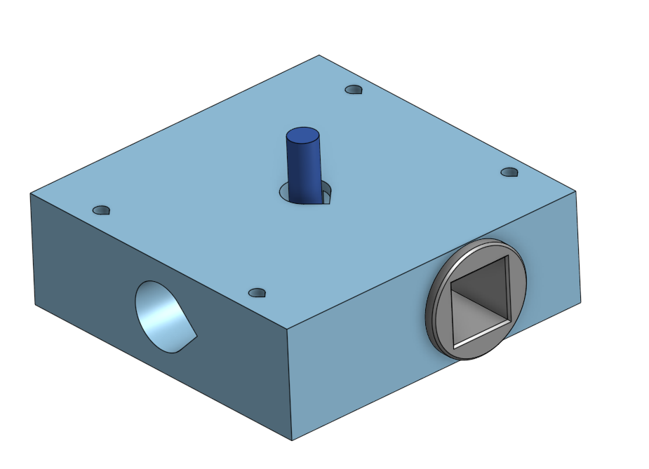
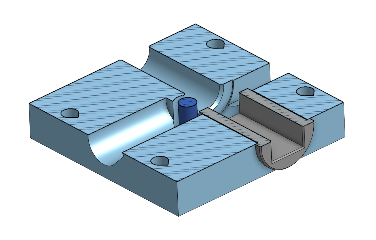
I’m still kinda hung up on the router/live tooling idea. This is where I got to a while back:
My thought was to print a block body with a dowel-sized hole going through the middle. Router mounts on top positioned so the tool ends up tangent to the final shape and a hole through for the tool. Counter-bored section for a rotating plug to support the square piece going through. Cross-hole bored for a shop-vac for chip extraction.
I think the router will need to be positioned quite accurately if I’m going to get it to cut on size so I probably need adjustability for position, even just +/- 1mm.
There’s no visibility into the jig so I’ve got no idea what’s going on… I could mount the router upside down and cut an inspection hole in the bottom, I guess.
Until the dowel is all the way through, I suspect it may chatter really badly.
So I’m really not sure whether to pursue that further or to try a more conventional lathe type approach.
Might add an additional guide bushing on the exit (for changing the dowel diameter) and an adjustable position for the router, so you can sneak up on the right diameter.
That should help with chatter until the start of the dowel fits into the exit guide bushing, at which point you can take heavier cuts.
Edit: might also move the dust extraction cutout to have more of an opening on the side the router throws it’s chips towards.
The adjustable bushing on the exit to change the diameter would be a great next step. For the moment I was keeping it a bit simpler by focusing on making one that’s a single size. Can always just print another one for another size!
Having a rotating bushing to support the square section on the output is an interesting idea that would allow for lighter passes which could in turn make it plausible to use with a palm router rather than my 3HP 1/2" behemoth. I had intended to be single pass but with relatively slow feed rate, but multiple shallow passes seems like a less ‘all in’ first step.
The router would be on top in this orientation. I’ve put it in this orientation so it would be conventionally milling and should be ejecting the chips towards the dust port in the ‘bottom left’ direction. The cutout in the ‘top right’ direction is to allow airflow in to keep the airspeed up, in theory.
That’s not what I was intending to go at, but a heavy cut is going to cause the workpiece itself to chatter more, no matter how big the router is.
So I was thinking to sneak up on the cut until it fits the (round) exit bushing and once you got the leading end of the dowel to the right diameter, hog out the rest with whatever bite the router can manage, wood is now properly supported on both ends.
Yeah, I think I follow you. I was meaning that there’s currently no way to support the outfeed unless it’s all the way to size, so having the same rotating bushing at both ends would work and allow shallower cuts, at least until the piece is round enough that it’s not well supported by the square bushing anymore, at which point it could just be swapped. I also thought a possibility would be to use either an existing correctly sized dowel or a 3D printed piece screwed/doweled into the end to ‘start’ it, if it ended up needing that.
I’m not sure of a good way to do the router position adjustment with it cutting on the side of the blade. I really wanted to use that so it was rotating the work into the side of the blade, but I wonder if it might be better to have the router positioned above the dowel and then I can use the plunge base and depth stop to set the tool position relative to the workpiece.
I definitely like the idea of being able to do this in shallow passes, at least at first.
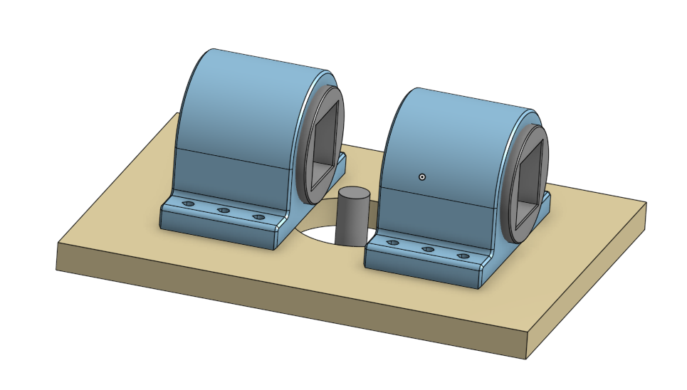
The whole body was proving to be a pretty big/expensive print so I might try to make one that’s in a couple of parts and just screws down to some scrap, for now. That would make it quicker and easier to iterate, at least.
Not sure if these ideas would scale to the length of dowel you require, but this guy is one of my favorite wood tubers and this vid has many ways of making dowels! At the very least it could give you inspiration:
I definitely could. I have a home-made router table and I could clamp it to the fence then shim it into place, I guess. With the goal of having it be sub 1mm accuracy on the final OD, just doing it by adjusting the fence might be a little bit tricky.
I’ve seen the ‘chisel clamped to a block of wood’ approach before but had forgotten about it. Using jigsaw or handsaw blades is a cool idea. It’s simultaneously obvious and yet something that I’d have never thought of or believed would turn out so well.
I think one of the key concepts that Matthias’ was trying to get across with his design is that curve in the blade, meaning it’s cutting on the tangent while also having a graceful curve in and out from the workpiece. Another approach to that could just as easily be a longer knife. I was thinking it’d be a great use for an old/damaged planer/thicknesser knife, something that had eaten a nail and had a big chunk out of it or something.
I like the simplicity of just whittling a taper to get it started, that’s definitely something I think I was over-complicating. I like the idea of just being able to stick a square section into it, but realistically clamping an angle grinder in a vice to use as an oversized pencil sharpener is absolutely my kind of jank!
That reminds me that I want to make a proper belt-sander jig so I can use it as a vertical stand with a table/fence.
Holy crap, I had to head out for the day and just got to the part where he’s using a circular saw. I’ve seen that same approach with a table saw but hadn’t thought about flipping it that way… That’s impressive…