DIY Digitizing Machine

All,

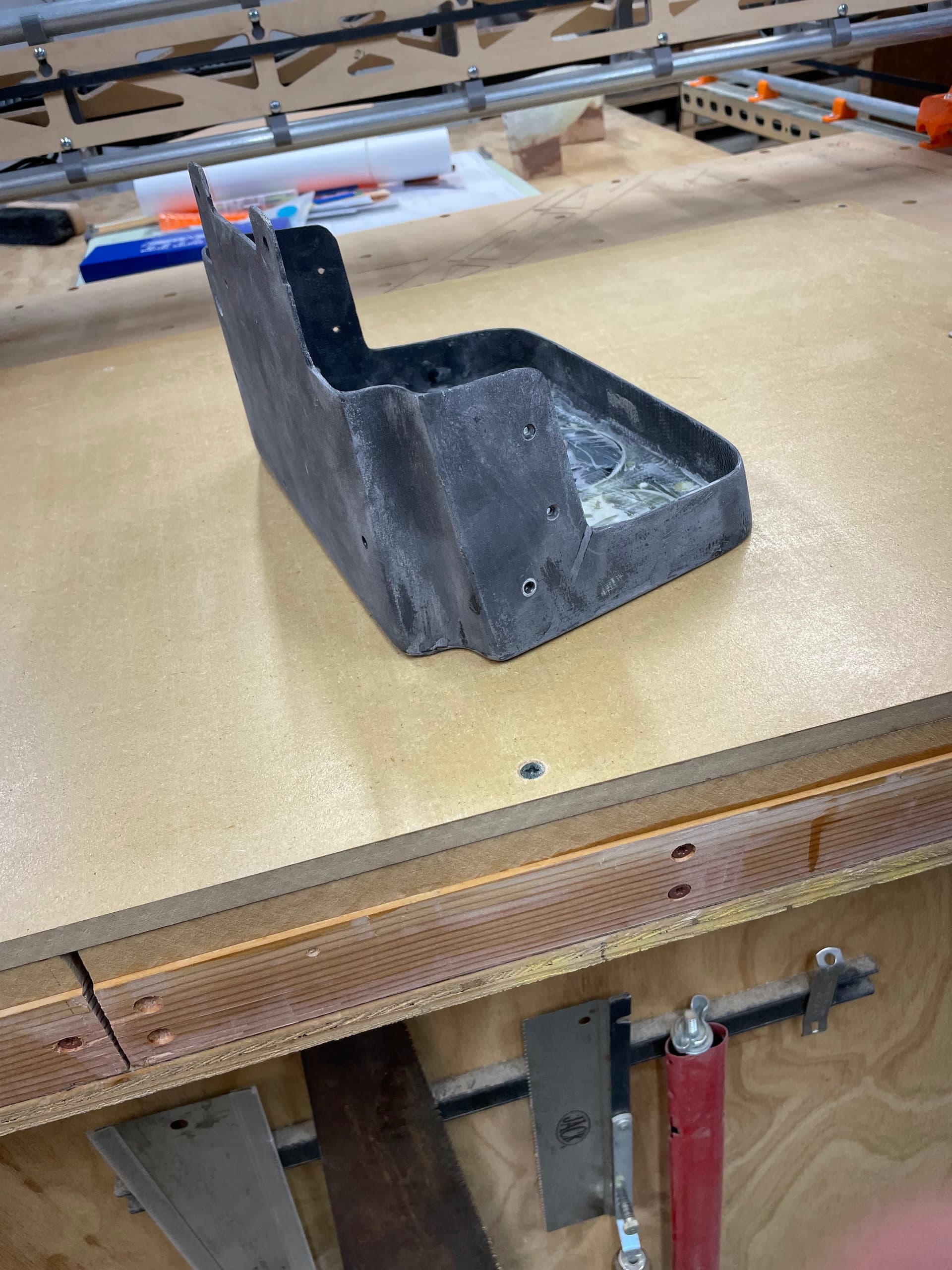
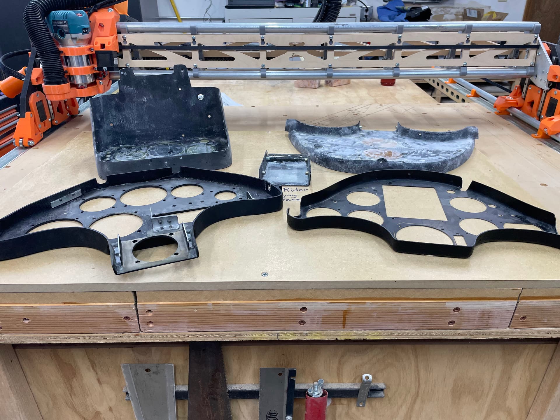
In my work with glider panels I often need to “trace” an existing panel. Particularly with regard to the outline of the panel. Many glider manufacturers have drawings, but they do not have dimensions.

I can usually find a set of horizontal and vertical reference lines to use while laying out the new instrument pattern, but they are not referenced off the actual shape of the panel. I often use the mounting holes as the points to determine my horizontal or vertical reference line and everything else is measured off of that.

So far that has worked and I haven’t had much of a problem with finished panels that are too tight for all the instruments to fit easily.

I’m now working on a rebuild where the newest part (a moving-map display) pushes all the other instruments away from the center and some of the edge-to-edge clearances are in the 1-2mm range. This is both the instruments relationship to each other as well as their relationship to the edges of the molded panel (where the sides are not perpendicular to the face!).

That’s a long explanation of the problem I want to solve, probably not for the current project, but for future projects where I need something to get a better measurement of the “true” panel size/shape.

Years ago I used a drafting table-size X,Y coordinate digitizer. It would be perfect for what I want to do.

So I was thinking that I could use the principles of a CoreXY machine to make one: replace the steppers with rotary encoders and count the steps instead of sending them. Make the legs adjustable to place the probe in specific heights above the “part” then move a vertical stylus capturing points with a push-button.

I need a maximum probe area of 24X24 inches. There are a lot more details to consider (what file format to use to collect the coordinates, minimum resolution, and many other elements that I sure I have no idea about, yet).

So, first of all, has anyone seem such a DIY project in their internet wanderings? Has anyone else considered that they might want something like this?

If there are several interested forum members that would like to collaborate on something like this, speak up! While I will be out of the country for most of the next month, I can touch base and keep up with the conversation.

Mike B.

3 Likes

I am not sure how to easily make it automated, but you can easily drive to a specific point and take notes of the coordinates. You can get as many points as you need that way.

1 Like

Some ‘tracing’ examples…

@marvinlange shared info on his overhead 4K Camera lightburn setup…

@jamiek implemented an Octoprint/MPCNC based DIY Digitizing Machine…

To ‘trace’ an existing part I’ve been taking pictures with a tape measure close as possible to the template. Then importing the image into Fusion 360, using the calibrate dimension feature, then sketching and 3D modeling from there…

Seen closed loop steppers/servos (with integrated encoders) used by robots/machines that can be ‘taught’ a task that they need to repeat. Keep hoping someone recommends configurably open/closed loop steppers on this forum (for recovering from skipped steps, this task, and others…) that don’t have mixed reviews, am still waiting/searching…

2 Likes

If you knew where the coordinates were, you wouldn’t need this machine.

I could see a stepper motor driven machine work. You would need something like a jog wheel to drive the machine under power to each feature and use your eyes or an instrument (like the camera) to determine when it was in the right place. Then you could save the current position to a file.

I think you could all of that with a gcode sending tft or arduino. Something similar to steve potter’s mega joystick and add an sdcard to save coordinates to a .csv.

This would definitely work. You need a microcontroller (like an esp32 or an arduino) to read the encoder via interrupts. A quadrature encoder is best, so you can sense blips in both directions. I would also install microswitches to get the 0,0. But if you are using the paper for reference, maybe it doesn’t matter. Reversing the kinematics to get the X,Y from the two encoders is not hard.

Then you need a button to know when to save a coord. It could spit out the coord to serial port, or a web interface (if you use an esp32) or save to a csv in a sdcard.

A big part of the mechanical design would be getting the pointer to have nearly zero load on it, and zero twist. The paper needs to be held firm and flat. Maybe it should be under a clear piece of plastic.

I almost think you want big knobs on the encoders so your hands aren’t twisting the machine. At that point, you might consider the open loop stepper motor control scheme.

This esp32/arduino project would have nothing to do with marlin or grbl. You need to never miss an encoder pulse, but otherwise, it is a pretty basic intro to electronics project.

2 Likes

I do this kind of thing fairly frequently. Usually it is for some laser project, but I’m currently doing this process on a drawing of a foam board RC plane (my first). My process is:

  • Get or make the drawing(s) into digital image(s). If it comes on paper, scan it in (photographs don’t work due to the distortion). If the drawings are in a PDF, get the individual pages as JPGs (online tools).
  • Assemble all the JPGs into a single image. I use an older version of Photoshop, though any image editor will do the job.
  • Use the assembled image as a background in a vector drawing program and draw the lines. I use Fusion 360 or Lightburn for my vector drawing. Inkscape and Illustrator will also do the job.
  • If the drawing is accurate, and with the distance known between any two points on the image, you can scale the entire vector drawing to accurately match the real size. If the two points are aligned horizontally or vertically, the vector scaling is easy. If they are not aligned, then a bit of simple math is involved. In Fusion 360, you can scale the drawing to match real-world sizes before creating the vector drawing.

As for a drawing machine, I second Jeff’s idea of using an Arduino ESP32 to drive a CNC. If you proceed with this project, I’d be glad to help some with the Arduino code. I’ve created my own pendant for my Primo, so I already have some of this logic figured out.

5 Likes

Just to be clear, I think Mike is looking for a solution like this:

2 Likes

I just took a quick look at these digitizing systems. A 24" x 36" version with 0.254 accuracy runs $2,400. That is not as much as I expected, but far beyond my hobbyist budget.

1 Like

@jeffeb3

Yes that video is closer to what I have used in the past: a wire grid under the table surface, and a "puck that moved around to input points.

I think I saw a video about tracing a shape and then using a “smart” camera on a CNC to find the lines and construct the shape. I also know that there are ways to take a digital picture and trace it with Inkscape to produce the DXF or other files format.

I’m concerned that that process will need several iterations to get close to the accuracy I’m looking to get: picture->Inkscape->pen plot on the LR3, repeat as necessary after measuring the plotted drawing, after scaling based on the measurement.

Also there is the parallax issue with the image. I worked with long room-sized cameras years ago and even then there parallax could be a problem. I imagine I can get a 30 foot telephoto shot that might be close. ( I was doing lithographic photography in the early days of semiconductor manufacturing. A BIG wafer with 3 inches in diameter.)

Thanks for all the suggestions, I’ll keep thinking about the process and maybe try the photography method.

Here’s a example of the most challenging panel I’ve done to date:

Note the inward sloping edges that I need to clear with the back portion of the instruments. In other words the face of the panel, where the instruments are seen, is larger than the available space directly behind the forward edge of the panel. Fortunately, on this panel I have plenty of room.

Mike

Also there is the parallax issue with the image.

I’m not sure of the nature of your artwork, but scanned images, and drawings rendered into PDF format (or any image format), do not suffer from parallax. I would not use photographs for a digital process.

I’m concerned that that process will need several iterations to get close to the accuracy I’m looking to get

Assuming your original drawings are not distorted, and are proportionally accurate, and you have an accurate measurement between two points in your drawing, the result will be spot on the first time.


I’m not trying to talk out of a mechanical system if that is what you want. And as said, I’m more than happy to provide some Arduino code that turns an MPCNC into a plotter. It sounds like a fun project.

@robertbu ,

The parallax issue would be with photographs, not drawings in PDF or other forms. As I noted above. The drawings show the front of the panel, but not necessarily the available space behind the panel. The drawings are not standard 3-views, but rather just demonstrate the manufacturers "standard layouts. Many of the panels I cut for pilot are using newer instruments that were never shown in the standard panels, so I often need to figure out if I can place instruments close together and still have clearances in the space behind the panel.

As I said above, the current project is keeping most of the standard instruments and then pushing them left,right, up, and down from their usual positions to fit a larger rectangle into the middle of the panel.

I am able to get that layout to work, barely! I didn’t design it. The client sent me a drawing which he calls “True Scale” but has no dimensions for the placement of the instruments. The panel outline appears to match the manufacturer’s drawings (which also have no dimensions, but are drawn on a 10mm grid). The instruments drawings themselves have very well drawn dimensions and hole callouts etc.

I better stop the rant about this drawing, but again my goal would be to be able to put the panel face down and then get the locations of potential interference by probing the back edges.

This has not been a common problem in the past, but I’m feeling like I may get more of these requests and it would be fantastic to have a tool that would help me solve the problem.

I have most of the electronics in my stash, and the printing of the CoreXY elements would be a good learning project for me.

But, Spring and Summer are coming and that is FLYING time.

I’ll put this aside for the moment, but thanks for all the input,

Mikeb

My dad had a huge CalComp digitizer, capable of a full blueprint sheet for AutoCAD work. Last I saw it it was on his porch in the rain, now long gone. Thx for the memories!

1 Like

I missed the fact that you also want Z. That is a tall order. Photogrammetry is getting better and better. I don’t know if it would be down to the mm.

Do you have a 3D printer? I have used a digital angle gauge (like this one) to measure some angles like that. You can try printing some quick test pieces to see how close you got and then iterate to a tight fit.

1 Like

Are the panels generally flat, or do they have curvature in them? Most of the newer solutions I’ve seen in this space have been optical/photographic rather than mechanical, since the optics in smart phones have been getting so much better so quickly.

I’m thinking of something like the toolKaisen app which allows you to lay a set of tools on a pice of paper, take a photo from 3 feet or so away, and will generate a tool tray inset automatically. These can then be plotted or cut in a variety of ways. I don’t know how this would work for curving workpieces.

1 Like

Oh, that’s neat!!!
https://www.toolkaiser.com

4 Likes

I didn’t know it either and testet it, I am blown away. How didn’t this make a shitload of money? It’s so simple to use.

1 Like

@ttraband

The front face is always flat, and the back surface of the mounting area is also flat and parallel to the front face. Everything else is whatever the manufacturer needed to do to fit and mount it into the glider.

Here is a picture of several panels, lying face down on the LR3.

The three in the back are for one two-place glider, and the other two are from different manufacturers.

At this point I think the idea of photogrametry is the best option. Back to more research, OpenScan with a Raspberry Pi looks like an option.

Mike

https://en.openscan.eu/scanner, Software - OpenScan ? Looks interesting.

2 Likes

Doesn’t the pilot need those!!

2 Likes

I am missing something here I think.
If the panels are always flat, it’s a very simple thing to trace in your cad software very accurately and very quickly without the need for any fancy stuff.

Of course you need to have a reasonably accurate photograph. An iphone has all the tools built in so I presume an Android would have similar.

At the risk of telling you how to suck eggs, but this might be helpful to someone else.

I do exactly this:

I place the object on an accurately gridded surface - this makes it a lot easier to check the scale after import into the CAD drawing.

1: The phone has a built-in level for scanning - simply align the cross hairs and you’ll get a very good result.
2: I’ve taken a deliberately out of whack shot for this demonstration - this will of course lead to some distortion at the end, but it’s mostly ‘good enough’
3. the “Crop” tool on the phone has perspective adjustment features - the symbols are pretty much self explanitary - vertical and horizontal and level. (this shot was level because - “habit” so l didn’t have to adjust it.
4: adjust the vertical perspective
5: adjust the horizontal perspective.

Now crop to a known dimension to make it easier to set up to scale in CAD, import it and trace away!
To get a sense of the angles of the flanges, extrude the traced drawing to the depth of the flanges and apply a “draft” to the extrusion to angle the sides and define the limits you need.

Sorry I have posted this here a couple times. This should be simple enough to work for you. https://www.instructables.com/Comparatron-an-Affordable-Digital-Optical-Comparat/

1 Like