I am working on the accuracy of my new Primo build. I tried drawing the largest rectangle that I could using a fine tip marker. I found that the lines were in different places on different runs. The first run was counter-clockwise and the second clockwise.
Any ideas what could cause this?
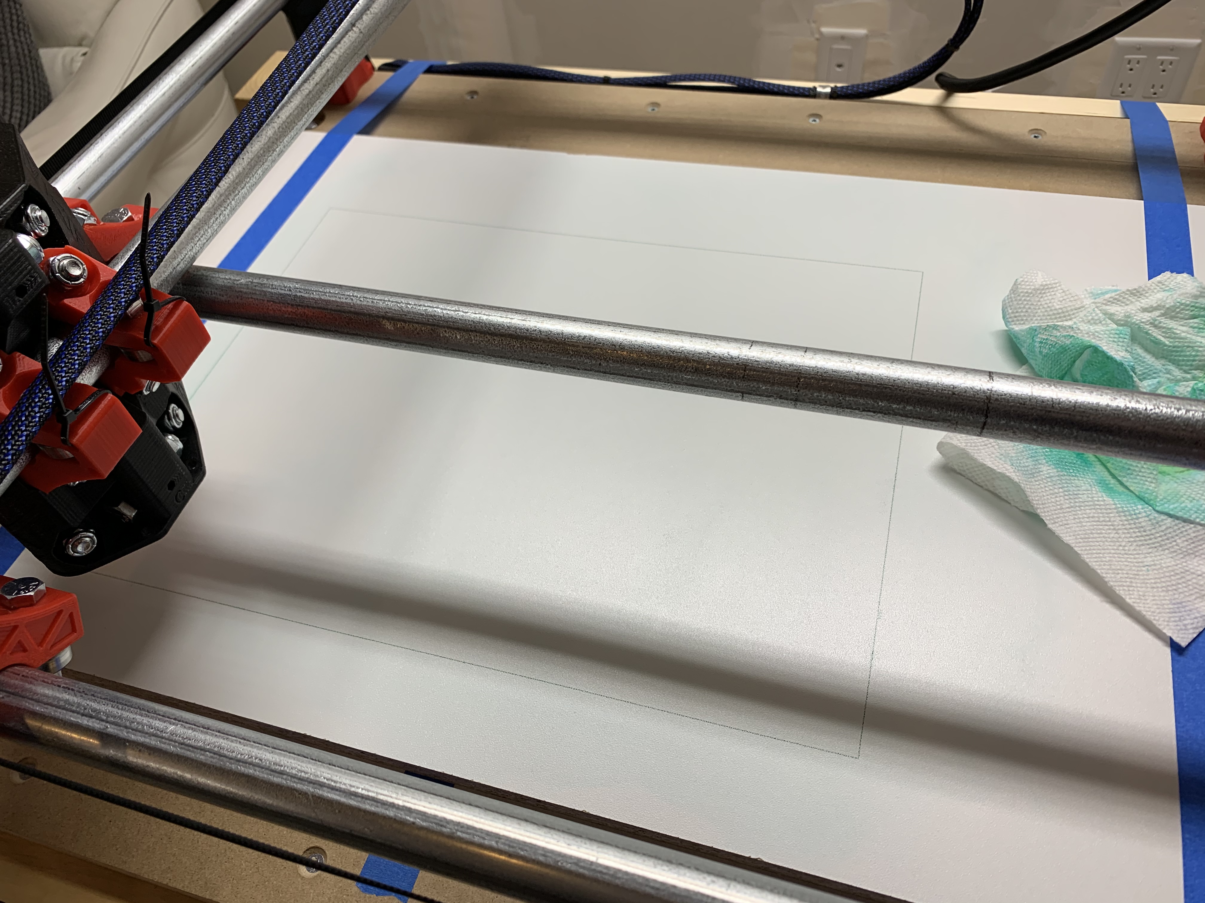
Here is a photo of the resulting rectangles. They should both be 400mm x 280mm.
3…2…1…Print! Heck yes. That first crown is so much fun. Thank you for sharing with us. Nice looking crown.
About your hysteresis, how far off are the lines? My first guess is the pen mount. If it was pushed down a bit too much, it can flex to the side instead of flexing purely in the Z direction.
The next guess is maybe a loose pulley. One of the grub screws needs to be right on the flat of the motor shaft and then tighten the other one. If they wiggle loose a little, they will rock back and forth on the flat and that will lead to a little lost distance when changing direction (back lash). Some blue locktite will hold them in place.
Ah yes, I think I did lower the pen 1mm more on the 2nd run. There was a missing line segment right at the end of the first run. Maybe the change is z shifted the pen a bit!
I will try again without changing z and see if it helps! Thanks for the tip!
Yes it was indeed the pen moving. I caught it in the act once or twice. The tip of the pen would get snagged a tiny bit on the masking tape that I was using to hold my sheets of paper together.
I had my son draw me a 400mm x 300mm rectangle in Solidworks so I could watch the CNC moving. Previously I was manually drawing the rectangles using the LCD GUI, so I wasn’t paying as much attention to how the pen was moving.
I also found that instead of using paper to draw on, it was much better to use a sheet of 1/2” melamine. It has the advantage of being really smooth and stable, but you can also easily erase old lines using rubbing alcohol. So it’s really handy when iterating during the end stop calibration. Just lift Z and wipe off the old pen marks before doing a another run.
One other question: I found my diagonals were equal, but 1mm shy of what they should have been. With X=400mm and Y=300mm the diagonals should have been exactly 500mm but they measured in close to 499mm. Is this something I can fix with GCode settings? I didn’t measure the length of each side, but I will tomorrow.