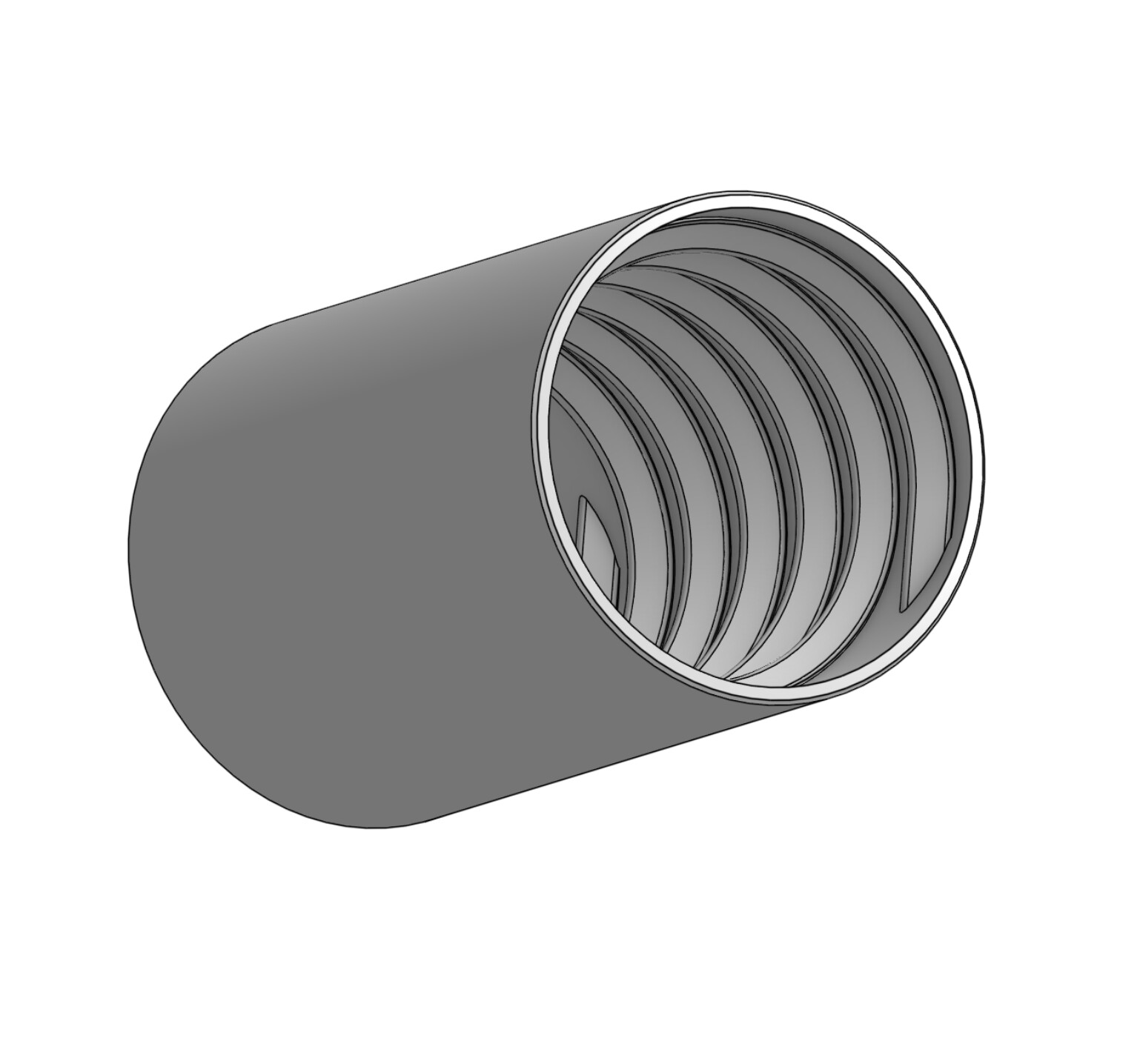
Here you go - it’s roughly 4" long - and I think it’s the correct size for your hose - it works for mine!
Print with a brim internally because there’s not a lot of surface area there! I’ve dropped the STL in a message - If you are happy to send me a photo when it works, I’ll upload it to printables for everyone to share. Thanks for being my test bunny!
For a very long time I’ve guessed wrongly, that your 2.5" hose was an OD and matched my 2" ID more or less - now I know that it’s not, it’s a simple thing to change, just need a couple of confirmation details, but it’s bed time for me so I’ll sort it in the morning!
For spiral intervals, I took this “stretched out” measurement (38.8 mm) from the start of one hoop to the start of another at 3 hops away. Does that help?
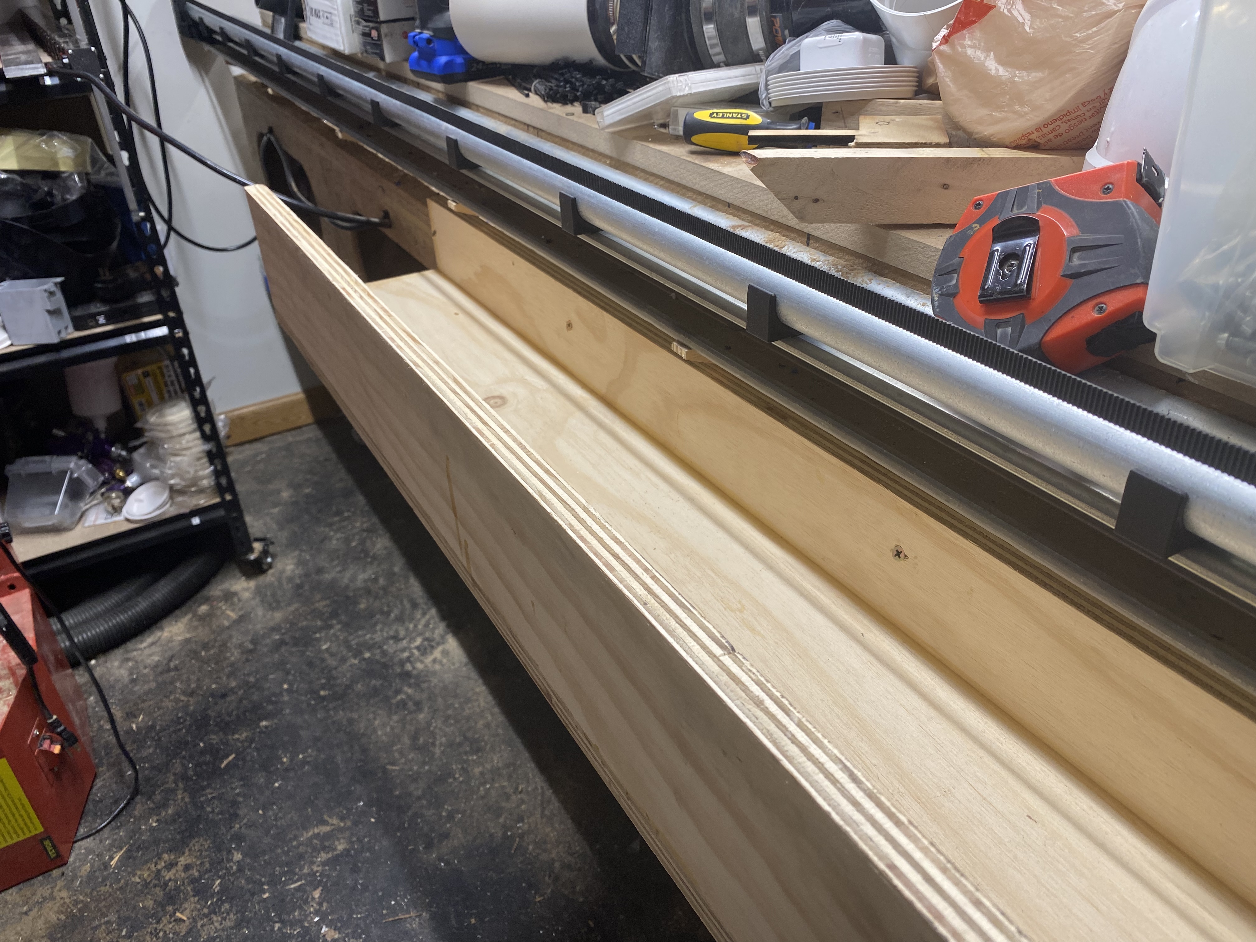
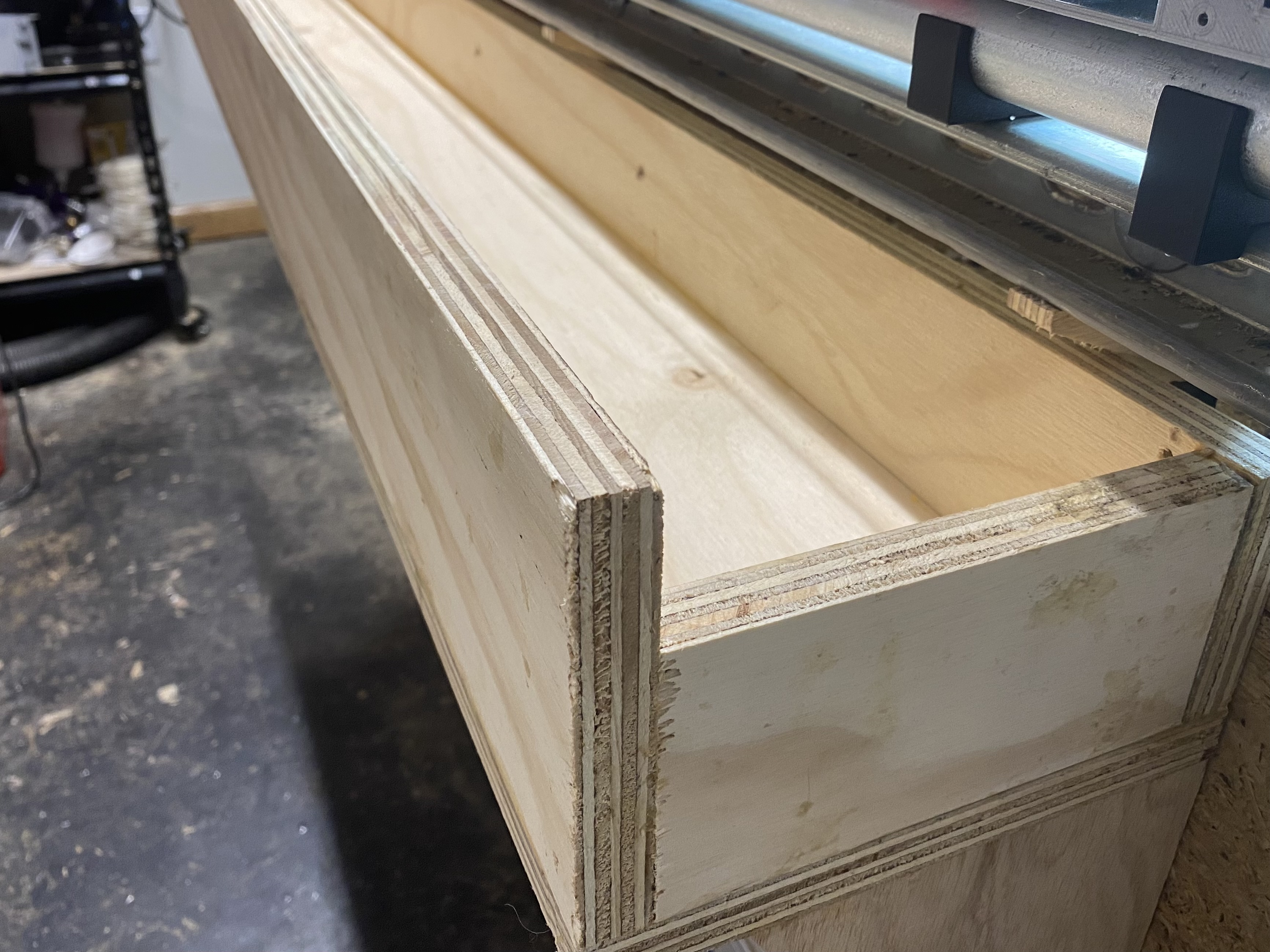
I had some scrap plywood laying around, so I used some of it to build a tray to attach to the side of the table to support the flex hose along the long Y length. Such a tray only needs to cover the half that is for the front half of the fully extended hose.[see note below] The glue is drying, and I’m turning my attention to how to get tool access permitted through the width of the tray to get it attached to the sides of my table. PS: the scrap was thick so the tray is so strong it is overkill. Way more strength than is needed to hold up some hose. But hey, it was free.
UPDATED November 18, 2024: Ok, this prior statement (“Such a tray only needs to cover the half that is for the front half of the fully extended hose.”) was sincere, but wrong. I was mistaken. At least if your flex hose is not stiff, it will sag down when stretched over the area where there is no tray. When that happened on my floppy flex hose, it sagged down, and then when attempting to return, it caught on the supported (fixed) portion of the hose at the start of the tray. So, I took the tray off, shortened the hose, and I am attempting to use it that way.
Turns out that tool access was no issue at all. Because the screws could be angled downward, through and on into the table’s sides, I was able to lift up the back of my drill (with a screwdriver bit in it), so that it was coming in over the outside lip. The hardest part was just holding the tray in a somewhat level position with one hand, while trying to get the first screw in it, using the other hand.
Thanks! I’ve sent you the new version - it’s tricky without testing.
I’ve made it exactly 69mm ID which means that it will be very tight - as you screw in, the hose will want to expand, so the trick is to kind of screw the spring to compress it in the opposite direction to turning! The idea is that the spring in the hose will pretty much lock it in place during use.
I am guilty of using a little talc on the threads to lubricate them on occasion, but I’ve never had any come undone!
It should work - but please just print a slice to check!
The tray will work really well. It looks a little shallow to my eye, just be sure it constrains both thicknesses of hose - but it’s no big deal to modify.
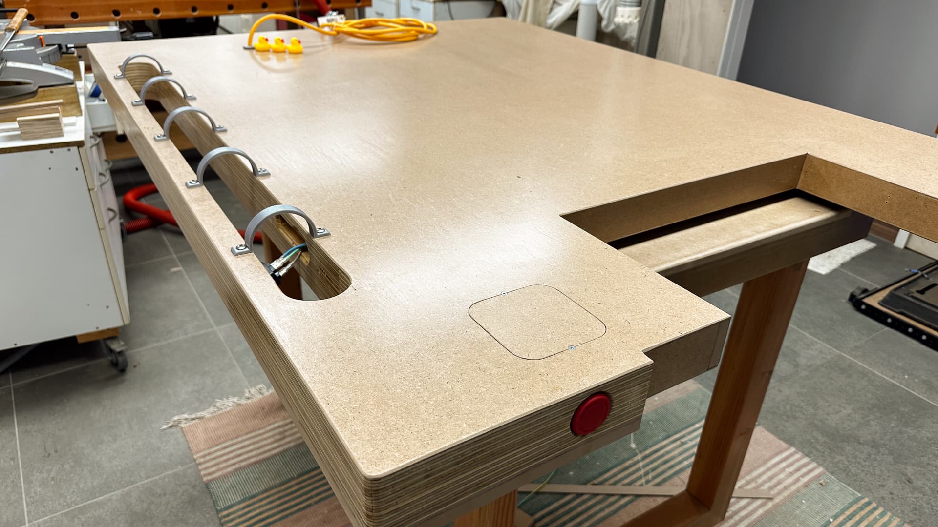
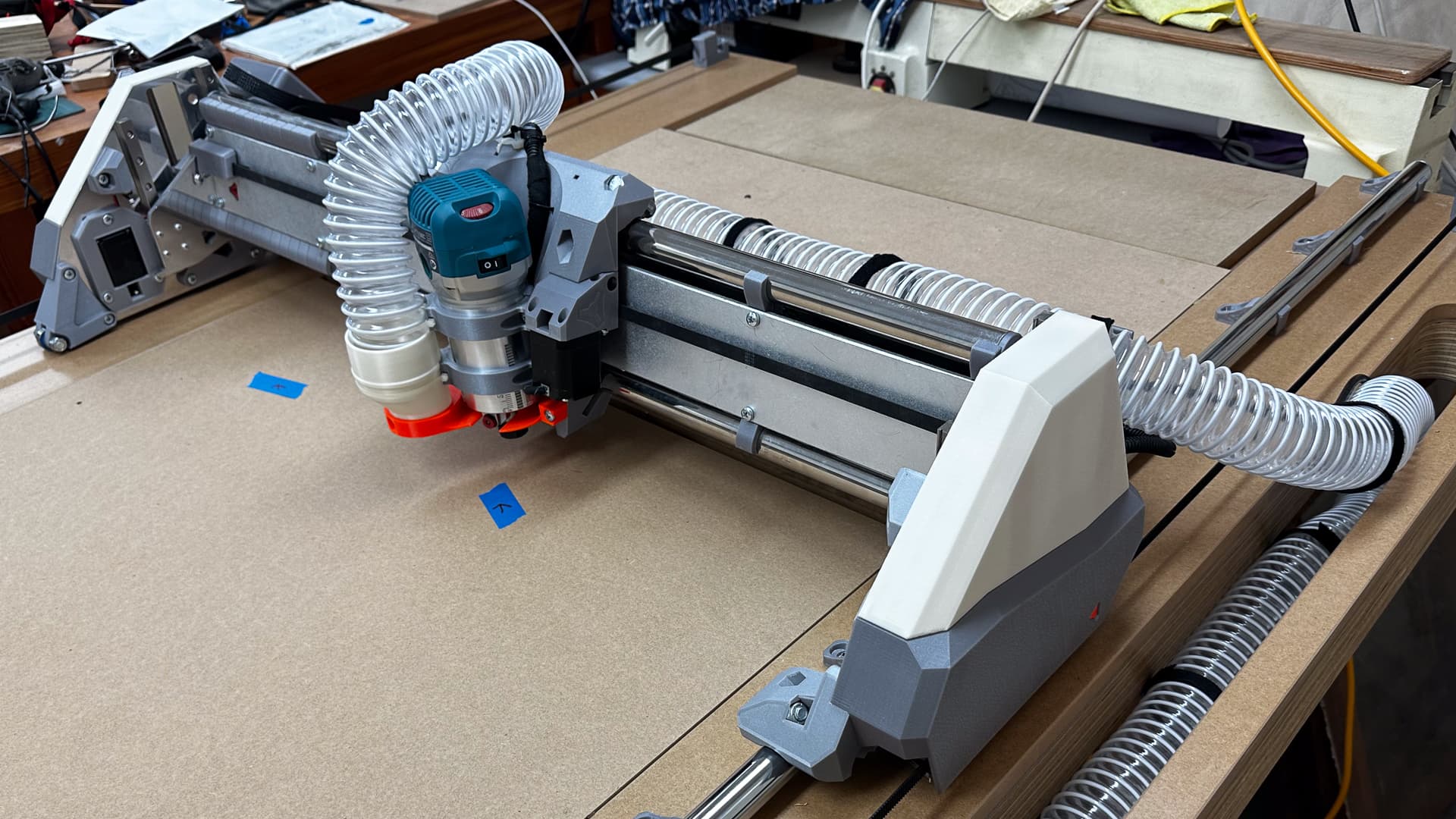
Here’s my version for reference, with printed “hoops” (table is upside down) so I could make it deeper if necessary, but it works well as is.
OK, good news is, it worked. Here are some additional details.
I had to change filament about 80% of the way through. Not only that, but I had to change brands. The earlier portion printed with a slightly matte finish. The latter portion printed with a slightly more gloss finish. You can already see where this is headed. The matte finish provided less friction, and it was more doable to get the tight fit “screw in” accomplished. On the glossier section there was more friction, and it was much harder. All in all, assuming folks know about the talc trick, I think your dimensions on this are spot on.
Out of pure curiosity, why did you move away from the printed brackets?
I’m reluctant to build a trough that will collect debris and dust. I can vacuum it, but I’m thinking I’d rather have the open bottom so the excess could fall through for the broom.
The hose is pretty floppy. Was it just a matter of the necessary support?
I initially was thinking about it as either a tray or printed brackets, and in that context, the thought of printed brackets felt like some thing I would continually be bumping and scratching myself on, and possibly breaking off. It wasn’t until later when @bitingmidge PeterH posted a photo of his that I realized I could have made a box with no bottom and put printed braces on the bottom of that and kind of had the best of both worlds. I may still retrofit that approach into it.
That makes sense. I was thinking the trough with an open bottom and bracing supports for the hose. I didn’t do anything on my LR3 and I did have snagging problems.
Eventually I will get my setup/build completed and likely turn my attention to making a parametric version of those back covers that can accommodate the various different intervals between braces.
My work to revamp dust collection continues. I’m currently prepping to use LR4 (RC3) (smaller table) to cut OSB to make a lid for a “2nd stage” use of a trashcan to hold a Super Dust Deputy 4/5 on top of it.
My full size LowRider table has my smaller LowRider table sitting on top of it, along with several projects worth of clutter. Since my smaller LR4 (RC3) is j-u-u-s-t big enough to cut that lid, and it’s the CNC that’s on top and not buried, I’m prepping to use it. Project will involve three operations, holes, pocket, and profile cut.