hey im sure this been asked b4 if so can u point me to the topic
lot of the things ill be doing is on slabs , some of slabs wont be surfaced left in natural state , so hard to set start Z height
so im thinking leave home bottom left
always take height from X0 Y0 at spoil board level and do negative cut depth
eg -45.mm
main question is there a code I can add in here to take X, Y to a start point from home before it starts cutting code
say X600 , Y1500 if i want start in centre
that way i can move area of slab to that start point
yeah ive tried the whole manual jog which is fine if slab is surfaced
my table is 3 meters x 1.3 meters
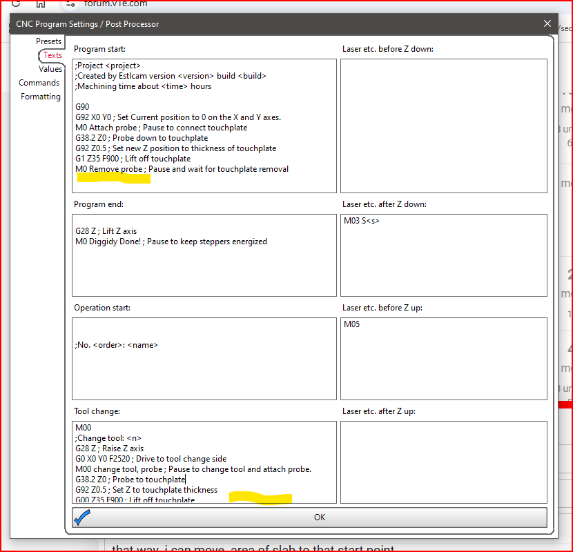
im picking id add line in here highlighted
unsure of which G code to put
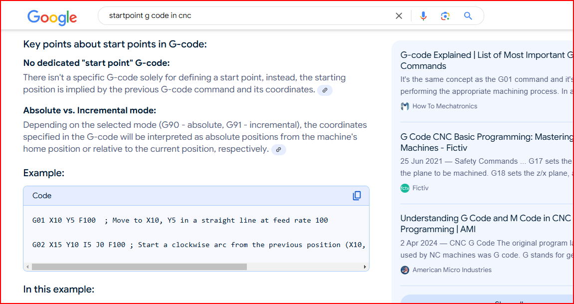
from the example i found
would i put G1 X600 Y1500 F3000
or is it a G91
am i on right train of thought , or just derailed
if ur wondering what the
G1 Z35 F900 is
i find it quicker and easier to remove dust shroud to change tool bits and probe
Z 35 is high enough to slip shroud back on after probe down
my table is 900mm off ground so need kneel down to change bits
easier to slide big slabs on to table than lifting on to higher one
You do all this in the CAM software, you should not manually need to do a move to the middle. If your program starts the cut in the middle it will get there itself.
As for the Z stuff I am unclear to what you are asking for.
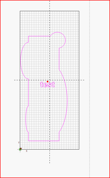
if my x0 and y 0 is where the green dot is and i probe there and do tool changes there. i want to than move router to red dot than pause , so i can move my work piece center to center or router bit than start cuts
You can move wherever you want. All the CAD outputs I see on this form use absolute coordinates (G90), so your command of G1 X600 Y1500 will work just fine. Your feedrates of F3000 for X,Y and 900 for Z are faster than I would run on my Primo, but the max federate in the firmware may be limiting the real feedrate. I’d hate for you to lose steps by running too fast a feedrate.
If you want to do this move for every job, you can add it to the Start Code section of your CAD program, or the Start Code section of your g-code sending solution (assuming you are not running off a SD card). You could add a pause (M0) to that code then have it return to 0,0 when you are done. Some g-code sending apps allow you to attach g-code to buttons, so you could add this to a button and execute it after homing but before the job is run.
If you want a low-tech solution, you could hang a weight on a string at that coordinate with a clip for storage. Pull down the weight, center the board, put the weight away. No messing with g-code.
P.S. Lightburn (for laser work) does use relative coordinates, so this solution would not work using Lightburn, unless it was done before the job is run and has a G90 in the code. But I don’t think you are doing any laser work.
cheers for understand my Question
no not for laser
i just do lot of my text etc and resizing of logos , in lightburn as quick and easy than export as dxf ,
than open in cam software
im assuming ur thinking F is in mm/s its mm/m
yes wanting to add command into program code
its just more practical for me that every job starts in center of table
due to odd ball shaped /size things im working with
will add to my settings and do some air runs and see it it works
and probe/tool change at spoil board height X0 Y0
My personal experience has been that Lightburn DXF files imported into Fusion 360 don’t come in at the correct size. This is true no matter what import settings I use. It is probably user error, but it is a simple fix to resize in Fusion 360. I often include a reference rectangle in the DXF, making the rescale calc easy.
On the other hand, DXF files exported from Fusion 360 and brought into Lightburn do come in at the correct size.
thanks dave
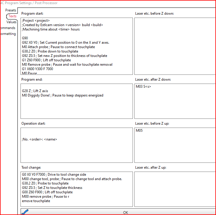
couple things is the G92 x0 y0 below so it rehomes before starting so after tool change it has the same 00 incase u bump spindle while setting material to midpoint
is it nesscury to have G0 X-600 Y-1500 F3000 in tool change, as once material screwed down dosent move till job finish
my current setting used for couple jobs and it works as i think it should
All G92 does is change the current workspace coordinates to the specified coordinates, G92 X0 Y0 makes the current location the origin/start/zero point. All Estlcam G-code X,Y coordinates that follow will be (and Texts entries need to be) some absolute (G90) distance from that X0,Y0 point. If the origin is X600 Y1500 from machine zero and you want the tool change to happen at machine zero you need a G0(0) (rapid move, not G1 machining) X-600 Y-1500 to get there.
My answer was for projects that have a center origin point (blue +, Zero tool), a setup that works with any size material/project that fits on your machine… Two centering options were posted in a previous reply (Centering Workspace Estl CAM - #5 by dalrun), here’s a third (the 4th/bottom Select icon can be used in newer versions):