I’m trying to cut a double sided version of the classic Aggravation marble game. Because the size is bigger than my Primo it needs to be tiled. I worked out all the alignment in Inkscape. There are 2 tiles for each side split on the Y axis so that when I flip the workpiece things will align.
I cut the two tiles on the first side with no issues. Everything aligned perfectly. I flipped the board and cut the first tile on the second side and things looked fine. I know this because all 4 tiles have the outer edge set to cut just over half the thickness of the work piece with holding tabs. These “slots” aligned all the way through the work piece. There was maybe .1 mm off but easily fixed with some minor sanding.
So on to the 4th tile – where the aggravation sets in…
I first cut the outer edge, and things are off by maybe a mm shifted in a +X direction. Again not a huge problem but concerning. The second cut is what I call a marble track – a semi circle cut with a ¾" cove bit. It’s cut 5mm deep at 1mm intervals. After the first pass I see that the cut is shifted about 3mm in the +X direction. The drawing below shows (not at scale) what I’m seeing.
BTW I checked the gcode directly - the integer X values in both tile1 (bottom) and tile 2 are the same all the way through the first cut of the track. The decimal values are slightly different. So I’m more confused now…
I’ve not done enough double-sided milling to have an answer to your question, but as I try and think the problem out in my head, I’m missing information:
Where is/are the other peg(s)?
How are you flipping it in relation to the pegs (vertically or horizontally)?
How do you move the stock to do the second half of each side (slide or rotate)?
Where is the origin/home of the job in relation to the pegs and the stock?
Do the stepper remain engaged during the job, or do you re-home the machine and move to the job origin?
Any chance you are losing steps? Does the router bit return to the correct job origin if moved to (0,0) at the end of the job?
origin of the drawing in to the surface of the waste board
Y center of the drawing just through the work piece (both have the same X value)
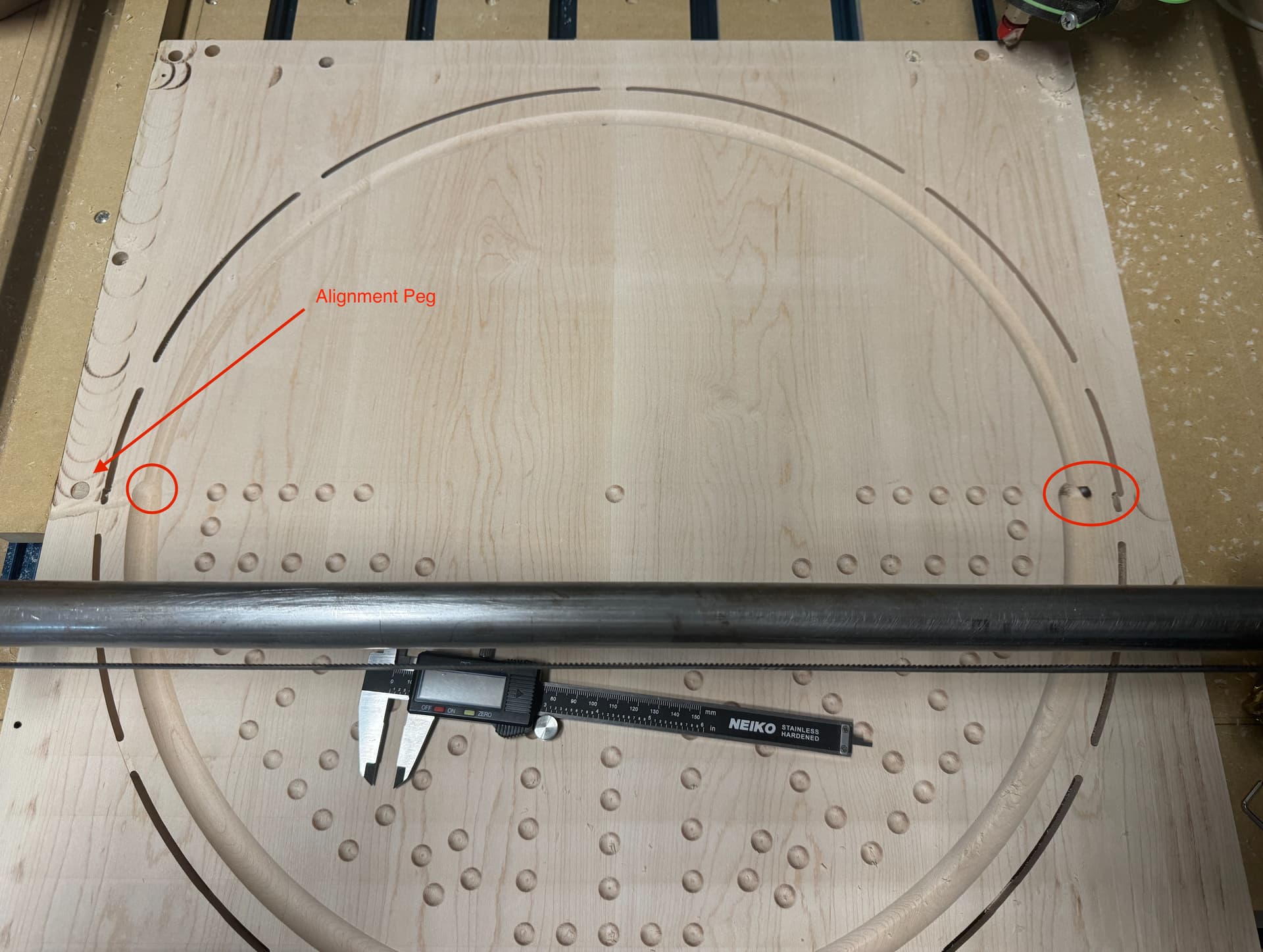
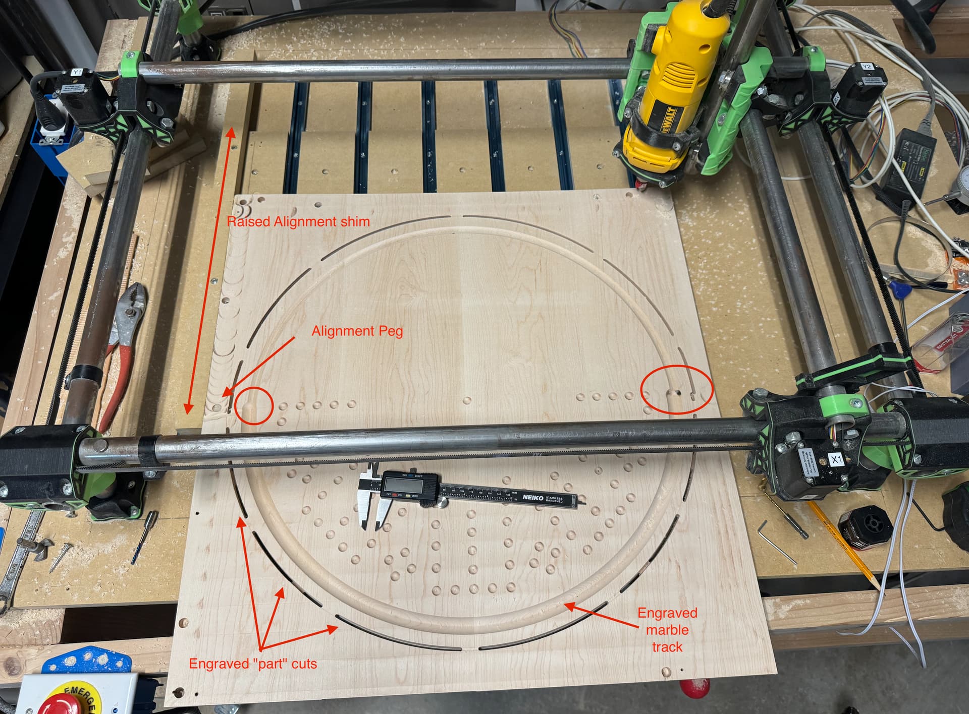
I setup a shim on the left to assure alignment on the X axis (hard to see in the picture)
To cut the second tile I slide the whole workpiece down and put a peg in the workpiece center peg hole and the origin waste board hole. This is shown in the picture.
To cut front and back I flip on the Y axis using the center workpiece peg hole and center wasteboard hole.
I generally leave the steppers enabled between jobs, change tools, home Z, and start the next job. After cancelling this job I powered cycled everything. I then reset the origin coordinates and started the job again and cancelled at the same point. The end location was the same as the first time I ran it.
As far as I can tell I’m not losing any steps.
Using Inkscape / Estlcam for the design/cam software
By origin of the job, I meant in relation to the top of the stock. Are you using the center of a peg, or the center between two pegs, or something else as the X,Y position?
I still don’t have the full process you are using straight in my head, but your use of a shim makes me suspicious that this is a rotation issue, not a shift issue. Somehow your process is not assuring the stock is squared the same as you make your flips and slides. This might happen if the sides of the stock are not parallel and you are using a different side for your shim.
I’ll describe how I would set up the job. Since I’ve never done a two-sided, tiled job, this is theory, but it might give you something to think about. For this description consider the X axis passes left to right, and the Y axis goes bottom to top.
I would place the pins on the left and right edge of the stock centered top to bottom of the stock. The job XY origin would be the center of the stock, halfway between the two pins. I would flip the stock across the axis created by the two pins (around the job X axis). I would move from milling the top half to the bottom half of a side by spinning the job around the job Z axis (i.e. rotate like a record using the job origin Z as the pivot). In Fusion 360, I know I can define the toolpaths for the top and bottom halves using the rotation around the Z axis. I don’t know if this can be defined in Estlcam ( I’m not an Estlcam user). This process only depends on the pins, and never uses the edge of the stock as a reference.
If you must do a slide to reach the two halves, I’d consider four holes, so the two pins just slide to two new holes.
I have a Primo with a cut capacity of 600X and 450Y. The waste board is raised ¾" MDF in 3" strips slightly smaller than the cut area. These strips are separated by T-track for hold downs. This way when the waste board is surfaced it doesn’t create a “hole” in the surface. This is really only important when trying to cut things in tiles as these work pieces need to stick over the edge. A “hole” in the wasted board would make them unlevel. All of this is closely aligned with the machine origin in both the X and Y directions.
In the process of redoing my washboard in preparation for this project I neglected to put a partial piece of MDF at the farthest right side (X max) so I now have no way to create a second alignment hole. It’s a problem I know – but here is what I did to lessen the need for it.
I put the side one of the work piece down and moved Z to 1mm over the workpiece origin. I then ran the spindle out to Y450 and aligned the top of the workpiece and then ran back to Y0 and checked the alignment. I then screwed down an alignment shim down to the waste board so that I would ensure that is was fixed.
I have 4 tiles to cut
side 1 bottom
side 1 top
side 2 bottom
side 2 top
Each tile I run the following jobs on a 20mm thick work piece
surfacing the work piece ( .5mm deep )
alignment pegs - 2 holes along the left side of the workpiece (really only necessary on bottom tiles) (30mm deep)
engraving the outside “part” cuts half way through the workpiece with holding tabs (11mm deep with full depth tabs)
engraving the marble “track” (5mm deep)
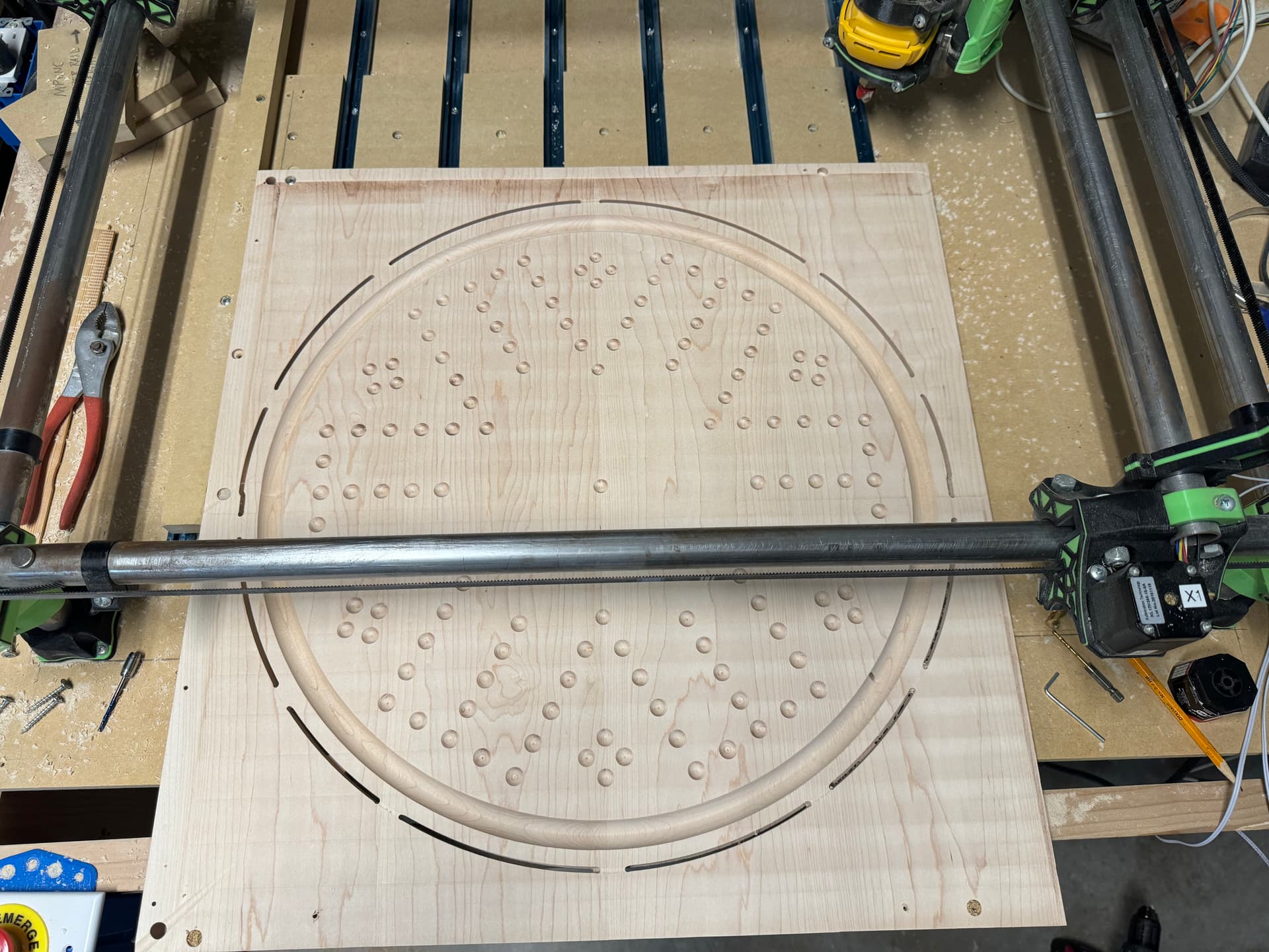
drilling the marble holes (3.5 mm deep)
Between the side 1 and 2 I flip the piece vertically (around the X axis) using the alignment peg to ensure the center and the alignment shim to ensure the piece isn’t significantly rotated.
This all seemed to work fine for side one of the project. There was a tiny bit of error in the “part” cut but not so big that it couldn’t be fixed with a sander.
I flipped the piece and started on side 2. I ran the jobs for the bottom tile and was able to see through the “part” cuts so I know the alignment was quite good. I then started on side 2 top and this is where I ran into the issue in the initial post.
I will say that Estlcam has NO knowledge of tiling operations. I dealt with this by chopping up the drawings in Inkscape and doing each one in Estlcam. This it the reason that I had to use engraving for the outside “part” cuts as Estlcam will only allow actual Part cuts on a closed shape. So I faked it with an engraving cut that luckily supports hold down tabs.
I have attached all the Inkscape drawings for anyone that’s interested. Forum won’t let me upload Estlcam files.
6 player (side one) - tile 1 is bottom / tile 2 is top
I never really figured it out. I did finish the piece though. I reran the last estlcam job and then used a sander around the edges and a lot of hand sanding of the marble track to “force” the alignment. You can tell if you look close enough but It looks/works well enough.
If I am looking correctly I think you may have hit the limit of your machine, meaning Core hit the truck. Then you lost steps and it finished. Just a theory. (may not matter now.)
It’s possible that there was a collision that I didn’t see or the core got “twisted” somehow. It’s also possible that my feeds/speeds were too high and causing some deflection.
What you can’t see from the picture is that the other side was carved correctly (in 2 jobs). One side is a 6 player version and the other is an 8 player version. The non visible side was perfectly aligned between the 2 jobs. My assumption is that I some how messed up the initial inkscape drawing… but without trying again