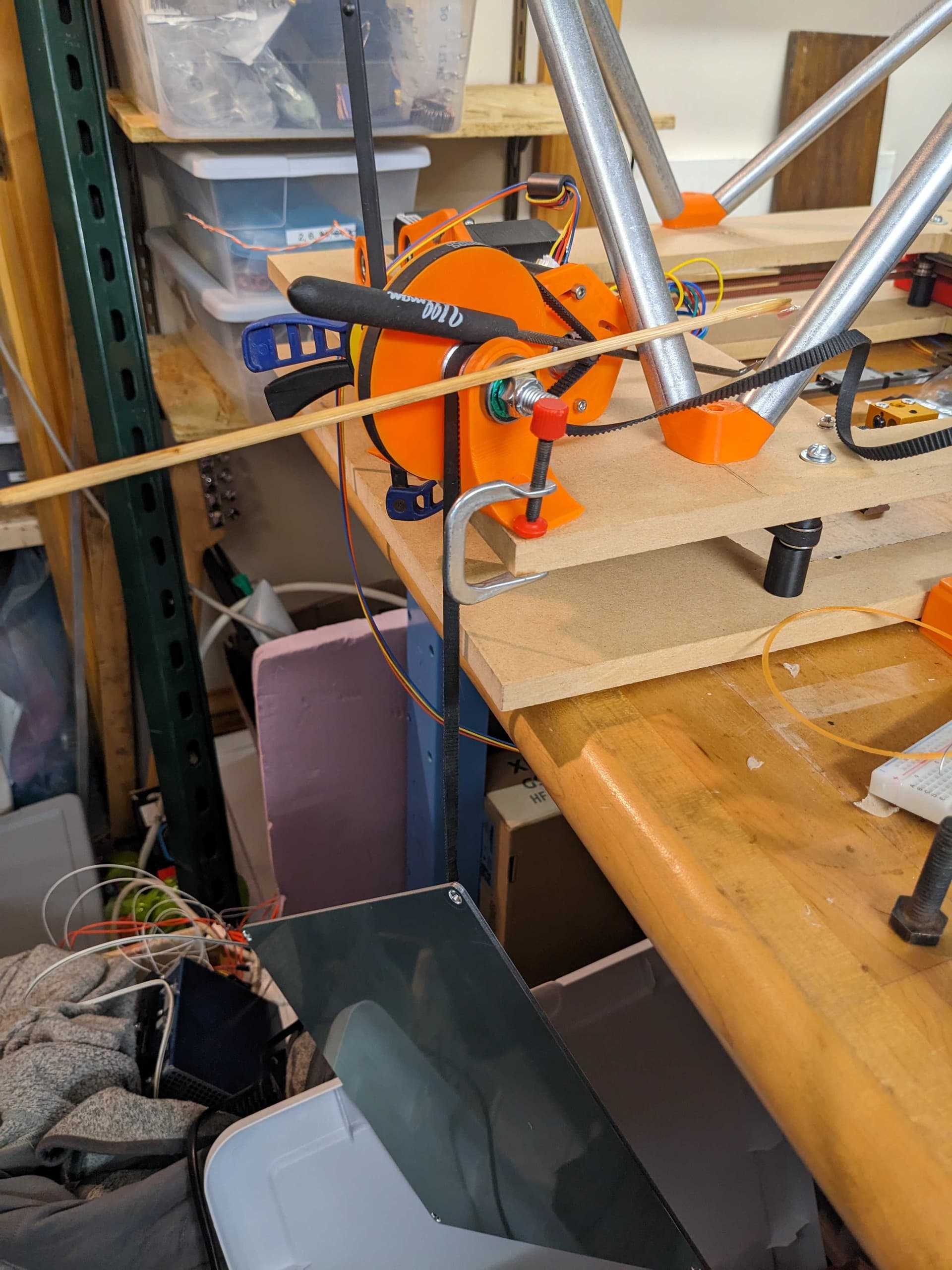
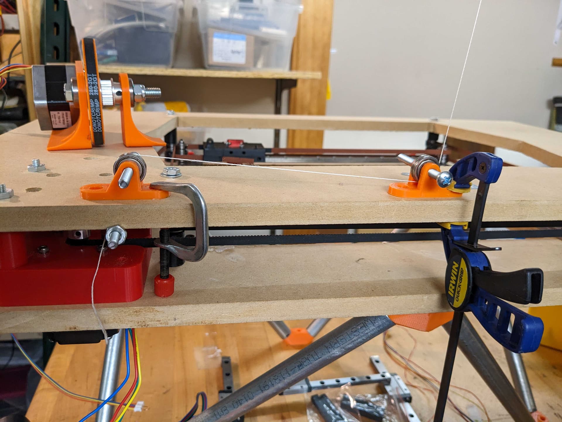
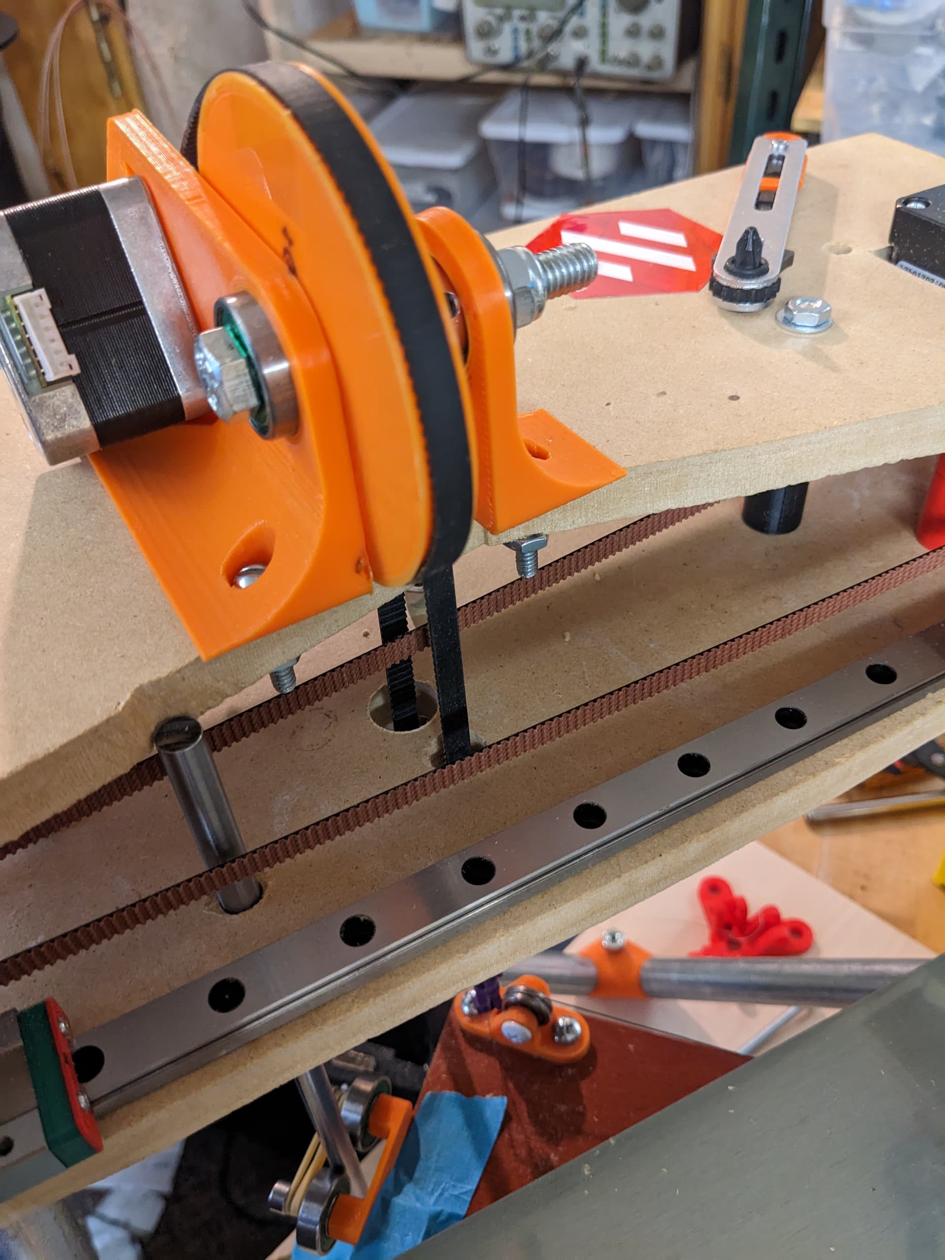
Added some shims to the flanged washer stacks so the belt had a littlemore room to run, adjusted the drive pulley locations, tightened belts, and still had the same resonance problem.
I tinkered with a few more things then discovered that my motor drivers were configured to use stealthchop instead of spreadcycle. Fixing that allows me to run at any speed I tried between 50-1000mm/s
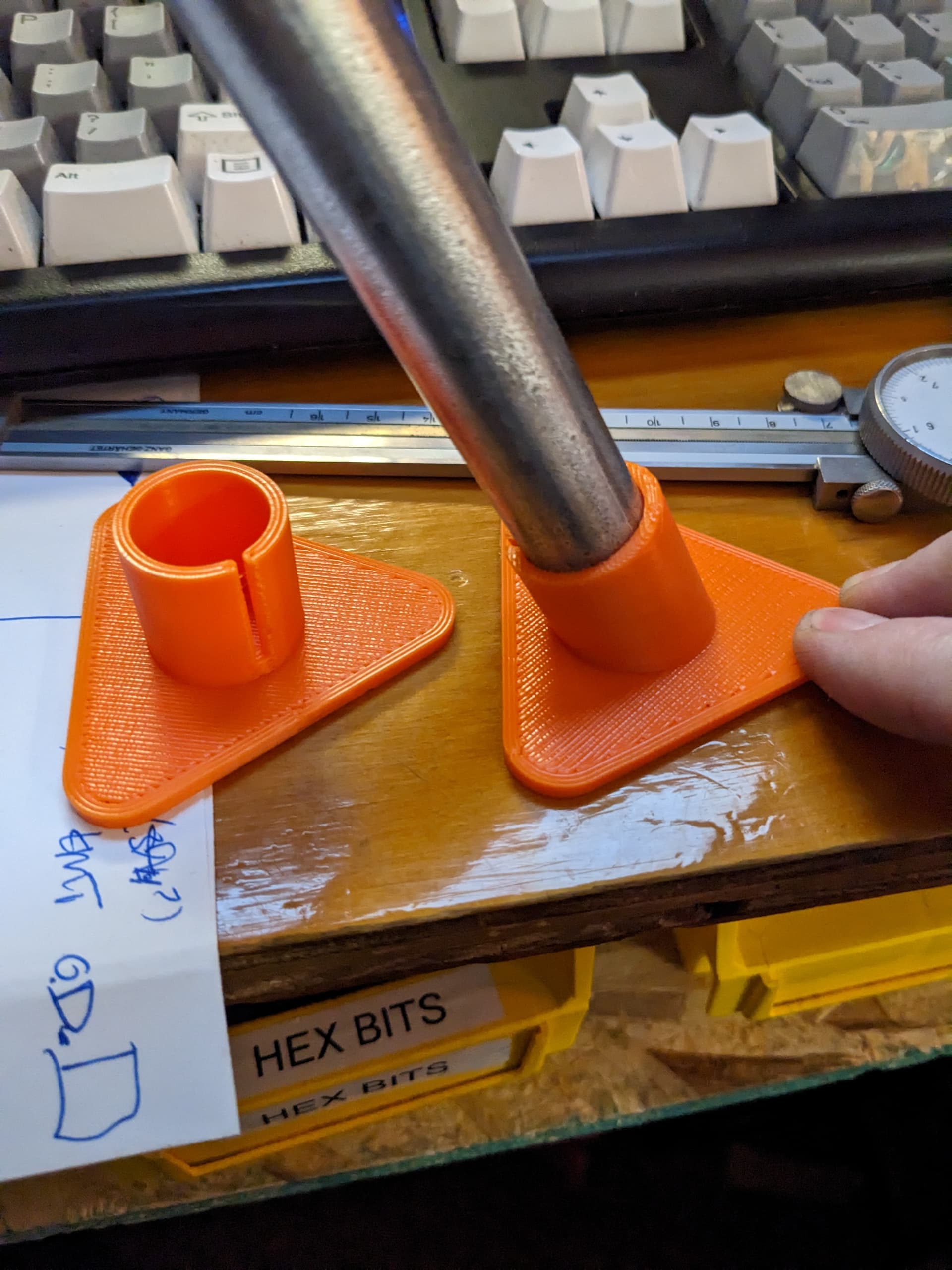
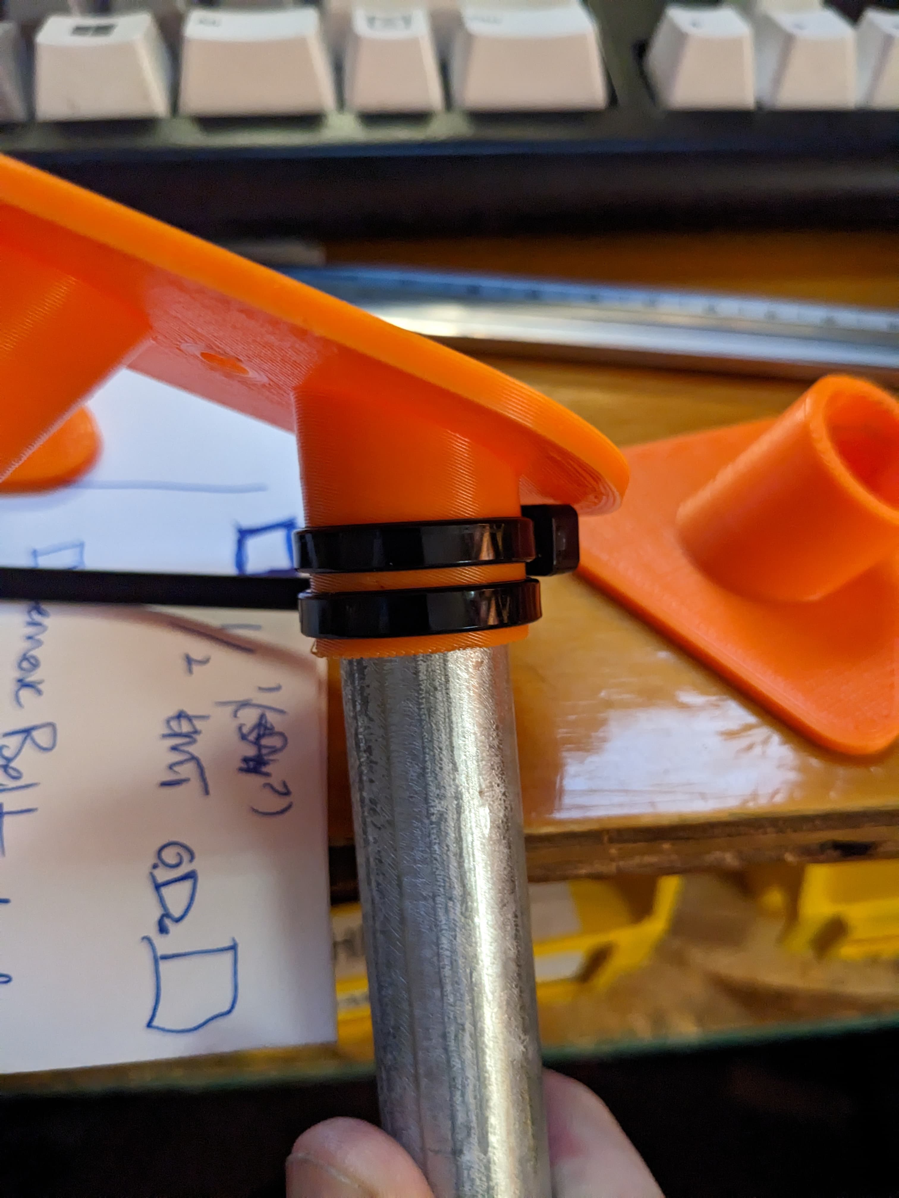
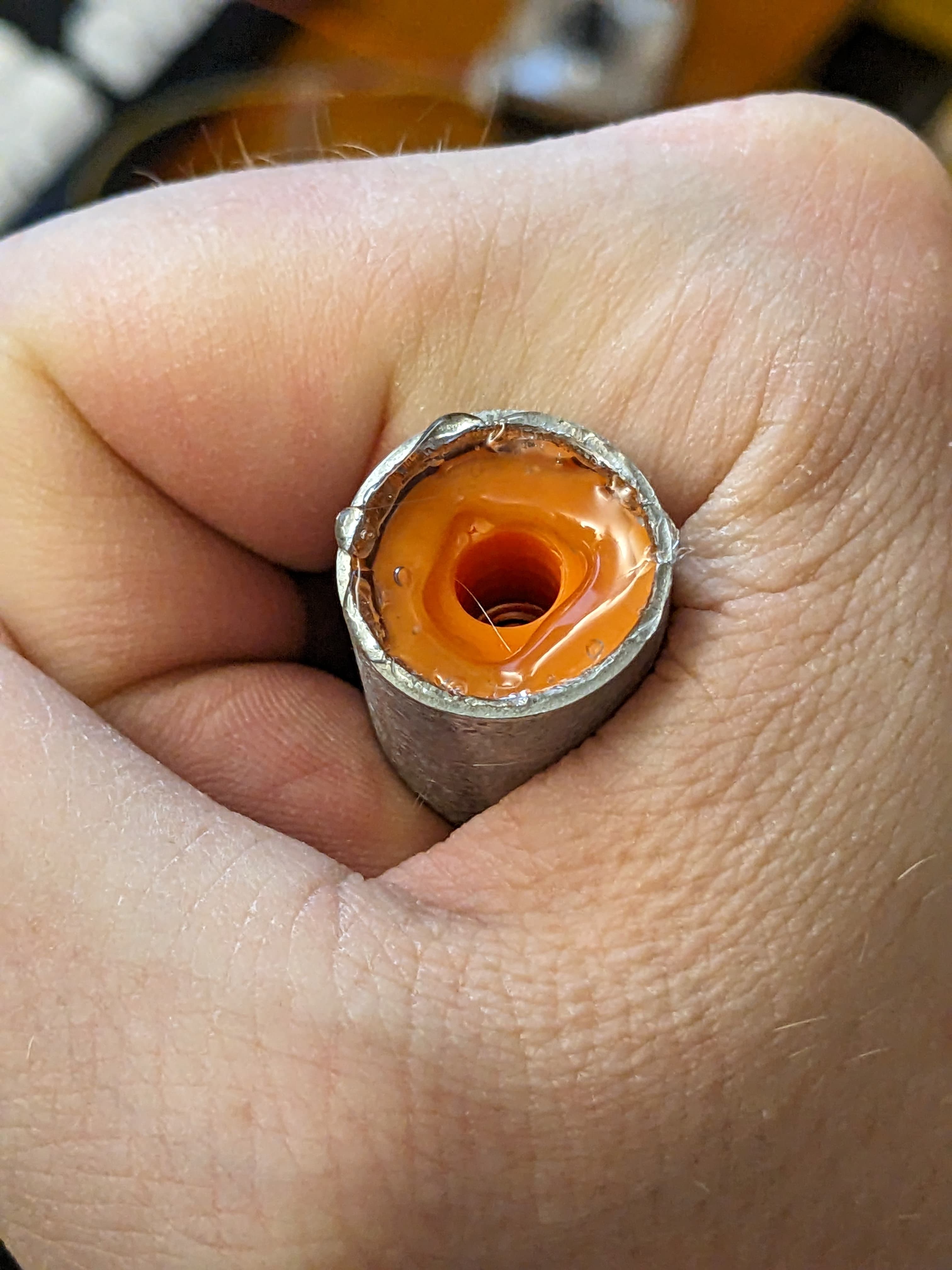
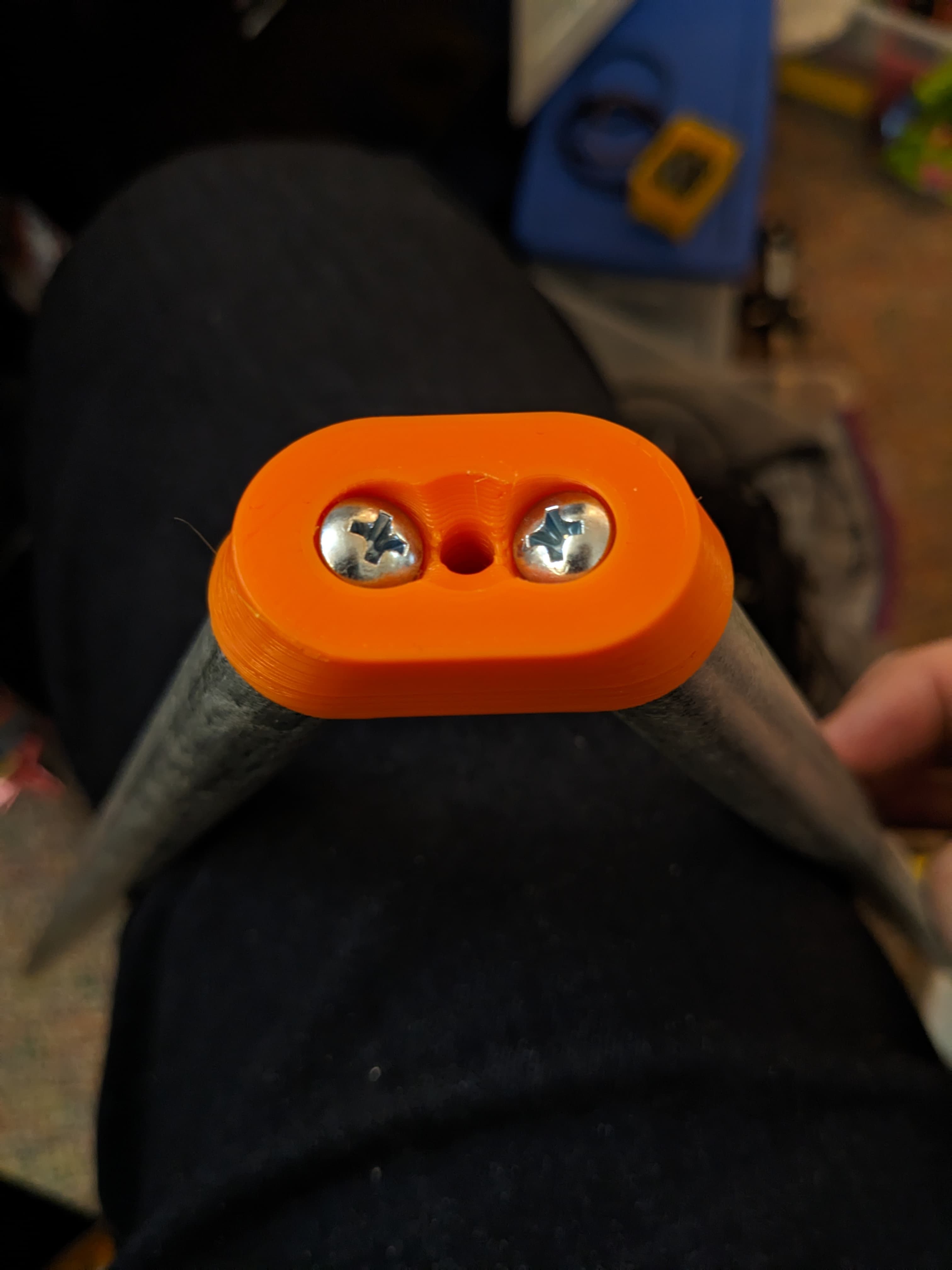
Further iterating on the connectors. I’m keeping the clamping feet for the lower end of the legs but going in a different direction for 2x and 3x connectors. I’m epoxying a plug with captive nut inside the pipe and then screwing them on to the connector.
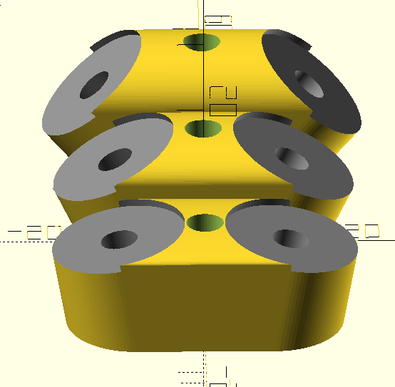
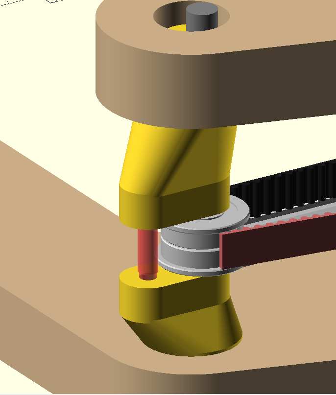
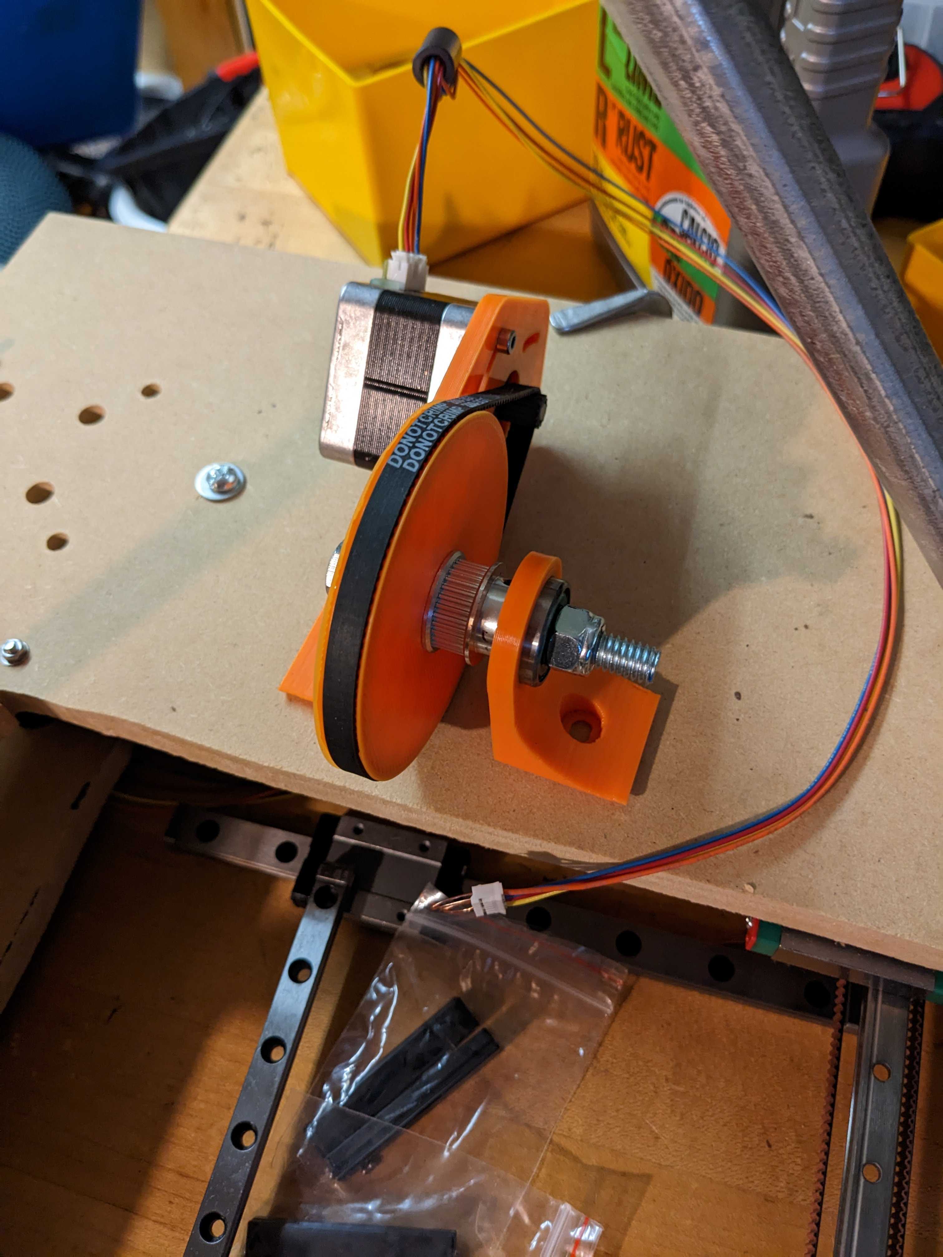
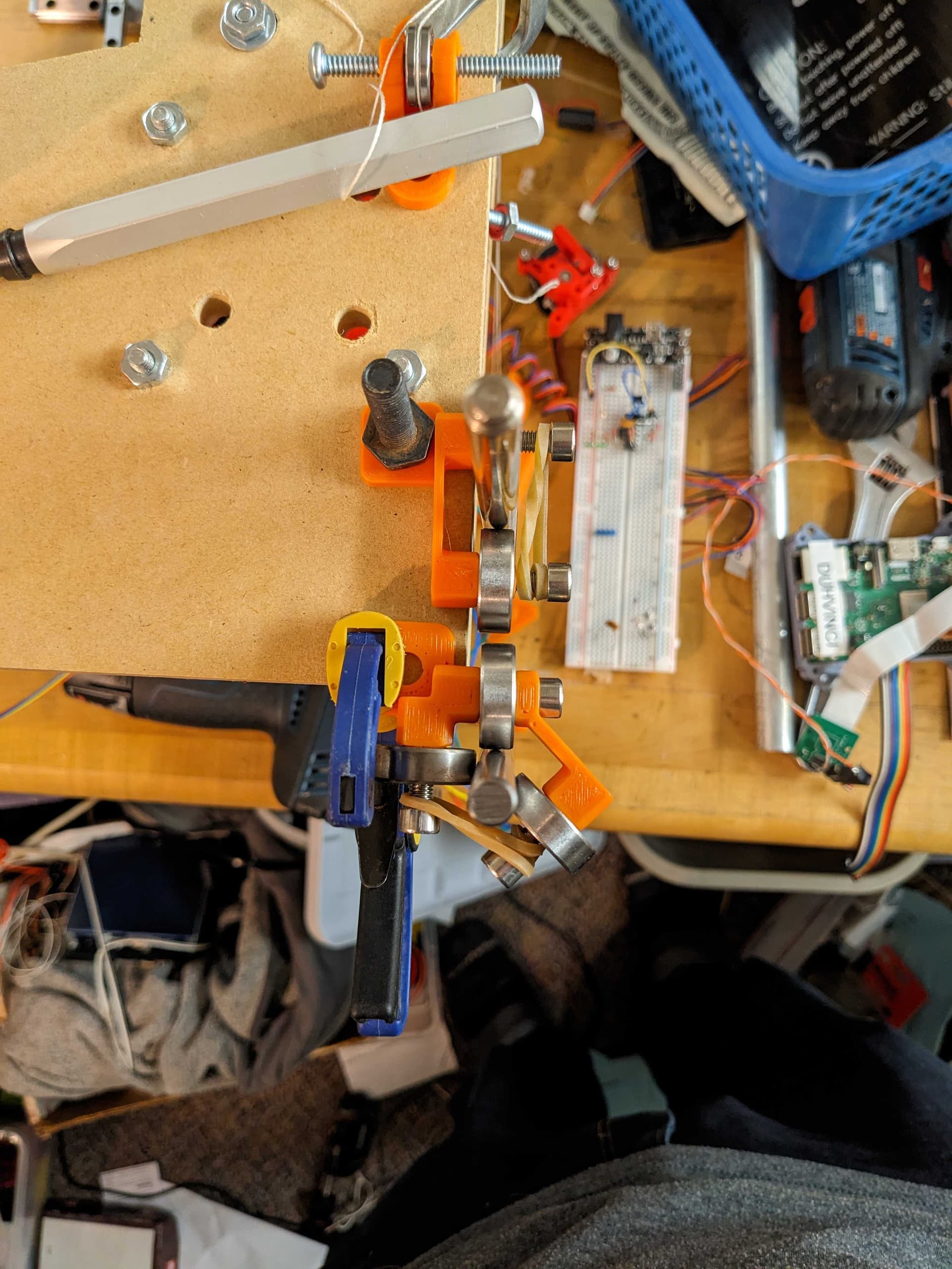
Redesigned the eccentric idler to accept a threaded stud (one side is self-tapping the other a slip fit). This keeps the two halves aligned and gives me something to grab on to to turn them.
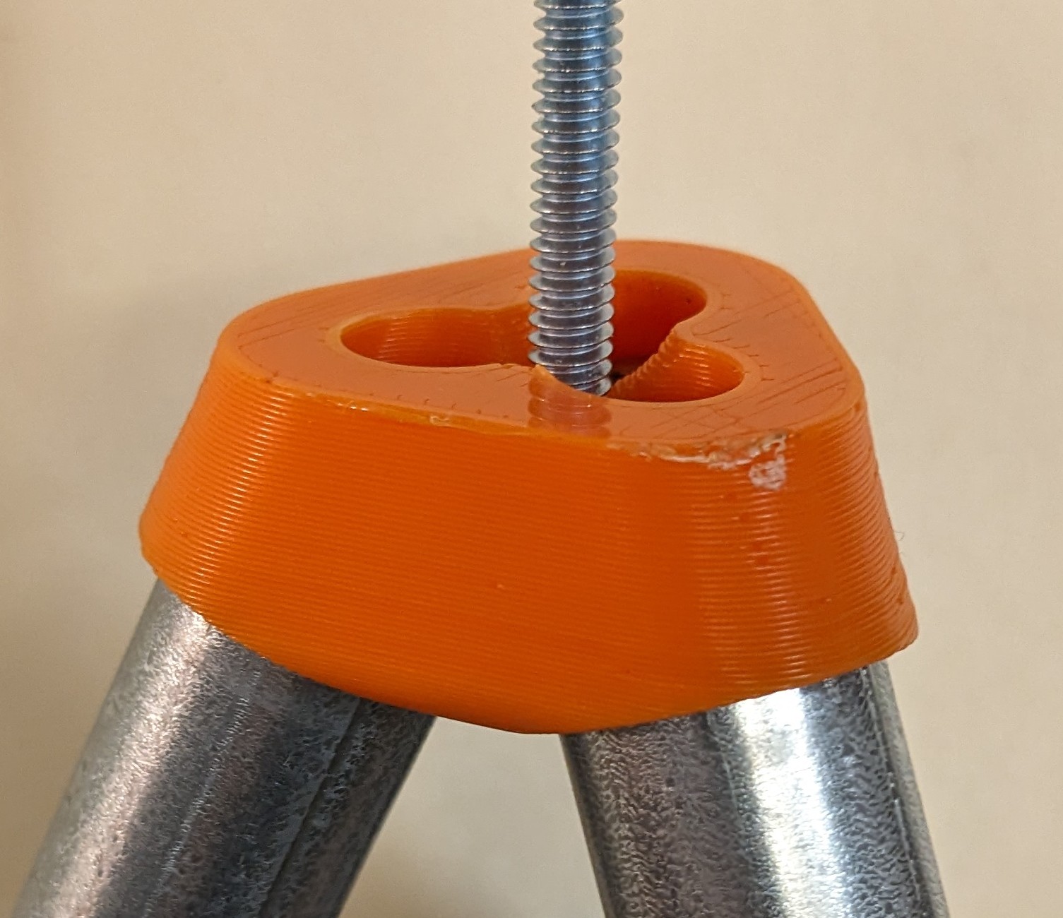
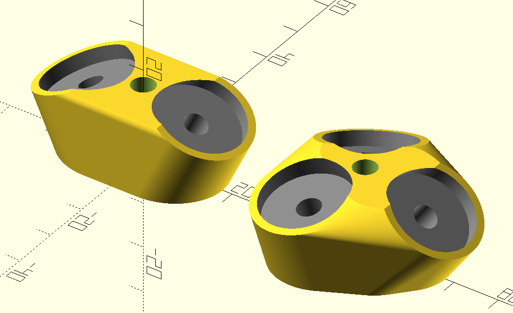
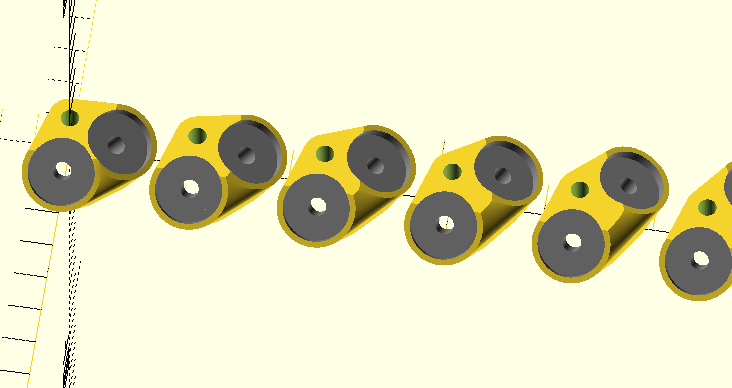
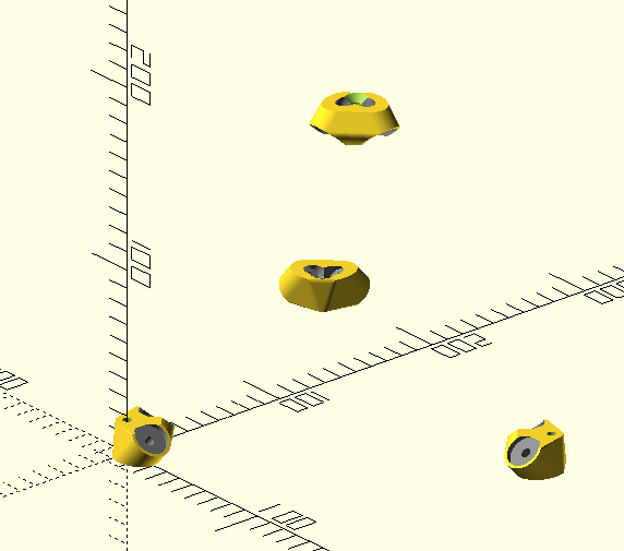
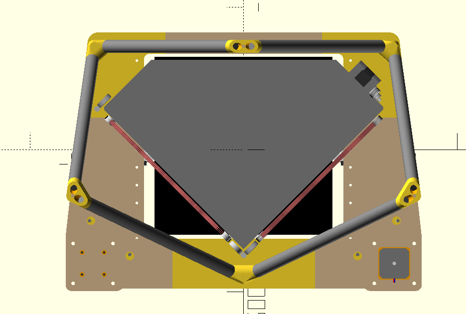
These corners can support up to three legs at nearly any azimuth+elevation. Only real limitation is whether the pipes would end up interfering with each other.
Now I need to write a small script to generate the appropriate azimuth+elevation given my desired corner locations. Finding the angle between points is simple, but because the pipes have non-zero diameter and have to be moved outward to accommodate the central mounting screw the angle has to be adjusted to accommodate. I also need it to spit out the pipe segment lengths so I can cut them correctly.
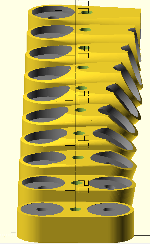
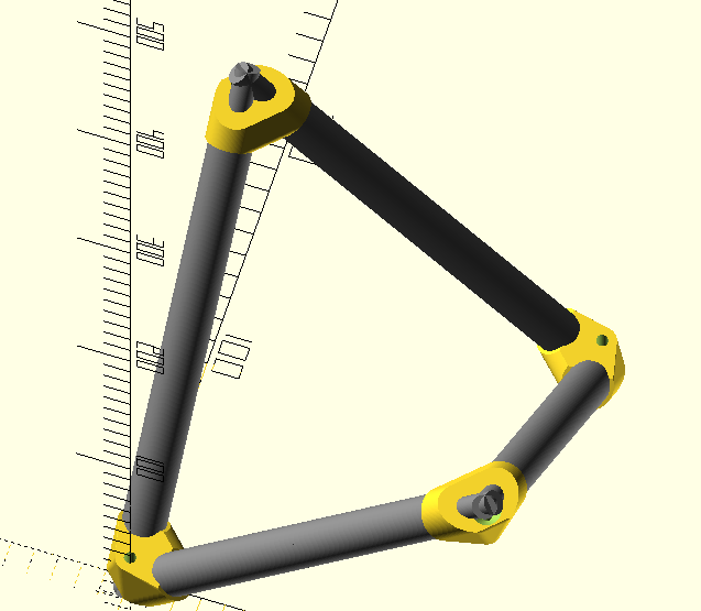
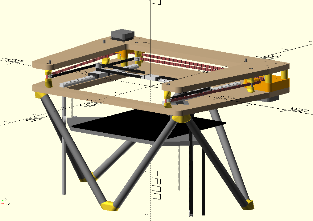
I did some work the past few days on a Perl script to do the work described above. I have a few off-by-N errors to chase down where things don’t end up exactly where expected, but I am able to make things like this by just giving the script a series of XYZ coordinates to join together:
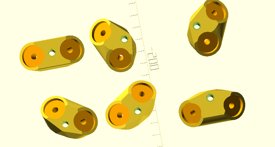
I put a small identifying N-gon around the mounting hole for each corner piece starting with a triangle and going up to a nonagon. Otherwise it would be quite hard to keep them all straight.
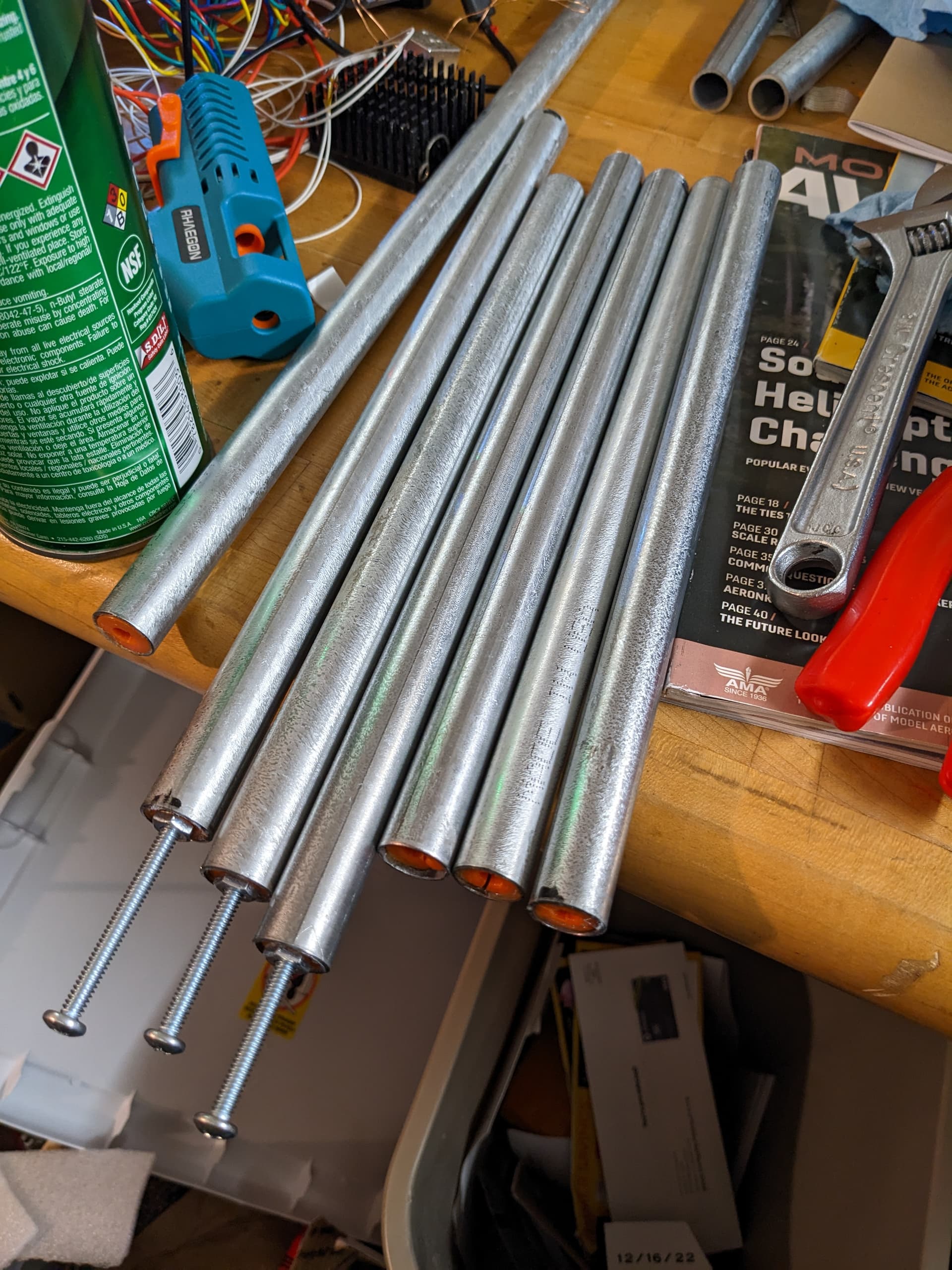
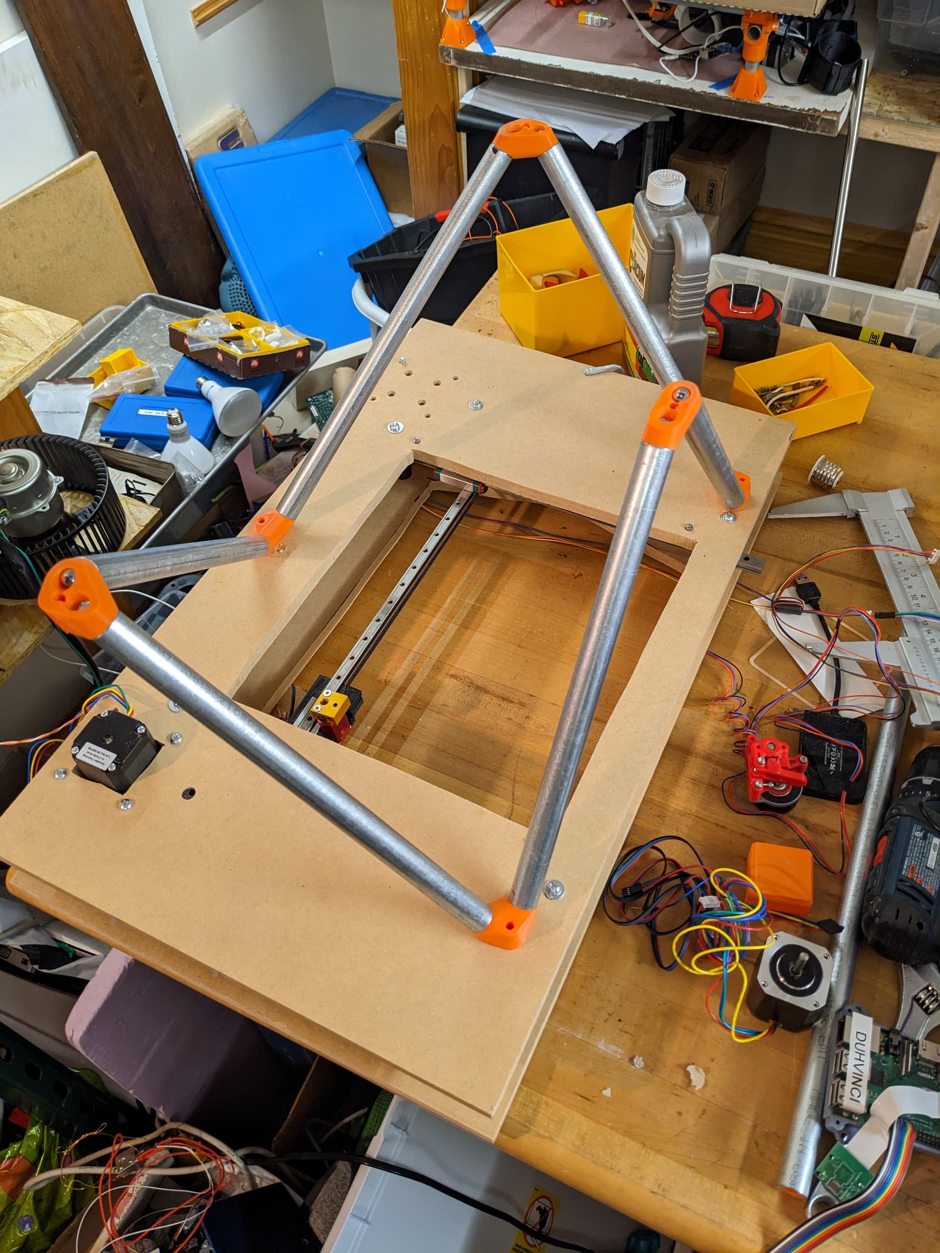
After a near disaster where I was generating a frame for the wrong size machine (I had changed the configured rail lengths at some point so my frame would have been too small) I got the corner pieces printed, measured and cut the EMT, and epoxied captive nuts into both ends.
My tubing cutter didn’t make all of the ends square so I want to contrive some way of evening them up before assembly. I can’t assemble it now anyways since I want to give the epoxy a chance to really set before stressing it.
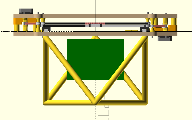
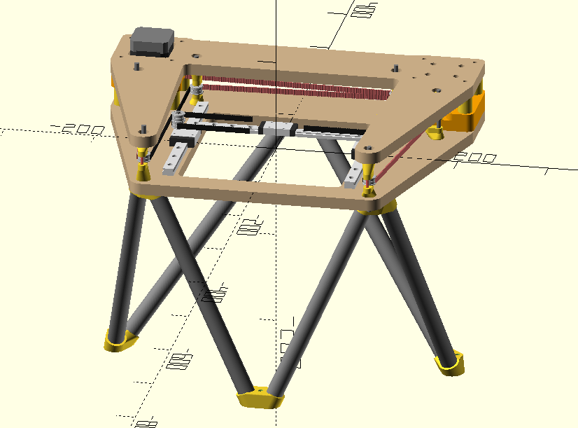
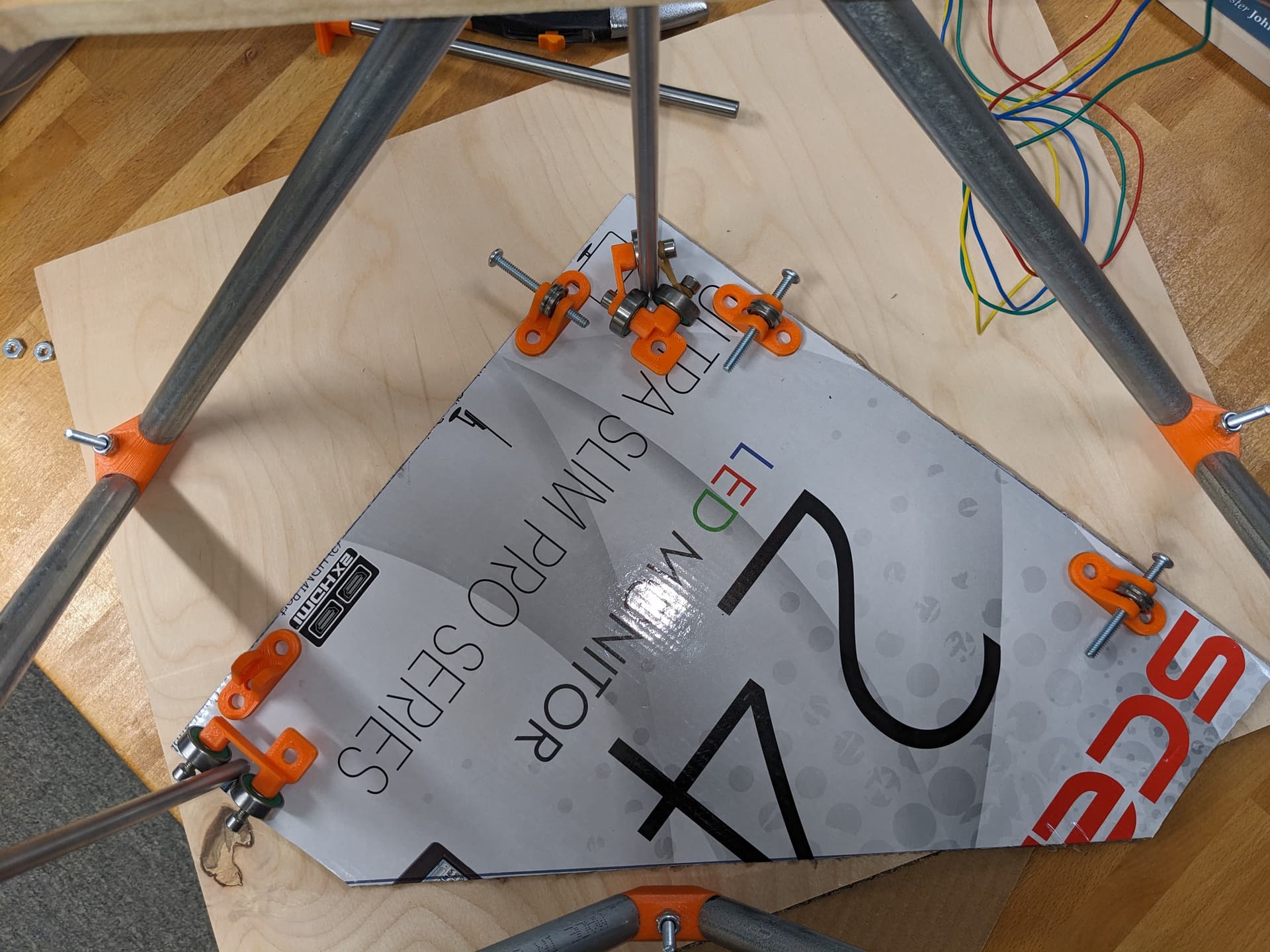
Switching my focus for now to a draft of the Z-axis. Rough shape is coming along but I still need to settle on locations for the various bearings and then create parts to actually hold the hardware.
Need to install a bottom plate to the frame, create a lower belt idler for the Z, mount the rods/cables, and make a Z stage to mount all of the bearing holders to.
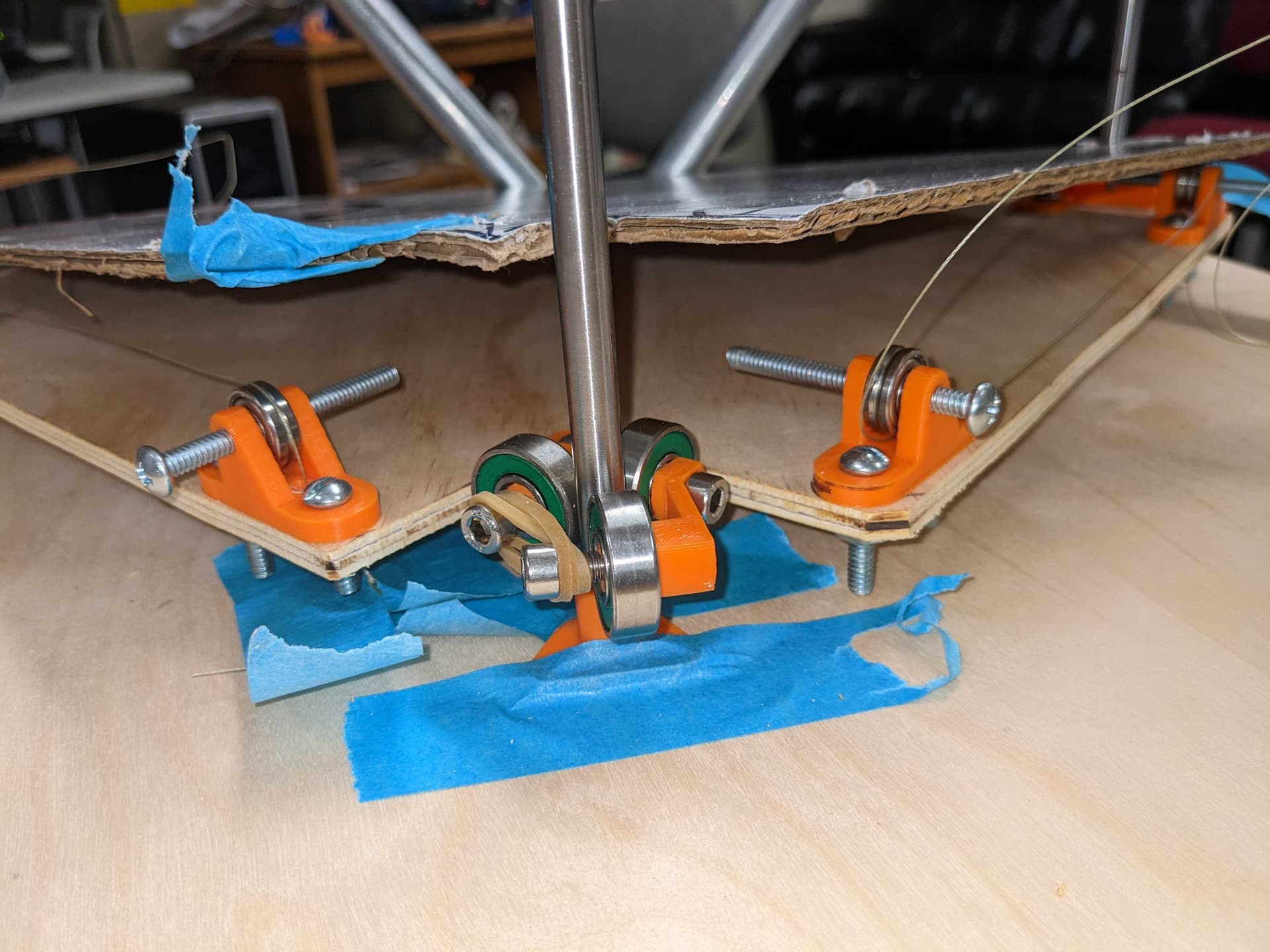
I did some more testing here and notching the rear corner really compromised the design because it moved the two opposed cables in that corner too far away from each other so there was a huge lever between them allowing the right side of the platform to be very springy.
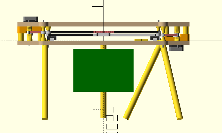
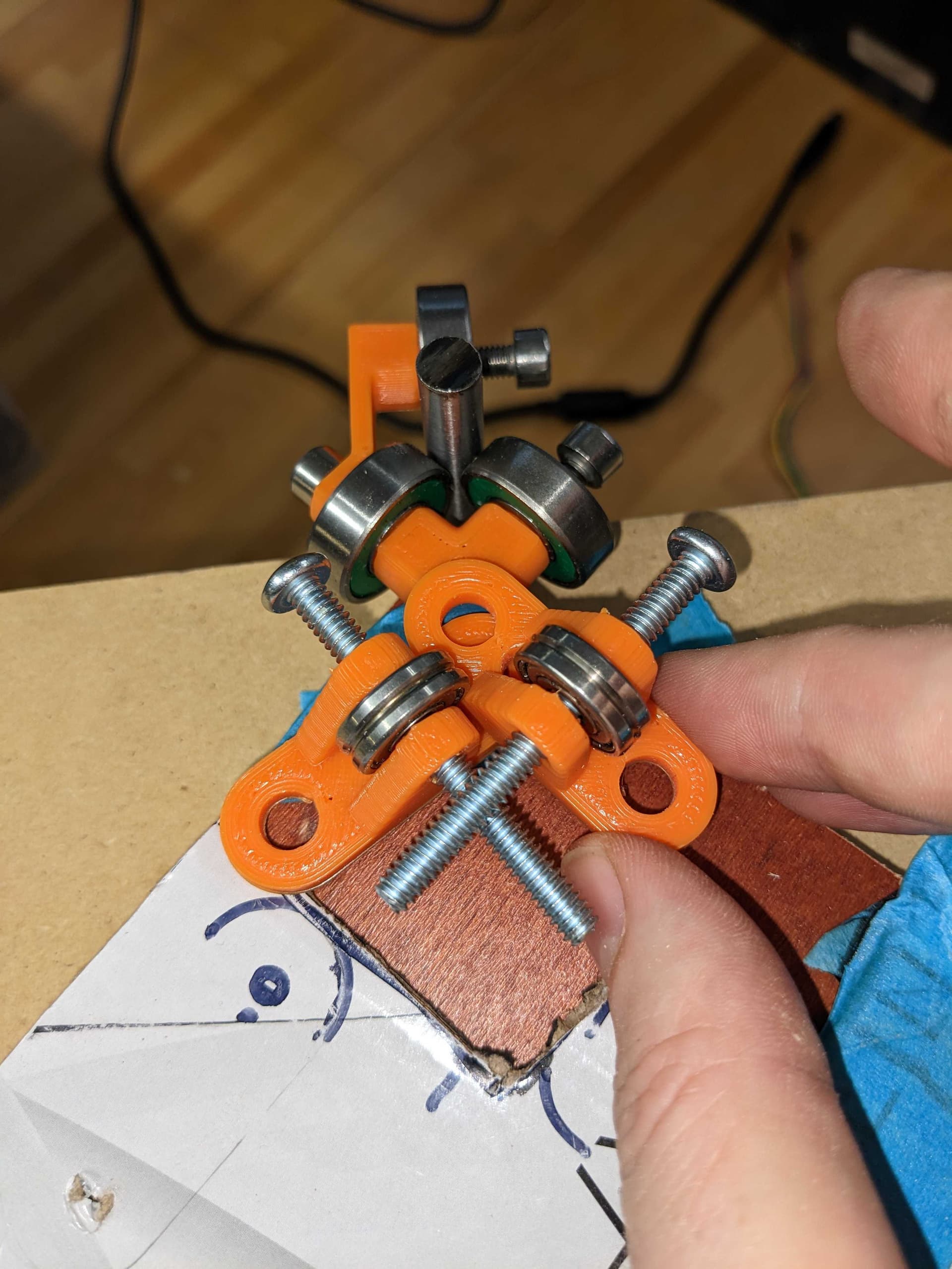
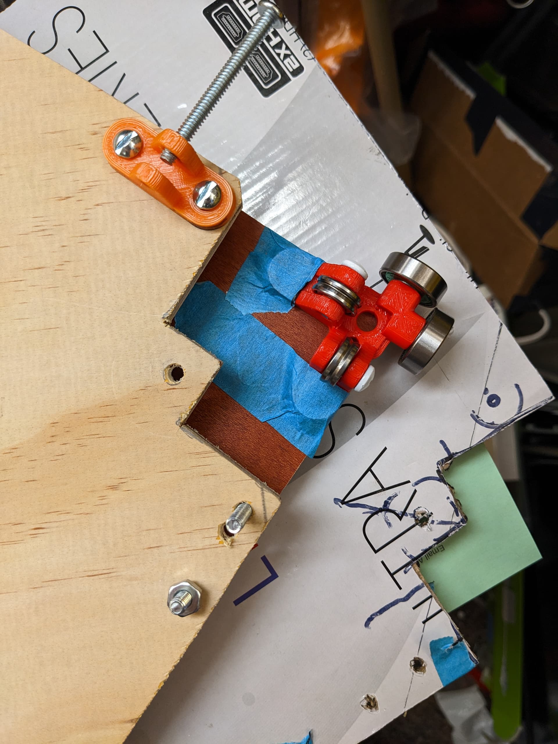
I’m trying a new revision where I have a sharp rear corner for the stage, a rear post that is outside of the printer’s frame (barely) and a unified bearing/pulley holder. Something like this:
Mounted the Z motor and gear reduction. Ready to drive this under.its.owm power now.
The far corner of the Z stage is still a bit springy, but a lot better.tham before. Might just run with this for a while and see what problems crop up (if any).