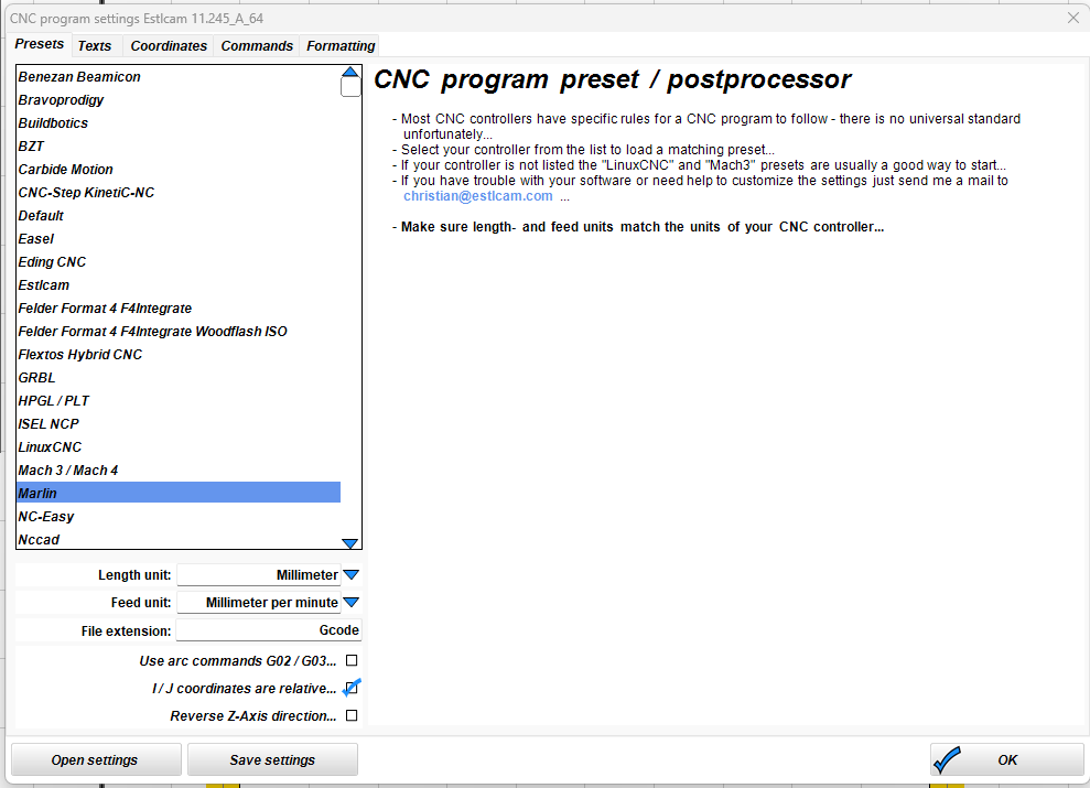
Marlin, same as Mike:
1 Like
Test cut with arcs turned off is done, I came up with a rectangle of 4.91x5.91"
With arcs turned on it was 4.88x5.88 so it’s a little better.
5x6in_no_arc.Gcode (18.5 KB)
1 Like
As far as I can tell, GCode still shows a move from X22.225 to X155.575, which is 133.35mm, or 5.25"…so something else must be up
Yeah, that’s what I saw as well.
Not to give up here, but maybe it’s time to install that Jackpot Board I just got and give GRBL a try.
1 Like
If you have one handy and it’s not much trouble, that would at least eliminate firmware/board and let you know for sure its mechanical if it still persists after swapping
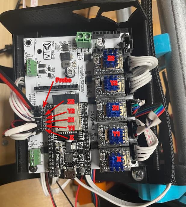
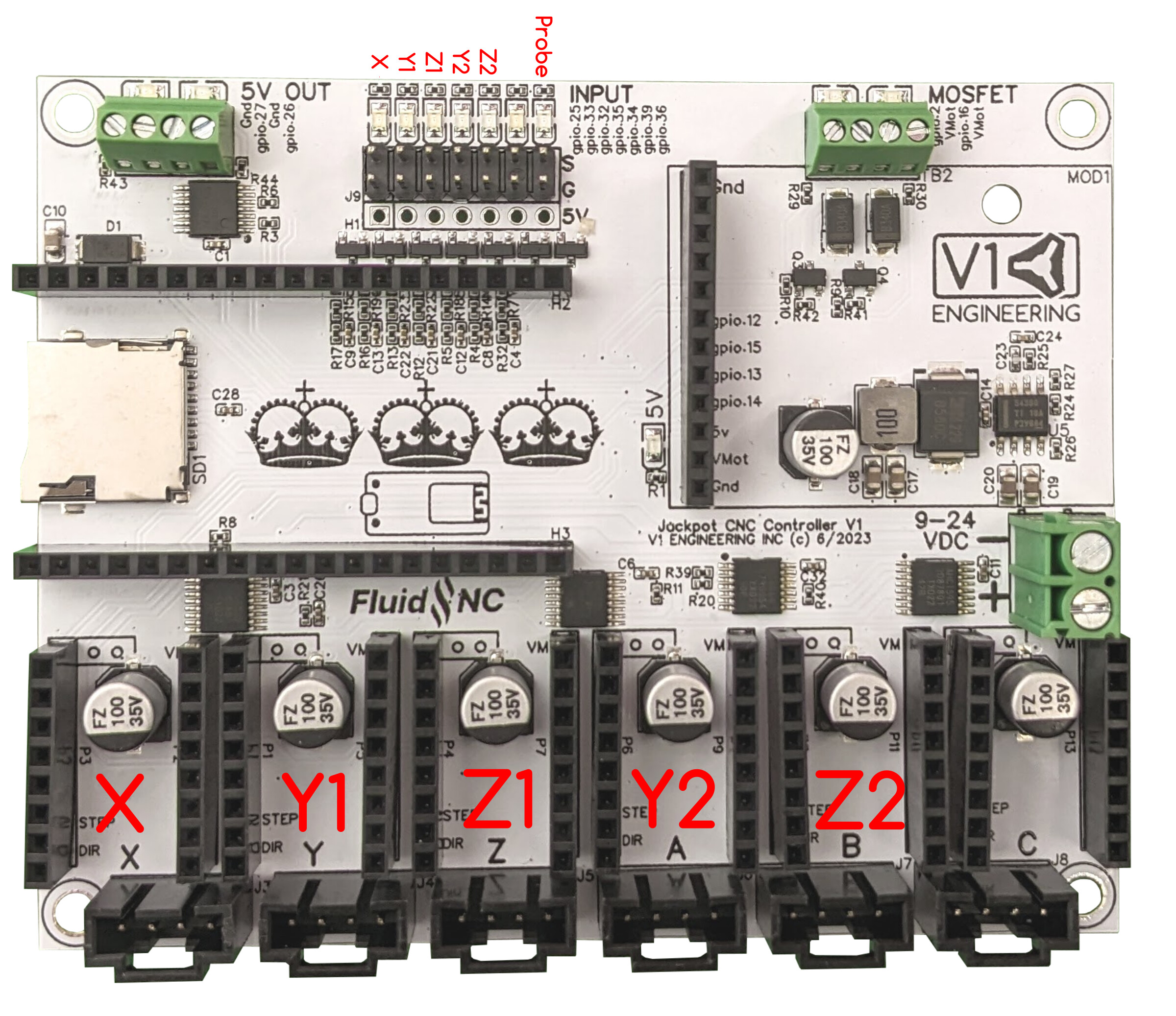
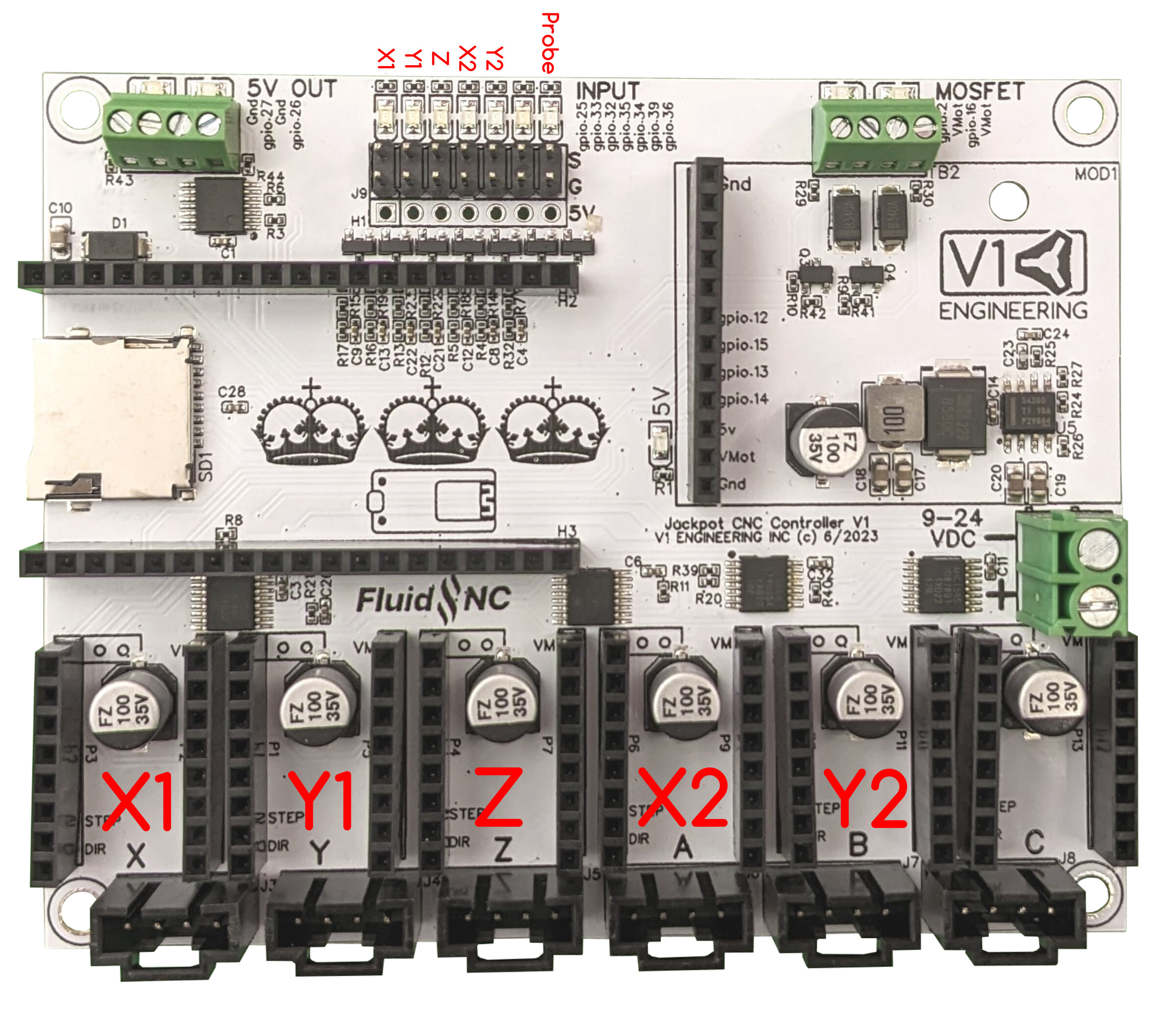
Not to get too OT here but I couldn’t figure out where to plug the endstop switches in.
The page for it says pics coming soon.
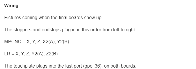
Jackpot CNC Controller - V1 Engineering Documentation
If I start down the trial and error road, I’m bound to fry the board
1 Like
I think it’s good. Basic confirmation I was placing them in the right spot was about all I was looking for outside of what was already there.
2 Likes
Maybe goes without saying but for noobs it could be helpful to be explicit.
LR3: X min, Y1 min, Z1 max, Y2 min, Z2 max.
MPCNC: X1 min, Y1 min, Z min, X2 min, Y2 min.
But it wouldn’t necessarily have to be in the diagram.
1 Like
It did already say
My issue with it as a noob, was it wasn’t clear to me which side was left or right, so I was concerned about screwing something up. The steppers were easy because it was the only one with drivers in it, but I wasn’t for sure which side to start on for the endstops, and wasn’t sure about wire orientation and whether it mattered if the plugs were flipped.
But looks like Ryan already updated the docs with the new pics for both, so I think it would have been much clearer for me with the way it is now.
(Although it does still say “The touchplate plugs into the last port (gpoi.36), on both boards.” @vicious1 )
I added it to the docs with the machine name under it.
1 Like
What part of that isn’t sitting right with you?
These are great. Sometimes when a wire comes loose, I’ll just google search for these wiring diagrams so it would be useful if you put “LR3” or “MPCNC” on the image so it’s immediately obvious when they get surfaced in a google search.
Also - are those JST-PH sockets for the steppers? May want to list that - sorry if you already have.
THANKS!
1 Like
gpio.36 rather than gpoi.36, right?
2 Likes
Ohhhhhhh yup, that dern spelln’ get me again.
2 Likes
So, the solution turned out to be to install the Jackpot controller I just got. Unfortunately, I didn’t ever quite solve the 1/8" accuracy issues I was having previously when running the SKR Pro (I’m guessing I probably made an error when compiling Marlin, that’s about the only thing I can think of), but I’m happy to report that the jackpot works great, and my tests are now coming out within .05" accuracy! I did a pretty rushed squaring on the machine so I may be able to get that error down a bit but I’m pretty happy with it.
Thanks everyone!!
4 Likes
Nice, you should pretty easily get below that as well. Feeds and speeds play a role, make sure you use a full depth light finishing pass, and boom, real low numbers. 0.5mm should be easy and under that once you get your feeds and speeds dialed in.
3 Likes
I was able to sniff out an error that was giving me inaccuracies on bigger cuts; This is probably part of the issue I was experiencing before, although the issues I was having when I started this thread were much worse…
To get to the punchline, part of my issue was my Y1 belt being too tight, in combination with the belt end stops being slightly misaligned. here’s a photo:
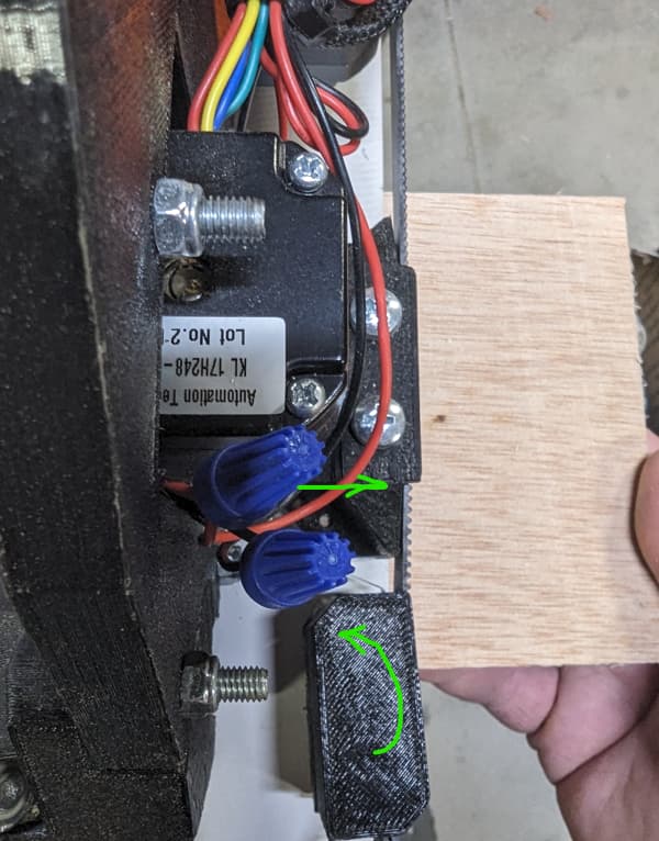
I added a couple of green arrows although it’s easy enough to see that the belt block had rotated a bit under the (over) tension of the belt, and then it created this issue where the lowrider’s Y1 motor /pulleys now sit proud of the belt rather than being perfectly in line with it.
As you may have seen in my previous posts, I was having a lot of trouble with 1/8" inaccuracies previously and thought it may be something to do with a bad compile I had done of marlin on my SKRPro, or something along those lines. After installing the Jackpot controller, I was able to cut out smaller test pieces with quite good accuracy, however, on larger cuts that got a lot deeper into the LR3’s X and Y travel, I was once again finding inaccuracies that were in the 1/8 to 3/16" range. After may attempts at re-squaring and a slight adjustment of the E-steps in both X & Y, I was getting dead accurate measurements between 3 of the 4 corners, but the side of the rectangle where the X axis was maxed out always gave me a measurement that was 1/8" too long and I just couldn’t get the diagonals to match. After loosening the Y1 belt, I finally got a perfect 90 degree rectangle with all four sides being accurate lengths.
I need to do a build thread, I think. This table was always meant to be a temporary setup which I would then use to cut out a Paulk style box-beam table, but I can’t seem to get around to it. I’m going to have to do some amount of re-building to address that issue pictured above, and sooner than later, so maybe I’ll give the Paulk setup a try!
3 Likes
closing old topic to help fight spambots