Long time listener, first time caller…
First off, I have to tell you guys about how much I LOVE this community. I am terrible with a tape measure and a saw… so being able to build myself a robot that makes the (accurate) cuts for me is a dream come true… I’m older so I’m pretty much all 2D cad but it’s just amazing that I draw something in CAD and then create it so effortlessly. Brilliant. Thank you, Ryan, and the V1 Community. This has been a godsend.
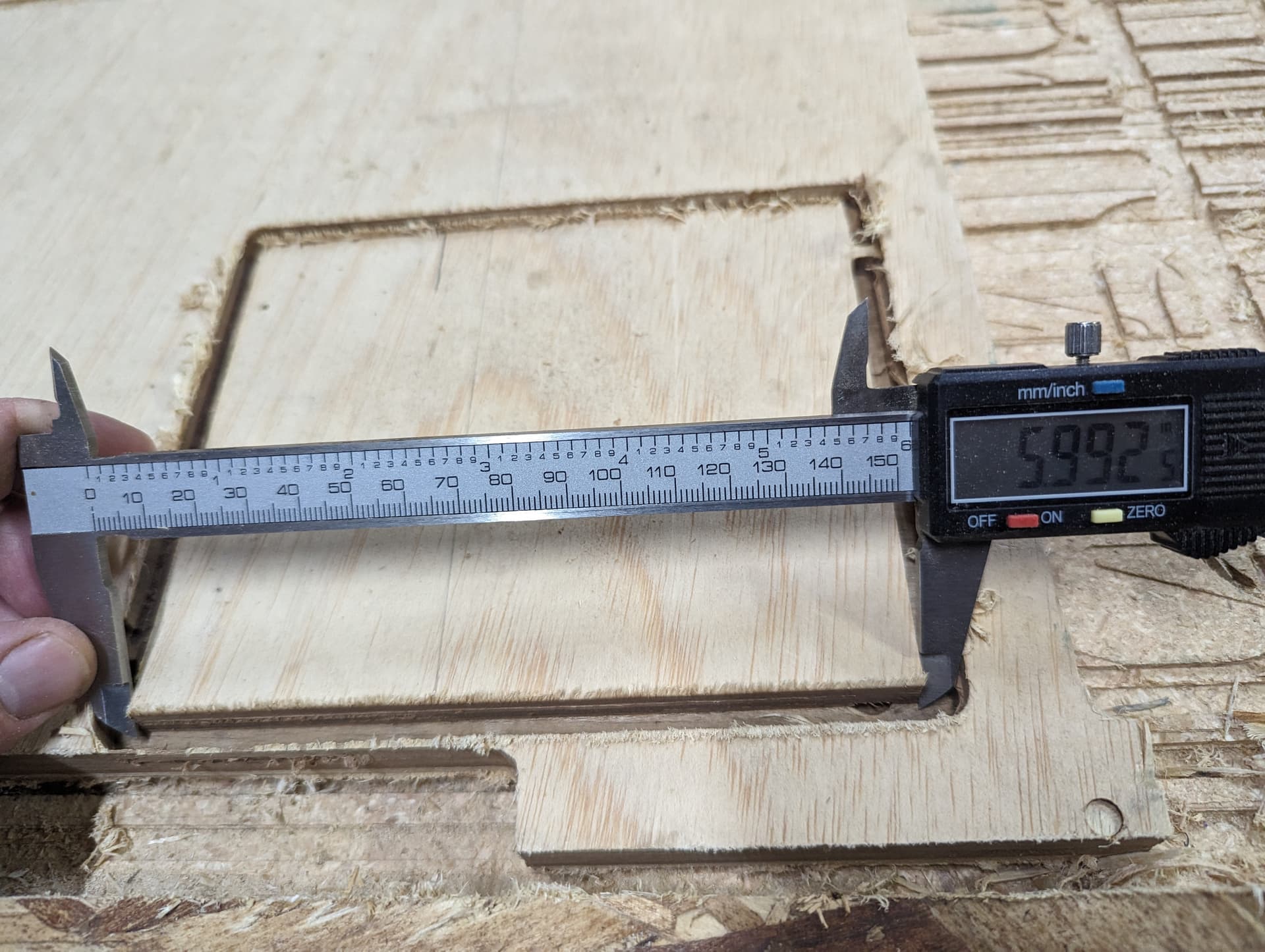
Alas, I’ve found that my LR3 is consistently making cuts that are 1/8" inch too short. I cut a part that was to be 53x47" in size and it was 53 7/8x46 7/8. So I grabbed a scrap, and had it cut me a 5x18 rectangle, but it came out 4 7/8x17 7/8. There’s a facepalm error that I’m making here but I can’t find it.
I had a lot of trouble with the wiring, but I think I have that all sorted out…I just went through the machine and made sure the belts and set screws were all tight, and tensioned. check. My build is huge, relatively. Eventually I want to build myself a Paulk workbench that can accommodate my LR3, that can then accommodate a 5x5 or 4x8 sheet of plywood. So, my current table is 6’x12’(roughly). However, I have gotten it down to <1/16" difference between the diagonals so I don’t think it’s due to a lack of square.
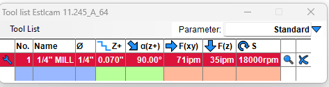
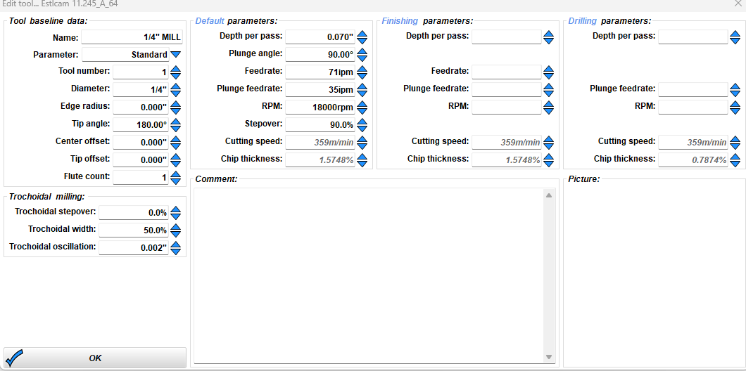
I am using a 1/4" dia. router bit, and I have set my EstlCAM tool up as 1/4" dia., but it just seems like it is thinking I have a 1/8" bit. I will attach screen shots of my tool setup with EstlCAM .
I’ll keep digging away, but you all are smarter than me, so any ideas?
In case it matters:
I have the Makita router, SKR Pro (but I’m printing out an enclosure for the Jackpot controller that I just purchased from Ryan, so that’s about to happen).
for what it’s worth, I’m cutting mostly plywood and OSB so if you have any pointers on my settings, feel free to let me know. I haven’t had a chance to dig into this part of it much, yet… Thank you.
That out of the way I believe I’ve read that for dimensional accuracy it’s best to include an allowance and then to a full depth finishing pass. Stay on the line caller, someone who actually knows what they’re talking about will be along shortly.
A consistent inaccuracy can have more than one cause.
The concept of the bit being a different size than what you have it described as is one possibility.
Another possibility is that your E steps need adjusted in the firmware. This is a setting that tells the stepper motor how far to spin in each “step.“ The goal is that if you tell the machine to move 600 mm, it moves 600 mm — not 590. If it’s consistently moving less (or more) than you tell it to, you can edit the E steps for that given axis to fix that.
Is it making short cuts in all three axes? Are only in one direction?
I don’t know how you have set things up in CAM, so this may be completely off base, but the amount of error is 1/2 the diameter of your bit, so it may be that the CAM is cutting with the bit centered on the cut line, rather than offset to accommodate the tool diameter.
Yeah this seems likely. I pasted a screen shot of my Estlcam setup in the second post because it really seems like I did something wrong here. But I did put the bit as 0.25" in Estlcam… unless there’s somewhere else where I need to change that setting - other than the estlcam tool list?
yeah, I got these bits off of amazon so I suspected they weren’t accurate, however they did come out exactly 0.25" when I checked them with my calipers.
Can you show a screen shot of estlcam where you have defined the toolpaths? When you choose “part” they should be outside the rectangle you are trying to cut.
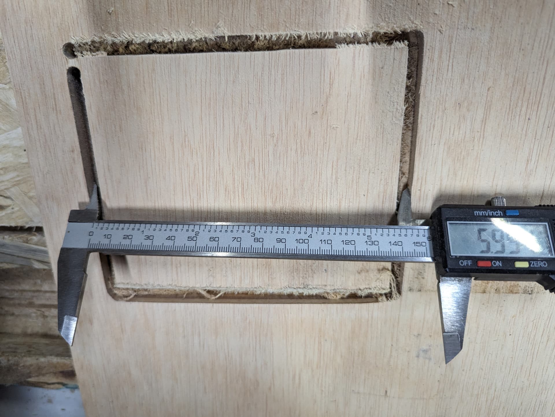
This has to be the issue; I just can’t find the setting where I specify that the toolpath is outside of the drawn shape when I select “part” in EstlCam. I just did an experiment where I had it cut a 5x6" hole instead of choosing Part, and it gave me a 5.999" cut, measured with my caliper, which is amazing.
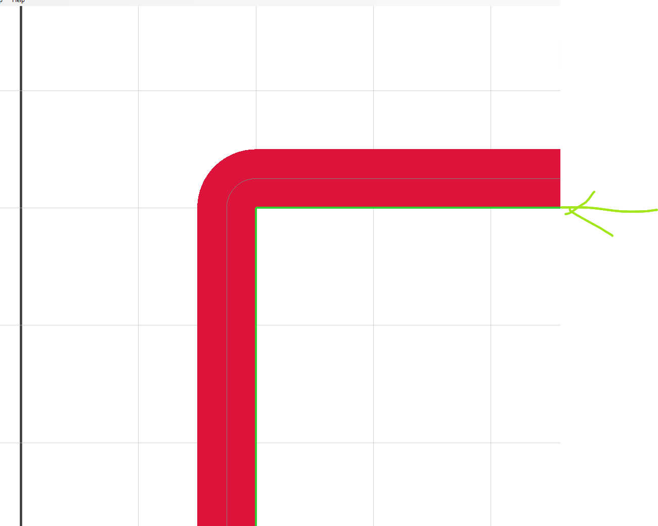
I’ll keep going through the EstlCAM settings and see if I can get the “part” selection to work the way I’m expecting it to. Graphically, when I choose a part it shows the toolpath correctly, all the way outside my drawn shape, but then it’s centering the toolpath on the drawing rather than cutting it out properly.
I’m completely unfamiliar with CAM in general, and ESTLCam in particular, but is it possible that you are using a finish pass that is removing material from the part after the rough pass removes the material to the edge of the designed part?
It would be interesting to see what would happen if you set it up to use a larger bit (1/2" ) in foam to see if the dimension is then out by 1/4", or if it is still out by 1/8"
Well I haven’t solved the problem yet but I found a work-around. I’ll just offset my drawing 1/16" before loading it into EstlCam and then the LR3 cuts it out perfectly. It also works perfectly for the Holes function, it’s just the Part function in EstlCam.
I’m blown away with these results, here’s what my LR3 cut for a 6" wide hole:
It could also be that the core is loose, wobbling left to right. So if it goes to the left, it tilts as well so that the cut is short, tilting to the other side when going the other direction. Are the cuts only off on X, or also on Y?
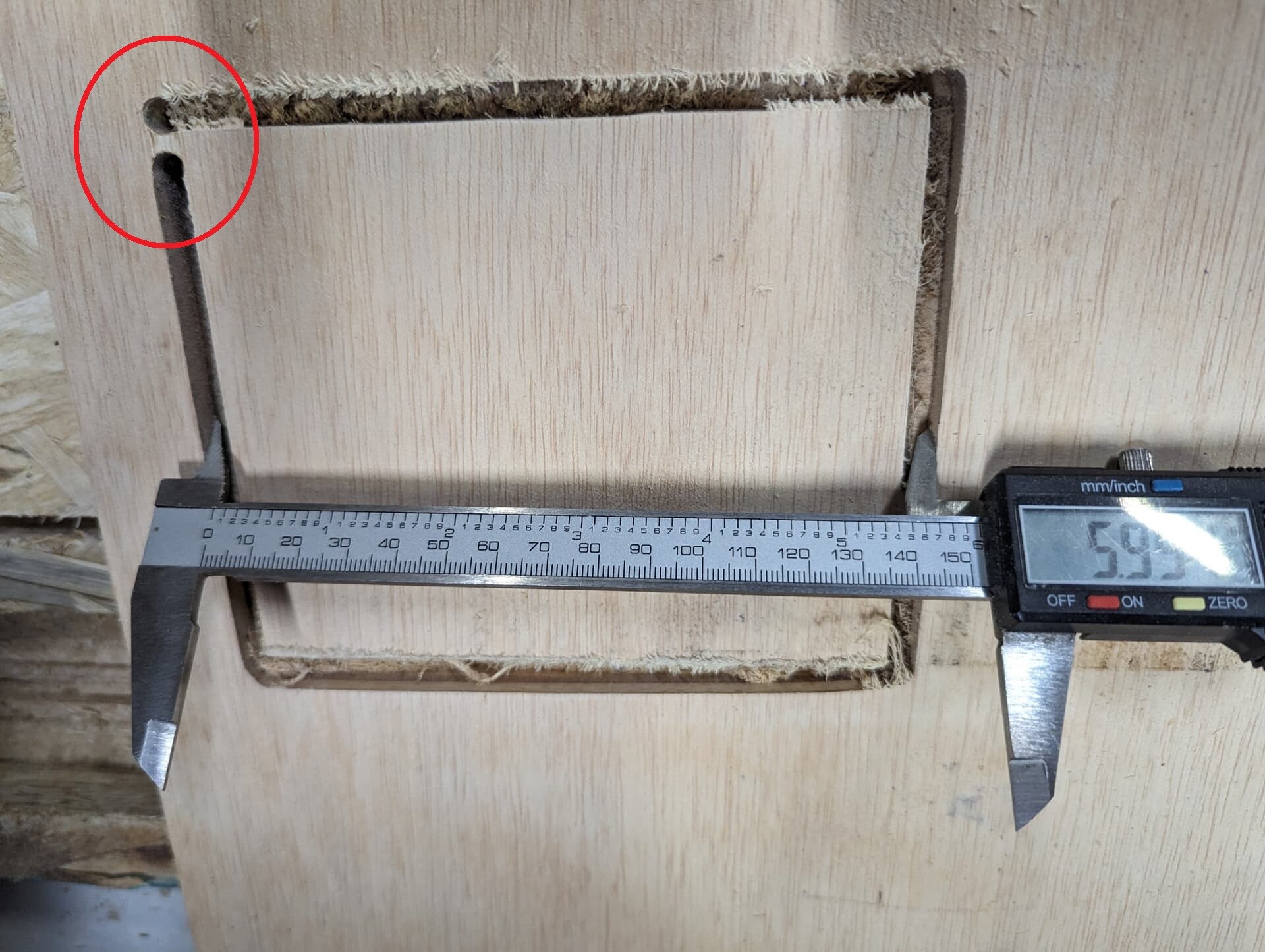
What’s up with the circled area? Estlcam likes to close its paths, but this obviously isn’t.
This speaks to some sort of movement of the machine that it isn’t designed for. I see a similar artefact in the other picture as well. It looks like the shape isn’t properly closed.
The above response about the core possibly being loose and allowing movement seems like it could be, or else the belts are loose and have slack. Either way, this doesn’t look like the hardware is correctly set up.
That is in fact a holding tab.
I’ve been over all the belts and grub screws so there are definitely no loose parts at this point. In fact it’s cutting very accurately.
I’m convinced that when I select "part* in estlcam it’s center in the toolpath on the line instead of cutting the edge of the line. In other words, it’s reducing the size of my part by 1/2 the width of the bit.
Here’s the Gcode of my test part, it’s a 5" wide (X) by 6" tall (Y) rectangle:
Gcode looks okay. If you had a pen it would draw a box (with rounded corners) and the dimensions would be 5.25 x 6.25 inches.
I also checked to see if soft stops might be clipping your movement, but since movement is all positive, don’t think that’s possible. If the rectangle origin were (0, 0) then the bit would need to go negative by half the width of the bit and clipping to 0 could have an effect on a part but not on a hole.
Having ruled that out, my conclusion is that what you are seeing is not possible.
Sheesh, well that’s weird.
Given that my bit is 0.25", shouldn’t it put the center of the bit at 5.125x6.125" ?
When I redrew the box 1/8" bigger in CAD and then ran it thru EstlCAM and the LR3 it gave me my almost exactly 5x6 box.
The other thing that is strange is that it is always 1/8" off, I had the same 1/8" error on a part that was to be 53x47" overall.