Did you test your e-steps yet? Is the inaccuracy in all axes? Only x and y? Only x? Only y?
Doug, I haven’t checked e steps yet.
I’m getting the same 1/8in inaccuracy on a 5x6” rectangle as I am on a 53x47” workpiece. Both 1/8in off… and same inaccuracy in both x and y
Can you please confirm this, please? I would like to help but you are ignoring every second post. ![]()
sorry, thought I answered this. There’s no play in the core top or bottom.
1 Like
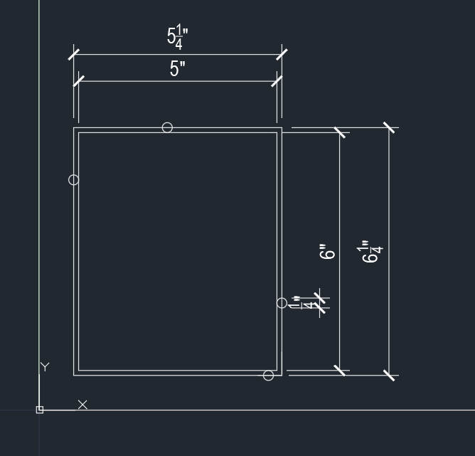
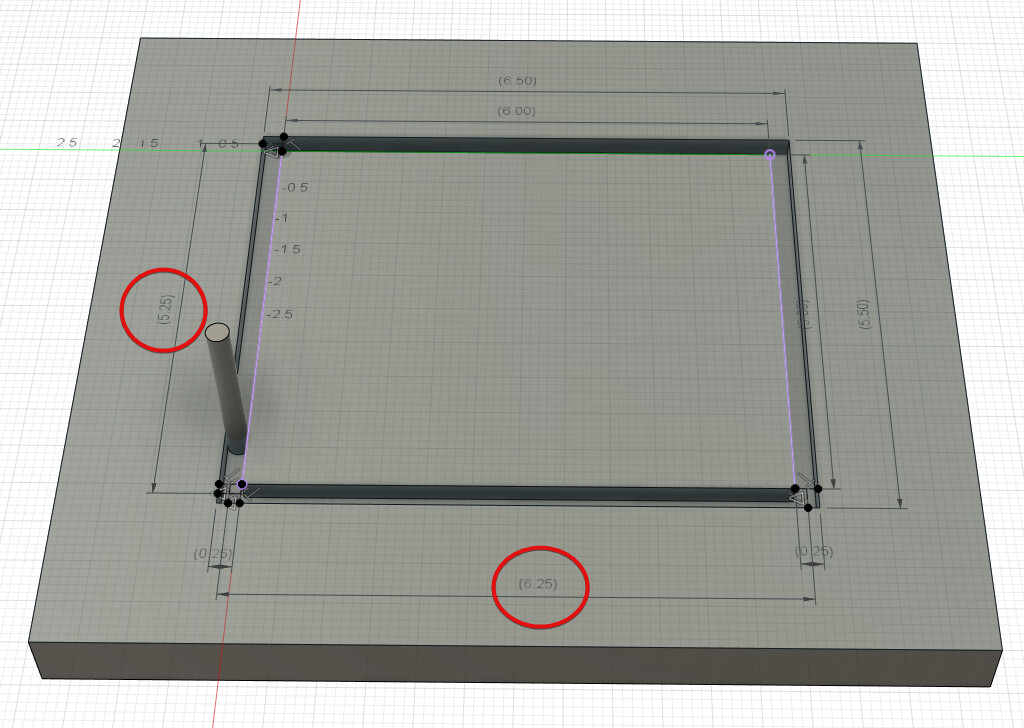
The center of the bit needs to traverse 5.25 x 6.25 because the radius of the bit is taken from each side. Ideally the bit center would traverse 5.25 x 6.25 and leave a 5" x 6" part and a 5.5" x 6.5" hole in the scrap.
It is as if you are losing the radius on one side only, which is part of what makes it so weird.
Maybe a 5" circle would indicate something. If you are running into soft stops then you would see flat spots on two sides of your circle but the diagonals would be the right dimension. A smashed rectangle is still a rectangle and it’s less obvious what is happening.
1 Like
If it should be traversing 5.25x6.25, then it is a Gcode/EstlCam issue: I pasted a block of the gcode from estlcam into excel and converted the mm values to inches, there’s a 1" offset from 0,0 for both x and y, so therefore it’s traversing 1/8" less than it should on both axes.
SO… the error is indeed coming from EstlCam. Probably something that I’m doing.
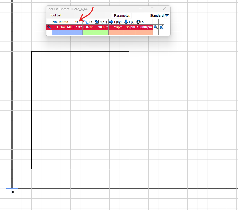
I think that I have my tool correctly defined as .25" diameter, but there must be something else that I’m missing.
OK, so checking for an e-step issue is fast, easy, and would definitively allow you to rule out a possible cause.
You can use your interface (usually a touch screen but could be pronterface or repetier hose or estlcam) to tell your machine to move a certain distance (longer is better), and measure how far it actually moves.
This can be tested and adjusted per axis.
One way to do this is to attach a pen, and lower the core until the pen is touching a paper, and then tell your machine to move say 100mm in x (or 200 or whatever) and then measure the line.
If it is correct, then you have ruled out that e-steps needs adjusted, and it would lend support to the hyopothesis that an ESTLcam programming glitch is a possible cause.
However, I think I read above that Jamie checked your G-Code file and said it was correct, so that tends to rule out the hyopothesis that an ESTLcam programming glitch is a possible cause.
Maybe this will help clarify what @jamiek is saying
The red highlights are the dimensions of the center of your tool passing around the outside.
( Well…where they should be ![]() )
)
Just figured out how to quote other messages. woohoo.
Thanks, yeah once I sketched it up, it made more sense to me.
I did an 1100mm move in both the X and Y axes and came up with 43.25" which is about1098.5mm; seems decent?
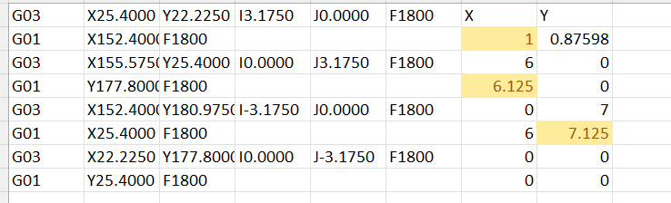
I don’t have a good grasp at reading Gcode but if you look at the file I posted, it looks to me like it’s actually moving 5.125x6.125, not the 5.25x6.25" it should be (I started the rectangle at the coordinates 1,1):
I’m only slightly familiar…I’d have to defer to someone here with more experience
The G03 commands are the rounded corners. If you ignore the I and J parts, the X and Y determine the endpoint of the arc. The extreme X and Y values occur at the ends of the arcs. The extreme X values are from 22.2250 to 155.575 which is 5.25 inches. The extreme Y values are 22.225 to 180.975 which is 6.25 inches.
But maybe somehow the G03 commands are getting dropped? That might lead to a behavior like you are seeing, although I would expect it to truncate both sides by 1/8" for a 1/4" total width error. It would be consistent with a problem appearing on parts but not on holes.
Did you compile your own firmware?
You can try disabling arc commands in EstlCam and it will produce many short segments at the corners instead. Maybe that fixes it.
1 Like

I just loaded the GCode and was wondering the same about the arcs…
Seems like I’ve read a few times where Arcs have caused problems
So that is decent, and you can edit the e-steps in your Marlin settings (if you have a touchscreen you can use it) to get closer to perfection. There is a formula provided on a Teaching-Tech calibration site for how to calculate what your new e-Steps settings need to be, based on how far off you are.
Some thoughts:
The small amount by which you are off means the e-step calibration is not responsible for your short cuts.
The earlier post by Jamie, I must have misread, as I thought your G-Code was good, but based on your recent reply, apparently your gcode is not good. This seems to support your theory of the issue being with ESTLcam as being more likely.
I am curious of whether operating in imperial (inches) as opposed to metric (mm) might possibly be of note. I am not positive, but I think many of us do CAM work in metric. Do you get the same error if you output in mm’s?
UPDATE: just saw where Jamie pointed out that when the arcs are taken into account, the distance is correct, so may be an issue with the arcs command being dropped.
This sounds like a decent workaround!
I changed the workspace size in the config file, so yes.
EDIT: NEVERMIND I FOUND IT - I WAS SUPPOSED TO UNCHECK “USE ARC COMANDS G02/G03” BOX ON THE CNC PROGRAM SETTINGS IN ESTLCAM
I really need to get a metric tape measure…
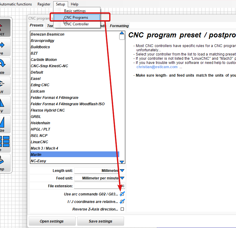
Thanks Mike. I’ve unchecked it and am running a test cut now…
1 Like
I was just coming to post the same type of graphic. You beat me to it.
Zac, notice in the graphic that Mike has “Marlin” selected for his CNC program preset. What selection do you have there?