I think I got everything I need and can play with this tomorrow.
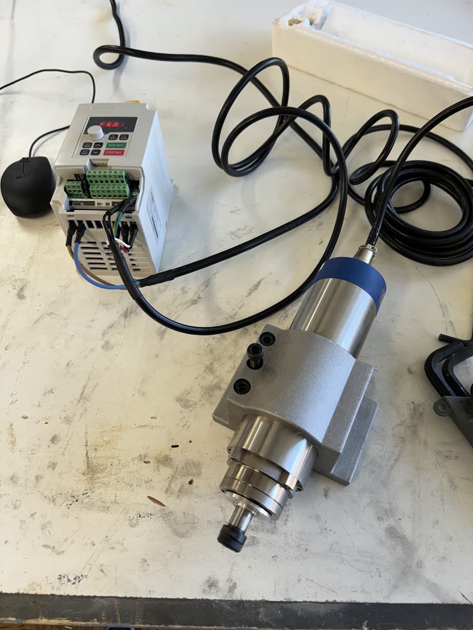
My first reactions to the spindle - this think is heavy and chunky. I am pretty excited
I think I got everything I need and can play with this tomorrow.
My first reactions to the spindle - this think is heavy and chunky. I am pretty excited
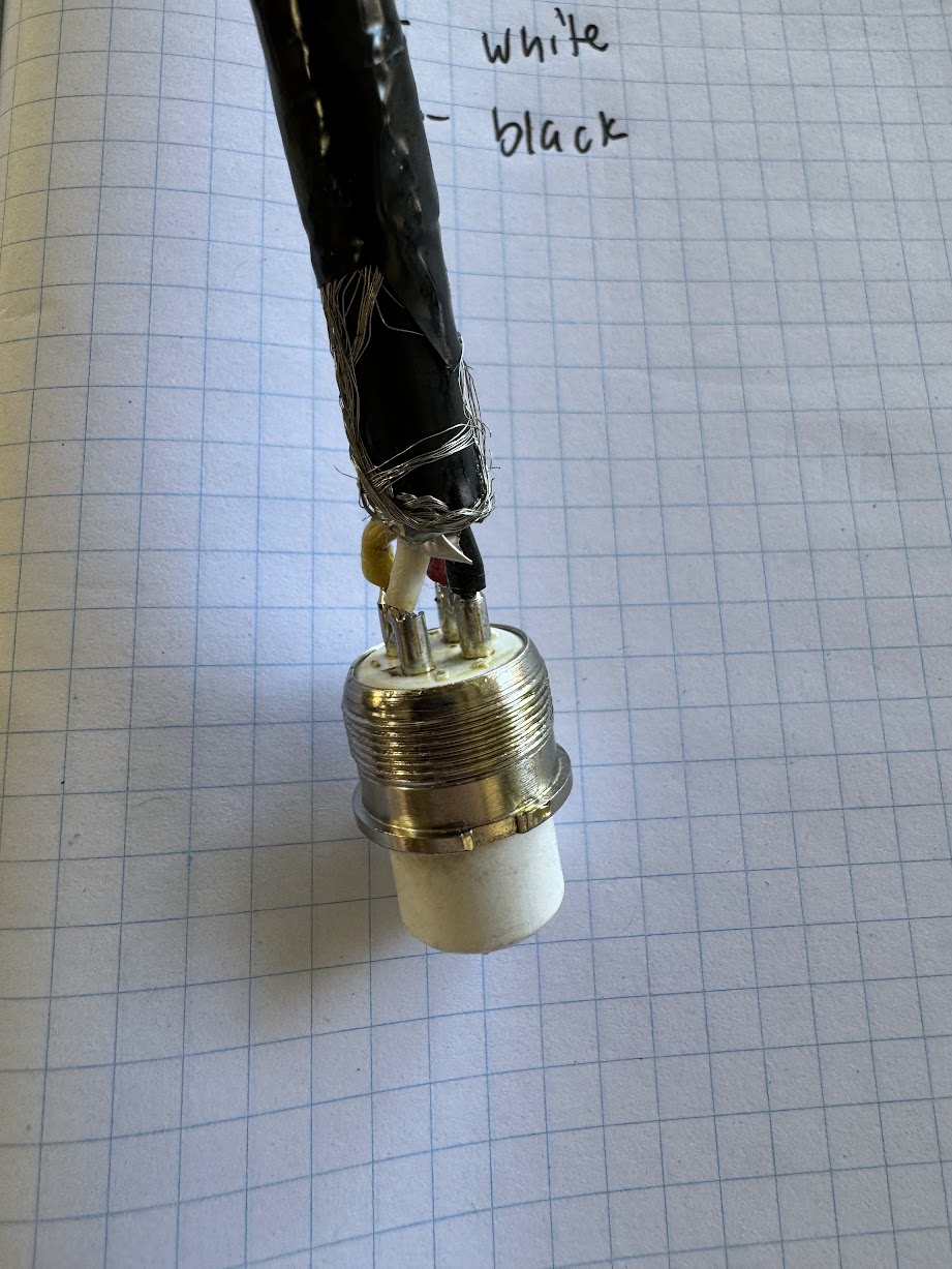
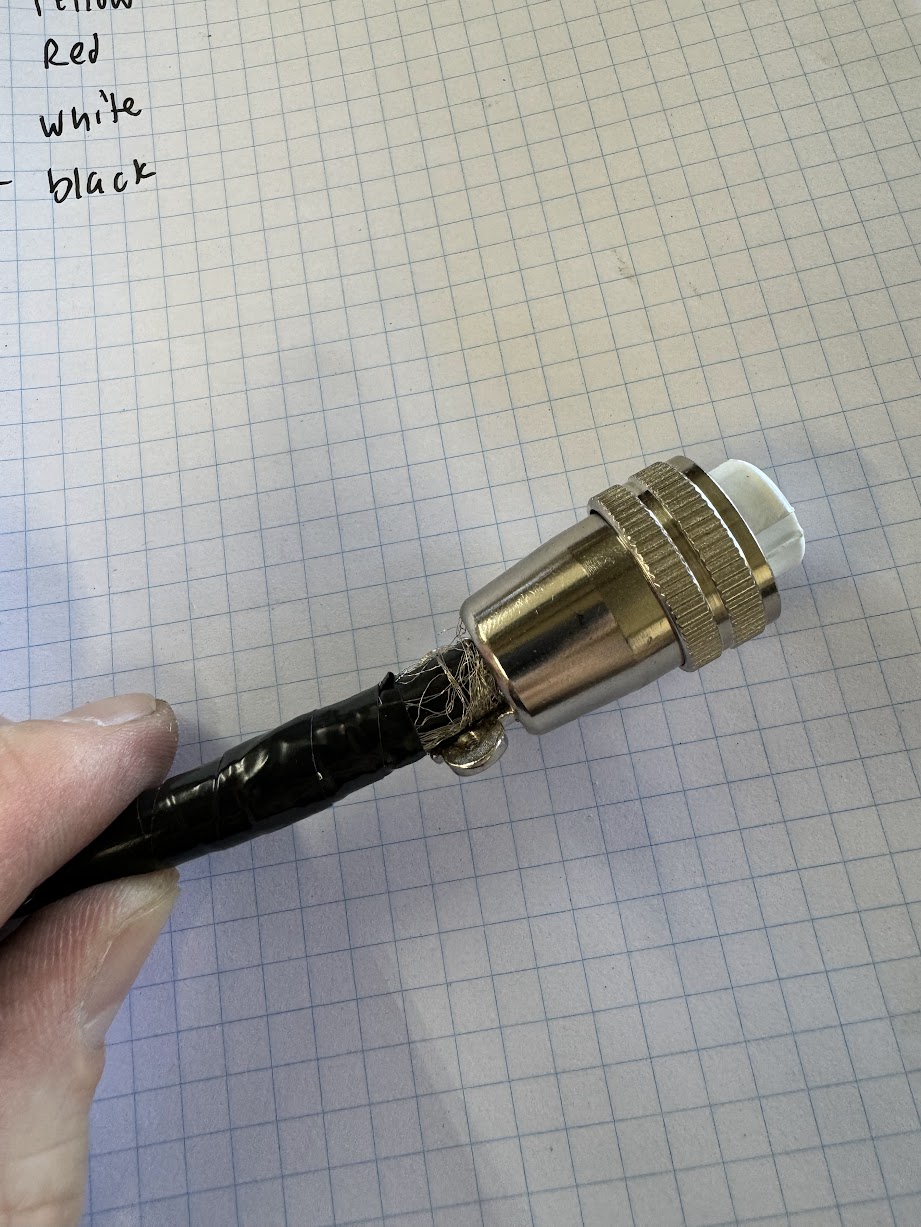
I would suggest buying a premade spindle cable. This was annoying to solder, and I consider myself decent. Need to use a big tip, and lots of flux.
How to ground these cables is pretty controversial. I couldn’t find clear guidance. On the spindle side, I clamped the shielding into the connector.
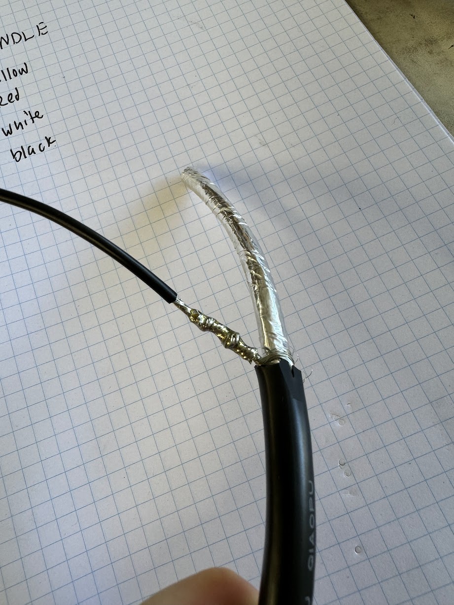
On the VFD side, I soldered another wire on and included in in my ground connector.
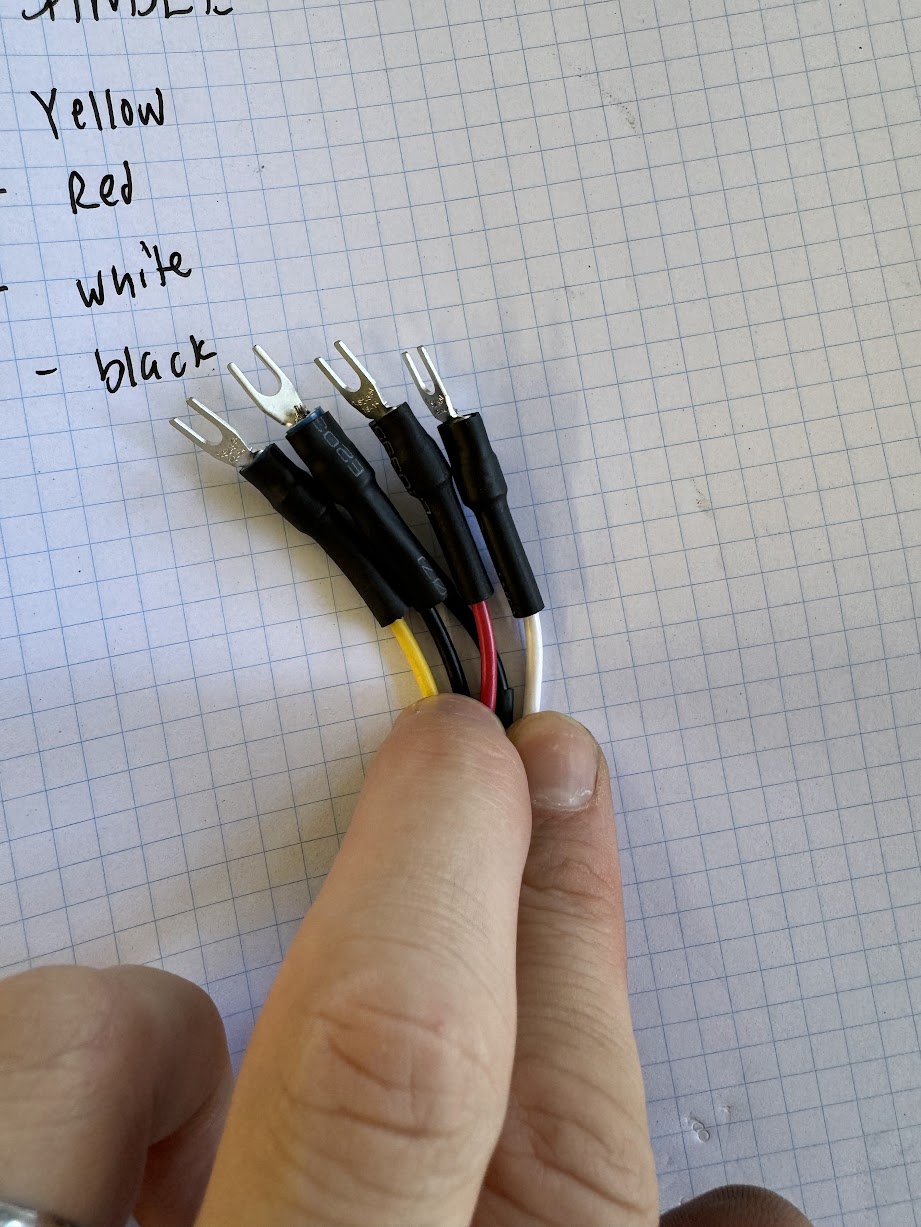
Black is ground for whatever reason I decided.
It is spinning!
50 Hertz × 2 × 60 seconds / 2 poles =~ 3,000 rpm
The instructions online say to run it for 30 minutes at 3k RPM, then increase the speed and run it more. They don’t say by how much or such, so I’ll let it break it some.
So next up is figuring out how to get SKR to control this.
I think I am running the firmware after we enabled PWM laser pin, so I should be able to use that.
I think I can use the fan pin for enabling the spindle. Right now it controls the IOT power supply for the Makita.
I don’t know how to properly setup emergency stop, so figuring that out as well. It seems bad to just turn the VFD off. I also don’t think that is going to stop the spindle immediately
Trying to figure this out now. In the firmware
opt_add SPINDLE_LASER_PWM_PIN PC9
opt_add SPINDLE_LASER_ENA_PIN PB0 // Heater2
PC9 looks like a 3.3v PWM. The VFD needs 5v or 10v PWM.
PB0 looks like source voltage (12/24v).
Hmm, not sure what to do yet. I don’t think there is any 5v PWM and I am not sure what voltage I need to drive the logic on the VFD.
Actually is looking for 0-5v or 10v voltage. I don’t know if it actually needs to be PWM.
Current thought is I can use a relay for enable
and a level shifter for PWM
I’ll come back to this later though. I’ve researched too long
I guess I could set it up and run it manually. I get +1 more button press, but would be able to further test the performance of the spindle and can figure out the details later.
I ran mine manual for a LONG time before I got it running automatic. It’s no worse than clicking the button on the router.
Yeah and in the back of my head - I am realistically going to upgrade to the Jackpot anyways. So do I waste time / money / energy trying to make it work with SKR pro / Marlin anyways?
Yes DO figure out exactly what voltage the logic on the VFD is expecting/outputting.
I did NOT do this and fried a few pins on my mini rambo before I figured it out. I ended up using this one: Amazon.com
For 0 to 10V control, Jackpot needs an add-on module. It’s like $10 on Tindie from Bart, but you would need additional hardware to run that spindle type with Jackpot/FluidNC.
Yup, or the 485 board which solves the isolation concerns too.
Is your vfd set up for RS485? Not all of them are
I haven’t tested it, but supposedly
Even better.
JJ has a working config with RS485 so that should help on the FluidNC side of things too. Need a different module off of Tindie to make that work.
I am following this break in procedure -
https://support.pwncnc.com/kb/article/290-spindle-break-in-procedure/
6000 rpm for 20-30 min - 100hz
9000 rpm for 20-30 min - 150hz
12000 rpm for 20-30 min - 200hz
18000 rpm for 20-30 min - 300hz
24000 rpm for 20-30 min - 400hz (max speed)
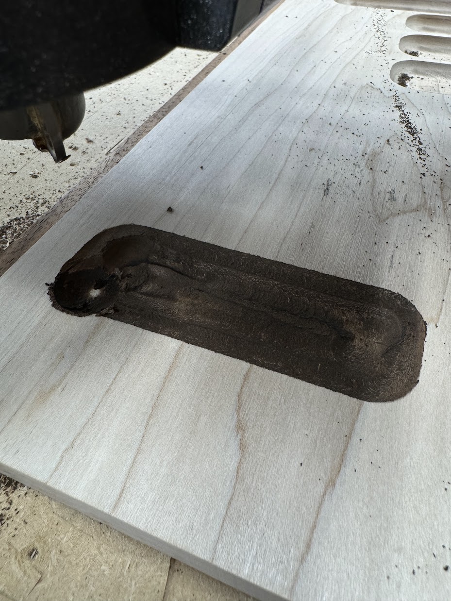
What happened??
I ran it in reverse. Apparently you have a 50/50 shot of getting the correct direction with a spindle.