From the hardware side I recently helped someone else get their laser running. In the latest version of the firmware, pin 45 is defined as the laser and spindle speed control pin. You will find this line in pins_RAMBO.h:
#define SPINDLE_LASER_PWM_PIN 45 // Hardware PWM
And you can find that pin here on the Rambo board in this pic:
The laser is then controlled using the ‘s’ parameter of G1 commands with values in the range of 0 to 255.
Since you have a working setup, you probably already know this, but if you are powering your laser from a separate power supply, that supply and the control board must share a ground connection.
I know that this is an old post but I’m just putting this here for anyone that may run across it in future. I have one of the NEJE lasers as well however when mine arrived the wiring harness although the same as pictured above was originally opposite from the factory!
In other words, from the factory, Green was 12V, Yellow was Ground, Black was PWM and Red was C (Temp). I switched the wires so that the color coding makes sense.
If you don’t switch the wires on the laser plug. You would likely burn out your laser module if you hook it up as shown above.
I also received my Neje 20W laser with the supplied laser cable color coding bass-ackward (left-to-right vs right-to-left); i.e. against convention. I re-ordered the wires to use a more conventional red and black for +POWER and GND, respectively… yellow for PWM, and green for TEMPERATURE/C. While the wires don’t really care what color they are… it might well confuse you if you aren’t sure of what wire is carrying what…
Hi @dkj4linux would you please tell me in your experience which diode laser I could attach to my MPCNC using MKS board and able to cut 5mm acrylic? Thanks
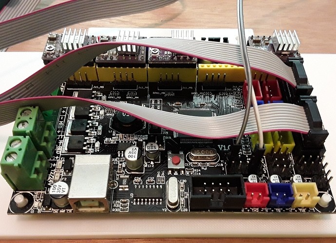
Check out this post (and following) where I put a MKS Gen L v1.0 board on my FoamRipper machine (this was the last Marlin-based laser machine I messed with…)
Since the MKS Gen L v 1.0 is a single-board Mega/RAMPS equivalent, I was able to do the RAMPS “remapped D9 to pin44” mod with my 2.5W Banggood/Eleksmaker and control it with M106/M107 gcodes. It worked well. I’ve since started playing with the 4-wire Neje laser modules (they’re cheaper) as well and they can be controlled the same way as shown here… ignore the Temp/C connection and just use the +12V, GND, and PWM pins. Tap the +12V and GND connection from the board’s power connector (lower left) for the laser’s power and use the remapped PWM pin44 (isolated white wire)… the gray wire is simply a GND connection.
As far as cutting acrylic with your laser, I can’t help too much… I’ve done no acrylic cutting at all. My guess is that a diode laser will be totally ineffective with clear/transparent acrylic… possibly better with some opaque/colored material. Sorry…
You are right, tried this with a 5.5w laser and I can confirm that even with very dark transparent acrylic diode lasers are completely ineffectieve due to the wavelenght they operatie.
Добрый день. Поставил новую прошивку на RAMPS 1/4 marlin и подключил лазер с управлением PWR, 44 пин для управления не работает. Что может быть не так? Измерил напряжение на D9 там оно меняется пока работает программа гравировки. Как сделать управление с 44 PIN? заранее спасибо LT-80W-AA
Hello friends,
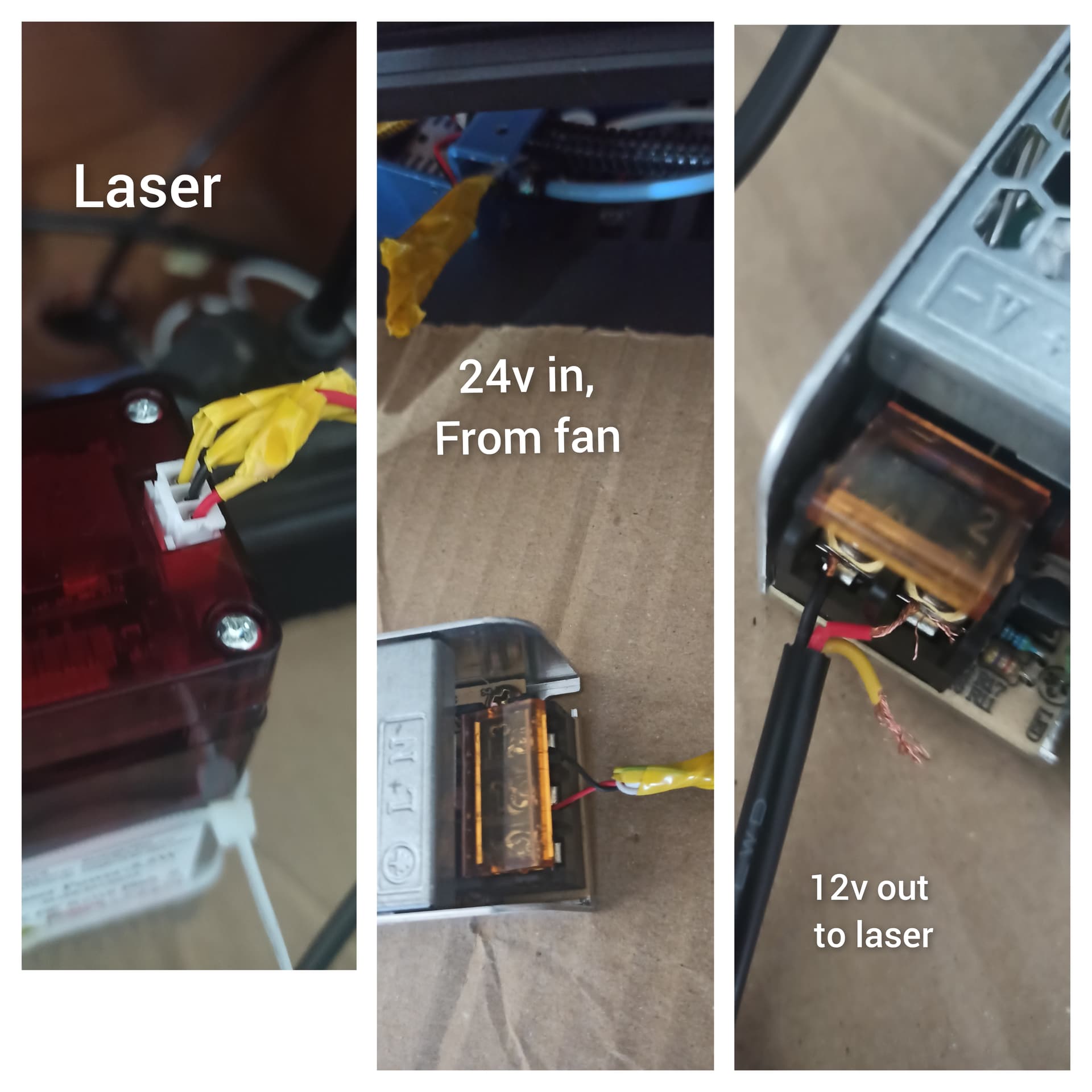
I want to make Engraving Machine from 3d printer. But my knowledge of electrical connection is poor. My laser has 3 pins. +, -, pwm. I took the electricity from the fan and changed it from 24v to 12 volts. (with LED transformer). I couldn’t find a place to make the pwm connection on my laser, it stays disconnected. because the transformer has 2 outputs. Without a pwm connection, the laser does not emit a beam. The laser fan works when there is + - connection. How can I find a solution? İ added connections photos. thanks
What you are trying to do may be difficult or impossible. In order to figure out that connection, we need the following information:
What control board is your 3D printer using? If you don’t know, give us the model of the 3D printer and a picture of the control board.
What laser module are you using? In particular we need to understand what voltage PWM signal it will accept. Usually, the sales page for a laser model will list the PWM requirements.
What firmware are you running on your control board? If you don’t know, usually it is listed on the boot screen.
The third wire, the PWM signal, will connect to the control board, not the power supply. There are a couple of ways of controlling that pin, but it will depend on firmware and the pin available. In an ideal world, you will have a PWM pin available, and be running a version of the firmware where laser support can be enabled (requires reflashing your control board). In a less than ideal world, your laser responds to the PWM signal from a fan pin, and you are running a firmware where you can control the fan pin.
P.S. I have some concerns about how you are powering your laser. If you have a bigger laser module, pulling the power from the fan is problematic. Plus, you will have to enable that pin through g-code.
I still cannot find some critical information. We need to understand what voltage is expected for the PWM. It is very likely that it will accept a 5V PWM signal, but if you have any other information for your laser module, finding the PWM voltage for sure would be really helpful.
So, there are three approaches to getting this laser working:
#1 Use the fan output as the PWM signal - This does not always work, and the engraving results are not very good with this approach. For this to even have a chance of working, you need to use a separate power supply for the laser. The fan pins are almost always ground side switching, so you can use the ground connection of the fan pin and any 5V pin to drive your laser. There are many 5V pins on your control board. If you want to go this route, I can give you further information.
#2 Reworking the firmware to enable laser support and/or drive - In my searching on your control board, it is likely that your board is running some version of Marlin. If you want to go down this pathway, your first step will be configuring a version of Marlin and getting it working with your board. This pathway is the most work, but will produce superior results when engraving.
#3 Control the laser through arbitrary 5V PWM pin and use an M42 g-code to set the pin state directly - The issue with this pathway is that laser cutter authoring tools do not necessarily support it. You may have to postprocess your g-code files, plus it also has the quality issues associated with #1. This approach has a higher chance of working than #1.
You need to pick the approach/pathway you want to take, and I can expand on what needs to be done.
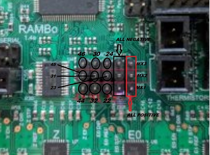
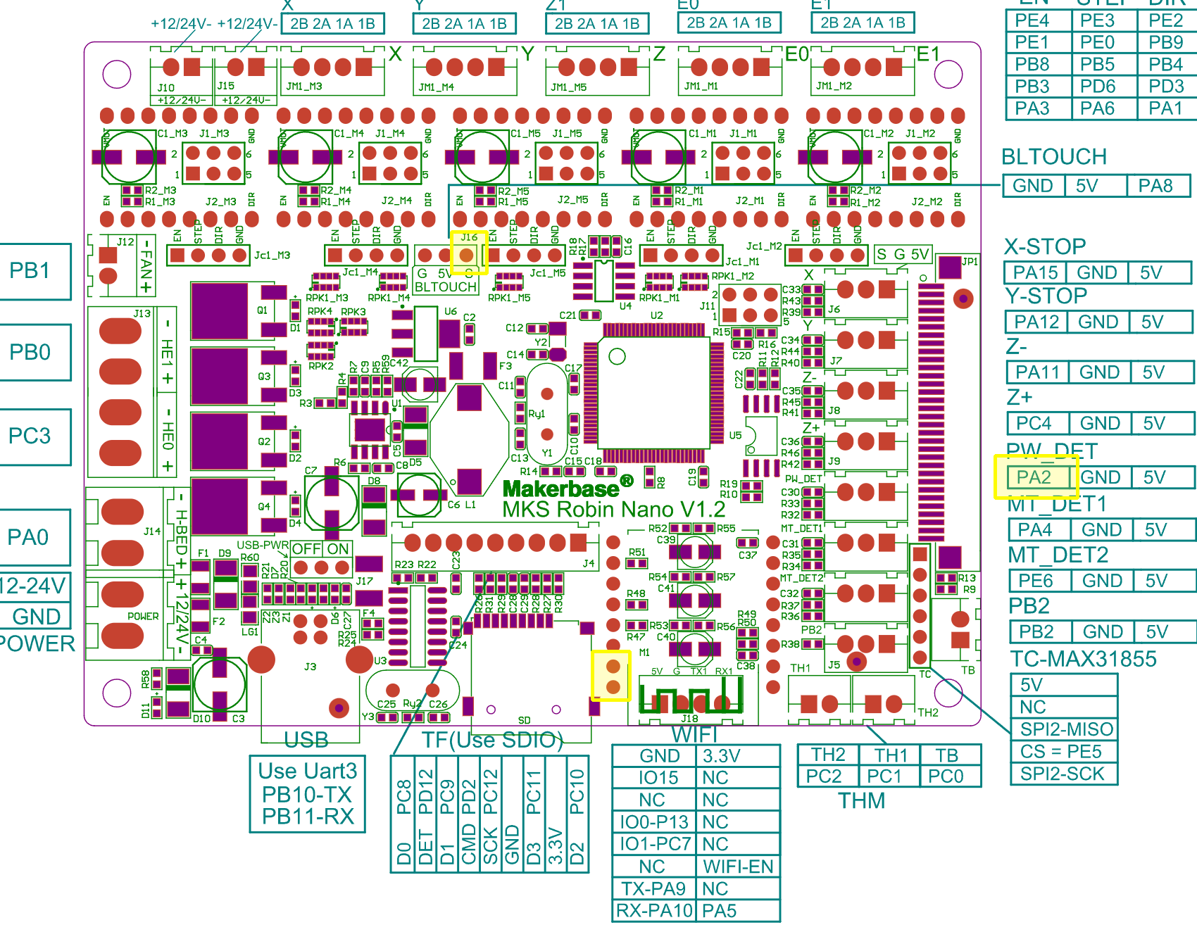
Here is a pinout diagram. I’ve highlighted four possible 5V PWM pins for use for your laser. I don’t know if the hardware or firmware is currently using these pins. If any of them are free, you can connect the yellow wire of your laser to one of these pins. You can then use a M42 g-code to control the pin and your laser.
I would recommend carefully connecting your selected pin to a multi-meter in DC voltage mode, and using M42 to verify the voltage changes with different S values.
This hookup and M42 use is pathway #3 in my last post.
Bltouch pins not using. i m not using this pins. İ can ise this
Is it enough to just solder the yellow wire? to the s pin? and my bltouch g, s, 5v. Something else occurred to me. If I directly connect my laser here, will it work? because my laser also has 3 pins. Maybe I don’t have to use the transformer to step it down from 24 volts to 12.
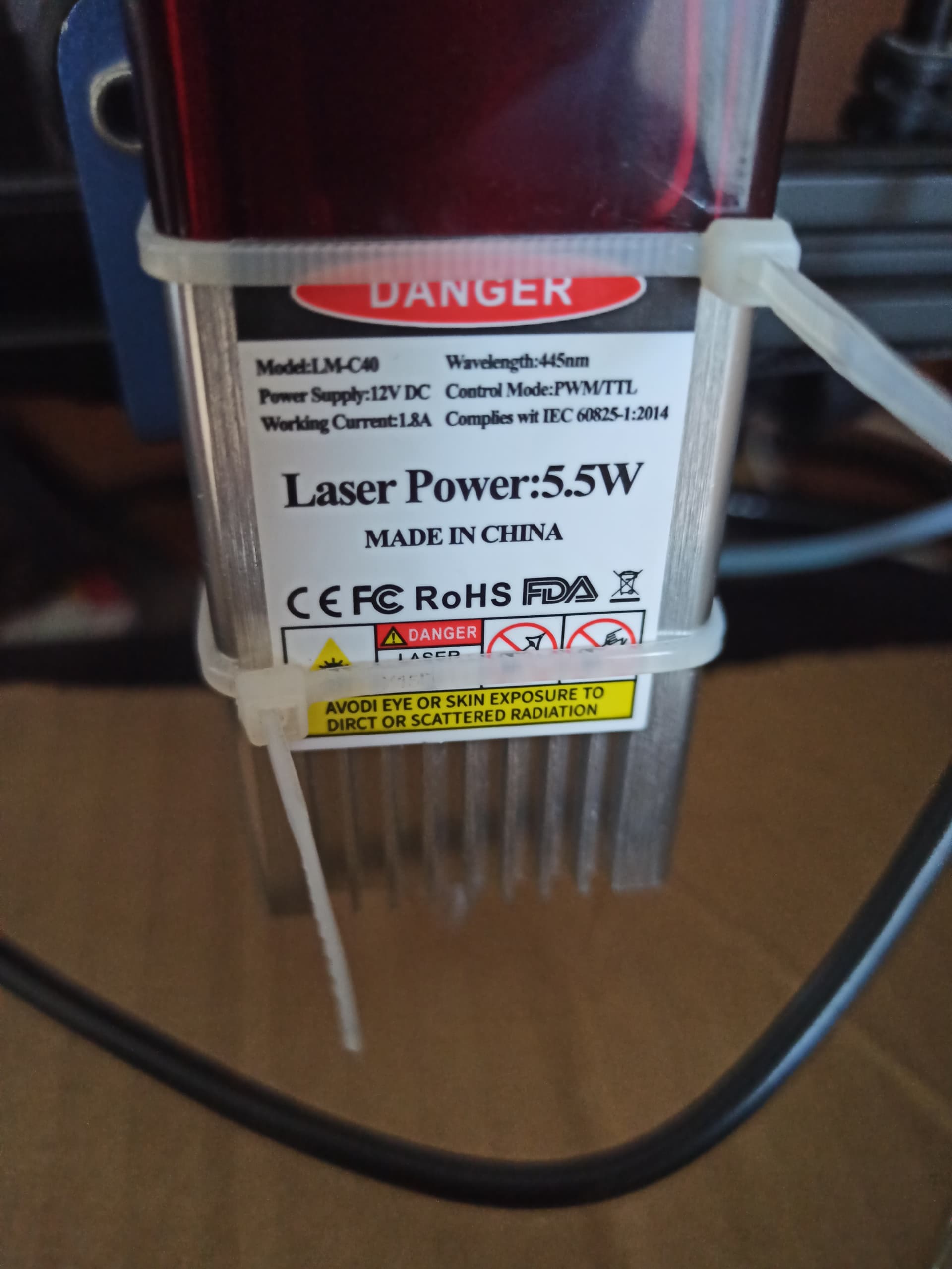
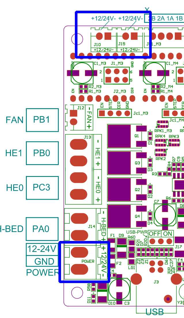
No, you cannot use the BL Touch connection to power your laser. You need to provide the laser with 12V, and 1.8A, and the BL Touch connection is 5V and would not handle 1.8A. You should pull the power for your laser from either where the power comes into the board (lower left of the diagram), or there are a couple of pin pairs provided for this kind of functionality (upper left). Pulling from where the power comes into the board is the preferred/safer method. The two places to connect to power are in the blue boxes in this image.
Personally, I would not solder to the pins. It could work, but the preferred method is to solder on a connector. Any Dupont wire connector will do the job. You can get kits for attaching the connector, but personally I just buy the pre-made wires, and cut and solder them to the end of the wire.
I understood. that there is no need to connect it to the S PIN and after do anything. (I said for electrical connection). I reduced the power from 24 volts to 12 volts thanks to the transformer from fan pin (I am measuring 11.2 volt output). after I will configure laser
I will try and then I will have questions for configuration again :)))
Go buy an automotive 12V lamp, say a 194 bulb, and connect it to your 24V supply. (Don’t touch the lamp when you turn on power.) Now imagine that lamp is your laser module…
Or, you can take our advise and do not power your 12V laser module from 24V!
So what you need is a common ground between your 12V laser and your 24V control board. You can connect the grounds (negative power lines) together without problems. You can either use a buck-boost step down module on the 24V power (capable of 2A or better) or a separate 12V supply.
This takes care of power.
You need the ground to be common so that the laser can “read” the PWM signal. This can be the servo pin from the BLTouch port or another PWM pin. Probably your laser will be fine with 5V or 3.3V PWM/TTL. Connecting the Signal pin to the BLTouch port or a servo port handles the control signal.
I may be missing something, but he said he is using power from the control board to power the laser, so they should be sharing a ground without adding any additional wiring. I am concerned that 1) he is attempting to pull power from the fan pins, and 2) the use of the word “transformer.” I’m assuming he is using some sort of switched power converter, but IDK.
I am using LED transformer to step 24 volts down to 12 volts. Unfortunately, I couldn’t find 12 volts directly. then I connect 12v (actually I measure the output 11.2 volts) to the laser + -. but as I said, the pwm cable was idle at the last stage. I think I will solve the problem with bltouch (about pwm cable).
Is there a wrong or reverse situation like this now? need change?

