I have it separately wired at the moment, I was just wondering if the VMOT could supply 2.5A
I finally have a no error reboot!! However I still can’t move the motors with Lightburn, but I can get them to home (but the wrong direction).
Tweak,tweak,tweak.
and it’s homing the correct direction and reacting to the switches. I thinnk I can figure it out from here. I will post my yaml when im happy with it.
Thanks guys!!
Mike B
So was it just the yaml? Or power?
I think it might have been power on a couple attempts, but mainly it was the yaml.
I’m just getting back to it this morning and will be reviewing MakeerJim’s file for the individual stepper settings, but I do have movement with FluidTerm.
1 Like
@mbamberg @RockinRiley @MakerJim
Have any of you successfully used a roller rotary with Fluidnc and Lightburn?
I’ve watched lots of videos and read lots of articles and posts, but I can’t get mine to rotate the correct number of mm.
I read that Lightburn uses angles and grbl should convert it to steps, so I’m wondering if Fluidnc doesn’t do that correctly.
1 Like
@Fabien built one and got it to work. I am working on building the same one but other projects and life have gotten in the way of finishing that.
1 Like
Check out @dkj4linux posts. He is one of the prominent laser people here. I have barely used my laser! Also lightburn has a forum about as nice as here.
I have been following @dkj4linux for a long time now. It started when I built my first needle cutter and now his laser posts. He doesn’t use FluidNC though.
I have posted on the Lightburn forum also. Nobody has replied there either.
1 Like
I haven’t used that combo.
I have used LightBurn with a rotary axis at the local makerspace. They have a 60W CO2 laser with a Ruida controller. To calibrate it, we figured out how many steps to spin it 5 times back to a marked starting point and then did the math.
If I recall correctly, the way you set up LightBurn is you tell it the number of steps to make a full revolution of the A axis roller.
From LightBurn, you can hit “test” and it will spin the rotary axis one revolution and then go back. Makes it fairly easy to be sure you’ve got things set correctly.
Each Job requires you tell LightBurn the diameter or circumference of the stock you’re engraving.
1 Like
Thanks for the reply @MakerJim
It asks for mm per rotation, not steps per rotation in the new version. I tried different (mm per rotation) to get it to do one full rotation, but it never did.
All the videos either skip the mm per rotation setting, or they say just try different numbers until it works. I never found one that explained how and why.
I pressed the Test button once, and it made the X axis move erratically, and then the rotary turned a little. I was afraid to try it again.
So there must be a steps/mm somewhere. I guess that would be based on the rollers. Either that or there must be a steps/rotation somewhere.
mm per rotation then must be the circumference of the object being worked, and would be different for different objects. A piece of 50mm tube would be different from a piece of 75mm for example. Since pi is an irrational number you would want to keep the error to a minimum and not just keep rolling, so roll both directions with minimal crossing the seam line, I guess.
If it’s a chuck, then rotations are fixed, and you want to know a distance so that the aspect ratio doesn’t get skewed. Also if something requires covering an area, you can cover it with appropriate spacing. If you are movimg around the circumference, and you want to know the travel speed, then yoi still need to mnke the distance per rotation.
Either system works if you are basing it around a tool size, like an endmill or a laser spot, and allows you to configure resolution, aspect and tool speed.
@SupraGuy
It’s been driving me crazy. The Lightburn Docs say the mm per rotation is independent of the object being rotated. Once you have it set you don’t have to change it again, you only need to enter the diameter of the object you are engraving. I tried several different numbers and it never made a full rotation.
My rollers are 19.82mm in diameter.
19.82mm X 3.14 = 62.2348mm
I don’t understand why 62.2348mm doesn’t work in the settings.
I am taking a break from it for now. Maybe someone else will attempt it and figure out how to get it to work with the new board.
There must also be a steps/mm somewhere. It will depend on the motor, microstepping setup, and whatever is driving the rollers.
Simplest assumption would be that it js set to 100 steps/mm, as most V1 systems would be.
If your rollers are directly connected to the stepper motors, so that one turn of the stepper = 1 turn of the roller, then 1 rotation of the roller would be 32mm according to FluidNC.
If there is a drive system, then it would vary according to the ratio of the drive. (Say a 16T pulley on the motor and a 20T pulley on the roller, then it would be 40mm (32 × 20 ÷ 16) substitute whatever drive system is in place.
I think your calculated value would work if the steps/mm worked. Since it obviously does not, you need to either fix the steps/mm or work out a convincing lie for the mm/revolution.
So some details about the rotary axis would help us figure out the appropriate value. It would also help visualize what’s happening and do some basic sanity check if we knew if it was moving too far, or not far enough.
Steps / mm should be set for the axis in the config.yaml for a Jackpot.
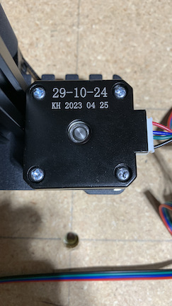
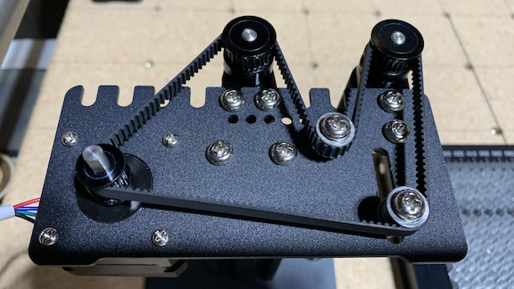
We need details of the rotary axis. Can we get a picture or two?
@SupraGuy @MakerJim
The config.yaml for FluidNC has y: steps_per_mm: 50.000.
The motor has a 16T gear and the rollers have 25T gears.
It does not move far enough. I tried 60 mm per rotation and 923mm per rotation. It moved the same amount for both (130mm).
Okay, 16T is a “distance” on tooth center of 32mm and 25T is 50mm, so the rollers turn slower than the motor, at a ratio of 16:25
1 full rotation of the motor is 200steps/revolution × 16microsteps/step = 3200 microsteps.
1 full rotation of the rollers is 3200 microsteps ÷ 50 × 32 = 2048.
At a nominal 50 steps/mm, 1 full revolution of the rollers is 40.96mm
With the actual circumference of the rollers, actual steps/mm is 2048 microsteps/revolution ÷ 62.2348mm/revolution = 32.9076336712 microsteps/mm
I would probably want to set the correct steps/mm myself. (I don’t think it needs the precision straight from the calculator.)
So you can either define 1 revolution as 40.96mm at 50 steps/mm or as 62.2348mm at 32.9076 steps/mm.
1 Like
Thank you @SupraGuy. I will give that a try and let you know how it turns out.
I tried 40.96mm per rotation, but the motor gear only turned about half way around.
The rotary test button makes the X axis go forward and backward then the rotary goes forward and backward.

Also, the stepper motor on the rotary is a pancake I think. It gets really hot. I reduced the run_amps to .33 and the hold_amps to .2. It is still getting really hot.