II have been reading a bunch of threads where users are experiencing differences in X and Y cut lengths, or there are differences in size between inside (hole) cuts and outside (part) cuts with the same specified dimension.
I’ve compiled suggestions from several different threads into a single list for calibrating my own machine (LR3), with a goal of minimizing those differences and having as accurate a machine as possible.
I want to run this list by the Forum for a sanity check to make sure that I’m not missing anything. Hopefully this can also be a resource for others wanting to fully calibrate their machine.
Comments and feedback are appreciated.
BTW, I’m running Marlin on an SKR v1.2 Pro controller. The process may vary slightly for Jackpot/FluidNC machines.
Prerequisite: Adjust belt tension, ensure core bearings are contacting gantry rails (no core looseness)
Step 1: Square the machine
Home the X and Y axis
Move the machine in a rectangular pattern (as large as possible)
Use a V-bit to create marks on painters tape at each corner of the rectangle (lower Z until the V-bit just touches the tape)
Measure the diagonals of the rectangle with a steel tape and compare for different lengths
Adjust the Y endstops as necessary (my endstops have threaded adjustment screws). If no adjustment screws, use M666 Y(n) to compensate for Y offset
Repeat above steps until the diagonals are within +/- 0.5 mm (pretty much the measurement granularity using a steel tape measure)
Save settings with M500
Step 2: Level the gantry
Home Z axis
Measure the distance between the lower gantry rail and the spoil board at both XMin and XMax (I have some hole gauges that are perfect for this)
Adjust one Z endstop to get the difference between the measurements as close as possible (repeat previous 2 steps as required)
Home Z, then probe using the Touch Probe (G38.2 Z0) to set Z=0 at XMin (G92 Z0.5).
Move the core to XMax and repeat the probe (G38.2 Z-10), but do not use the G92 command
Read the Z position on the display. This will show the offset difference.
Use M666 Z(n) to compensate for a Z Offset between XMin and XMax
Re-home Z and repeat measurements/adjustments to ensure the offset is as low as possible (< +/- 0.2mm).
Save settings with M500
Step 3: Tram the router
Attach Ryans’s printed Tramming Tool to the router collet
Move the tool so that the pointer is pointing toward YMax.
Move the Z axis so the tool is almost touching the spoil board.
Rotate the tool 360 degrees, making note of where the pointer is closer and further away from the spoil board
Remove the router from the mount and place a few layers of painters tape on the bottom mount opposite the lowest point (or on the top mount in the location of the highest point)
Reinstall the router and retest
Repeat until the tool can rotate fully with minimal variation in distance from the spoil board
Step 4: Measure belt spacing (Reportedly some belts from V1E have very minor errors in tooth spacing, resulting in slight errors over long distances.)
Using a V-Bit, make marks in painters tape at YMin and YMax.
Note the Y position at each location (ie. YMin = 0, YMax = 2250mm)
Measure the actual distance between the marks using a steel tape
If difference is >0.5mm, it may be necessary to change the steps/mm for that axis using M92
To calculate required steps/mm: New Steps/mm = (Old Steps/mm (default 100) * Expected Length)/Measured Length
For example, YMax = 2250, measured length = 2247. (n) = 100*2250/2247 = 100.1335
Set new steps/mm using M92 Y(n)
Retest to confirm correct measured distance
Save settings using M500
Repeat test/adjustment for X axis if required
As per @Dreyfus and @CesarH , recheck square if steps are modified (although I am yet to be convinced it is necessary)
Step 5: Perform test cuts
Using appropriate feeds and speeds for the test material (MDF or plywood), create two square cuts of 100mm per side in EstlCAM (one as a hole, one as a part) using Climb Milling. Use a Finishing Pass of approximately 10% of bit diameter. The squares should be oriented such that the edges are parallel to the X and Y axis
Create a second pair of identical cuts, this time using Conventional Milling.
Perform the cuts on a test piece of MDF or Plywood (thinner material and a single cut preferred - use holding tabs).
Measure the distance of both the hole and part cuts along both the X and Y axis.
Distances should be identical for all measured lengths
If the hole and part measurements are different, you may need to adjust the Tool Diameter in EstlCAM to compensate for the cutting width of the bit varying from the nominal width (for example 1/8" bit may be cutting at 3.120mm instead of the expected 3.175mm)
If there is a difference between Climb and Conventional cuts, that may indicate excessive tool flex (reduce cutting depth or decrease stick-out) or looseness in the core bearings.
Please let me know if I have missed anything, or have made any mistakes in the above procedure.
I’ll have to think about that. As long as both belts are the same step value, the diagonals shouldn’t change (overall length would, but not the difference between the two). Or maybe I’m wrong (definitely not the first time)
But aren’t the Y axis both moving the same (different) distance, so while the edges of the rectangle are longer (or shorter), the angles of the rectangle should still be the same, no?
I don’t think that is an option in Marlin. You can set X, Y and Z differently, but both Y axis (and both Z axis) are set the same from a single parameter.
Plus if the belts are from the same lot (usually cut from a single length), then there would be no reason to set them differently.
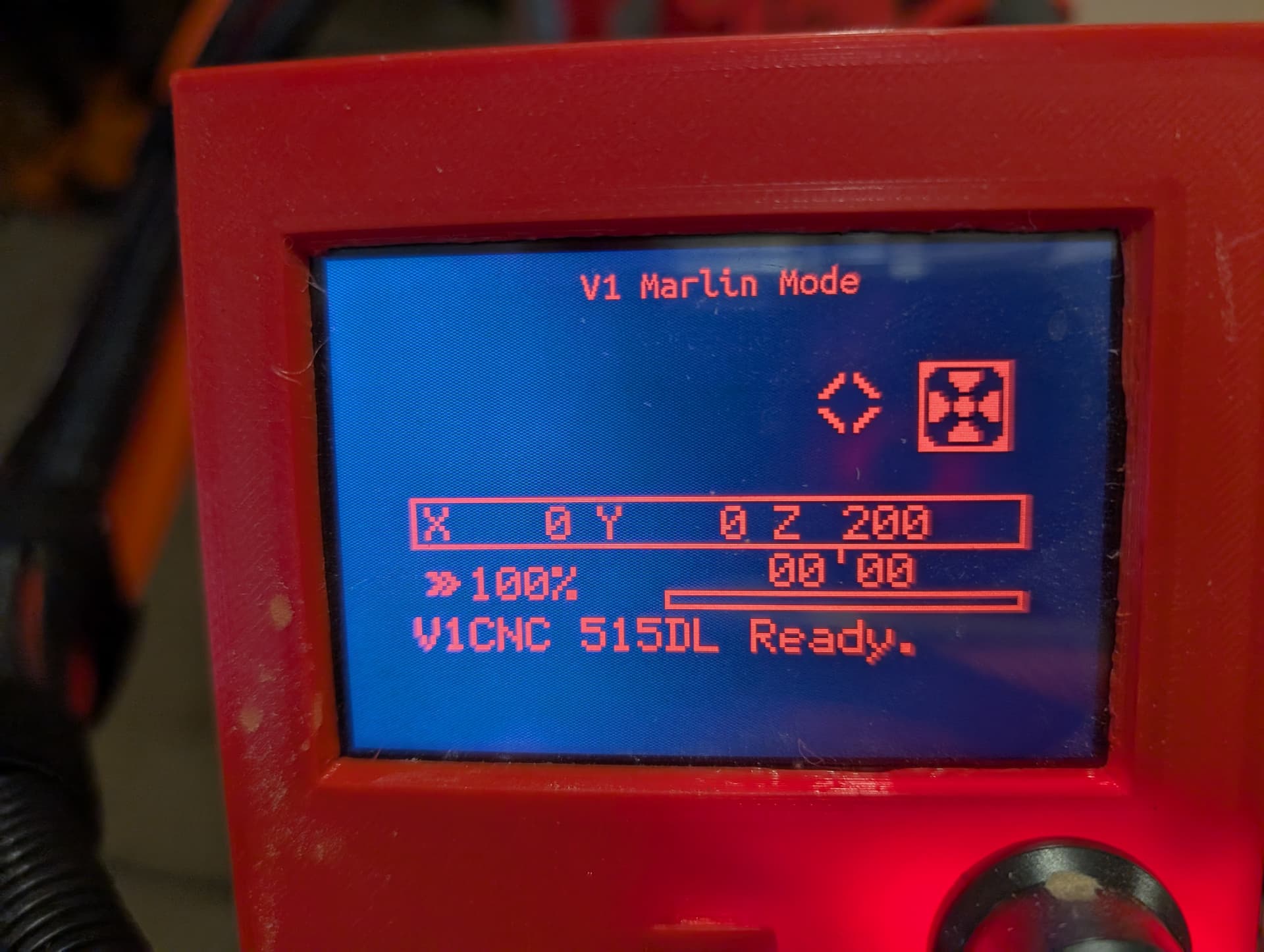
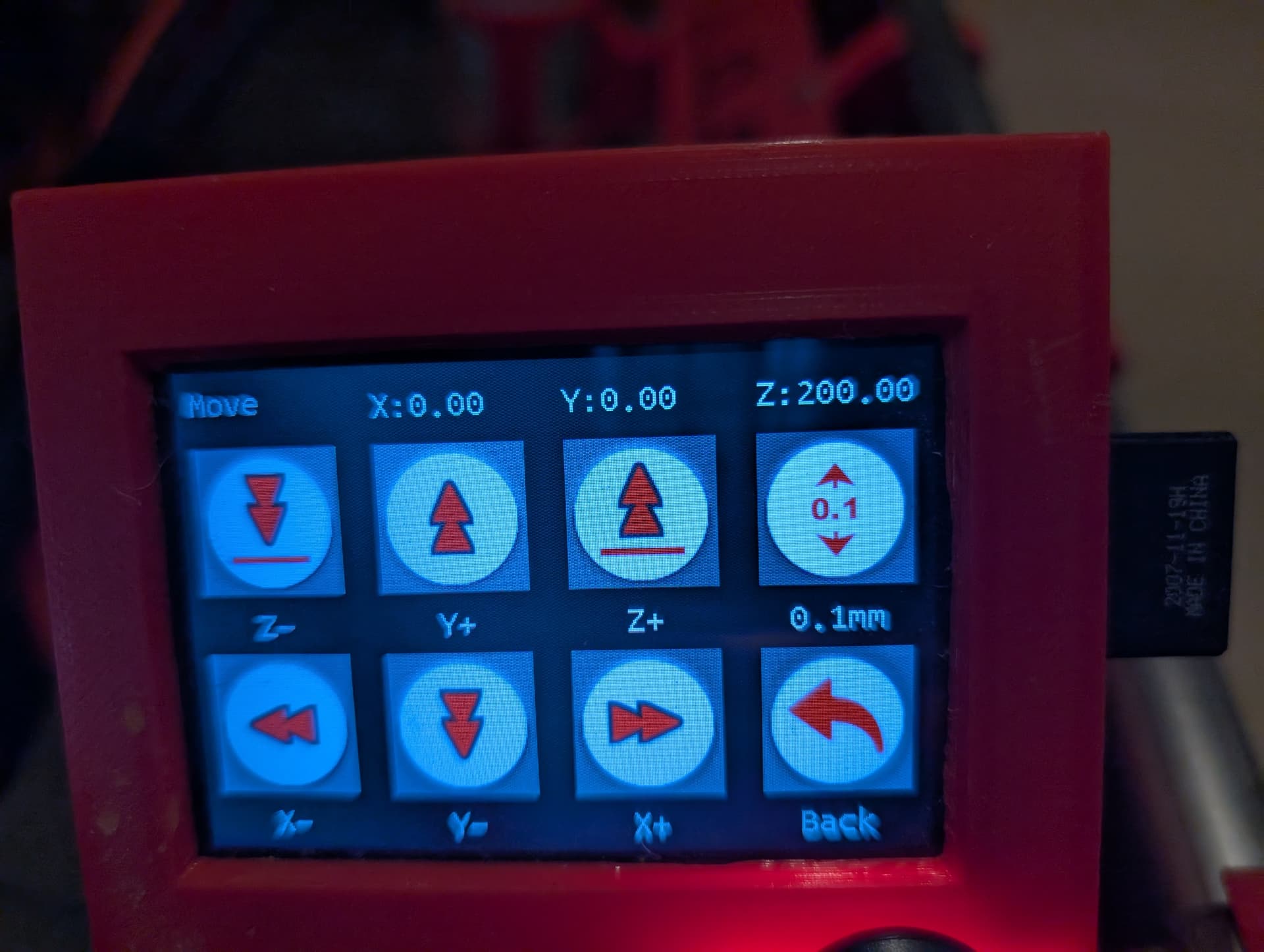
On the SKR, the display will show the X, Y & Z positions. After setting Z=0 at XMin, and then probing again at ZMax (without re-setting Z=(n)), the display should read a value close to (but seldom equal to) 0
These pictures show the position after Homing all three axis, but before probing (Z=200)
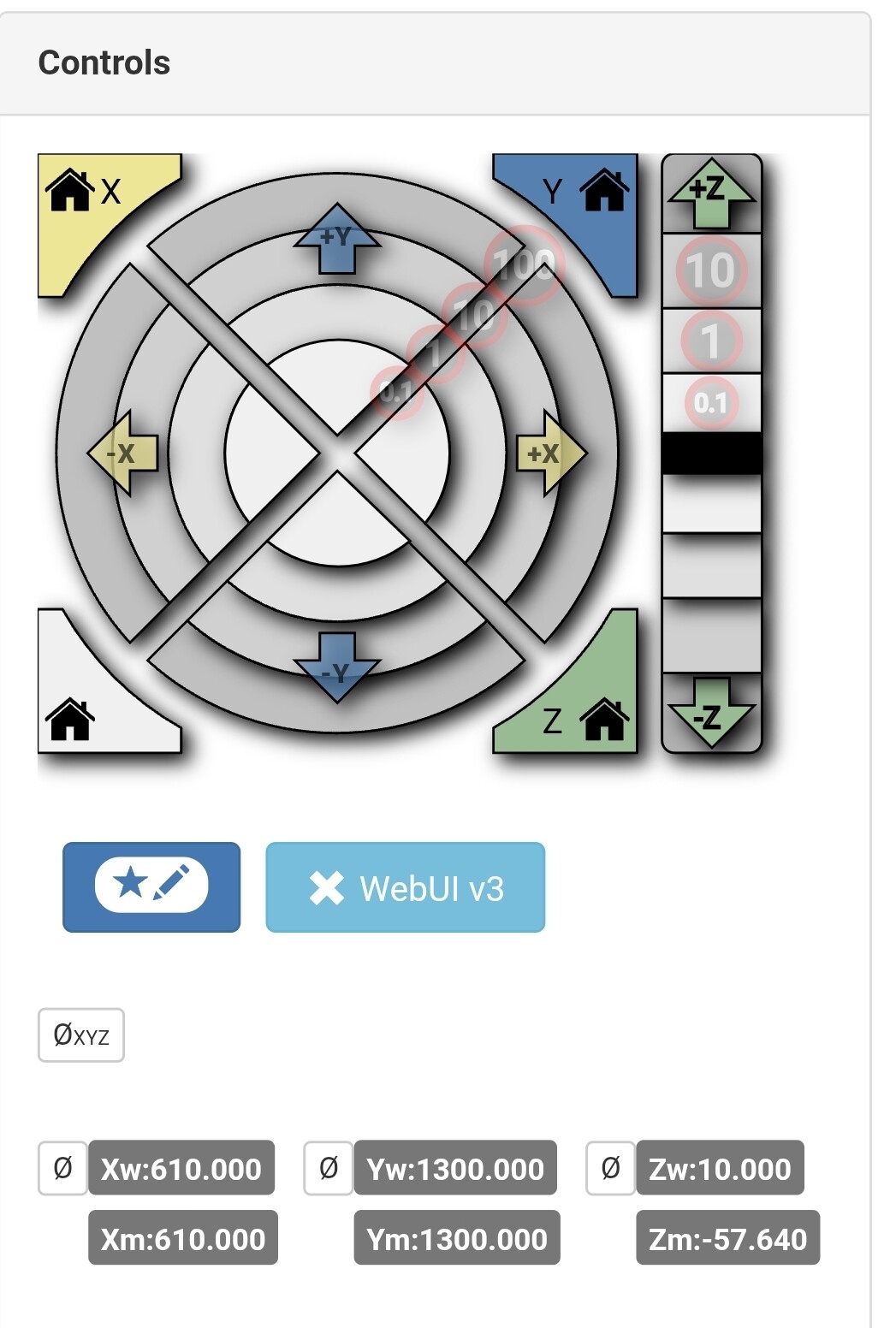
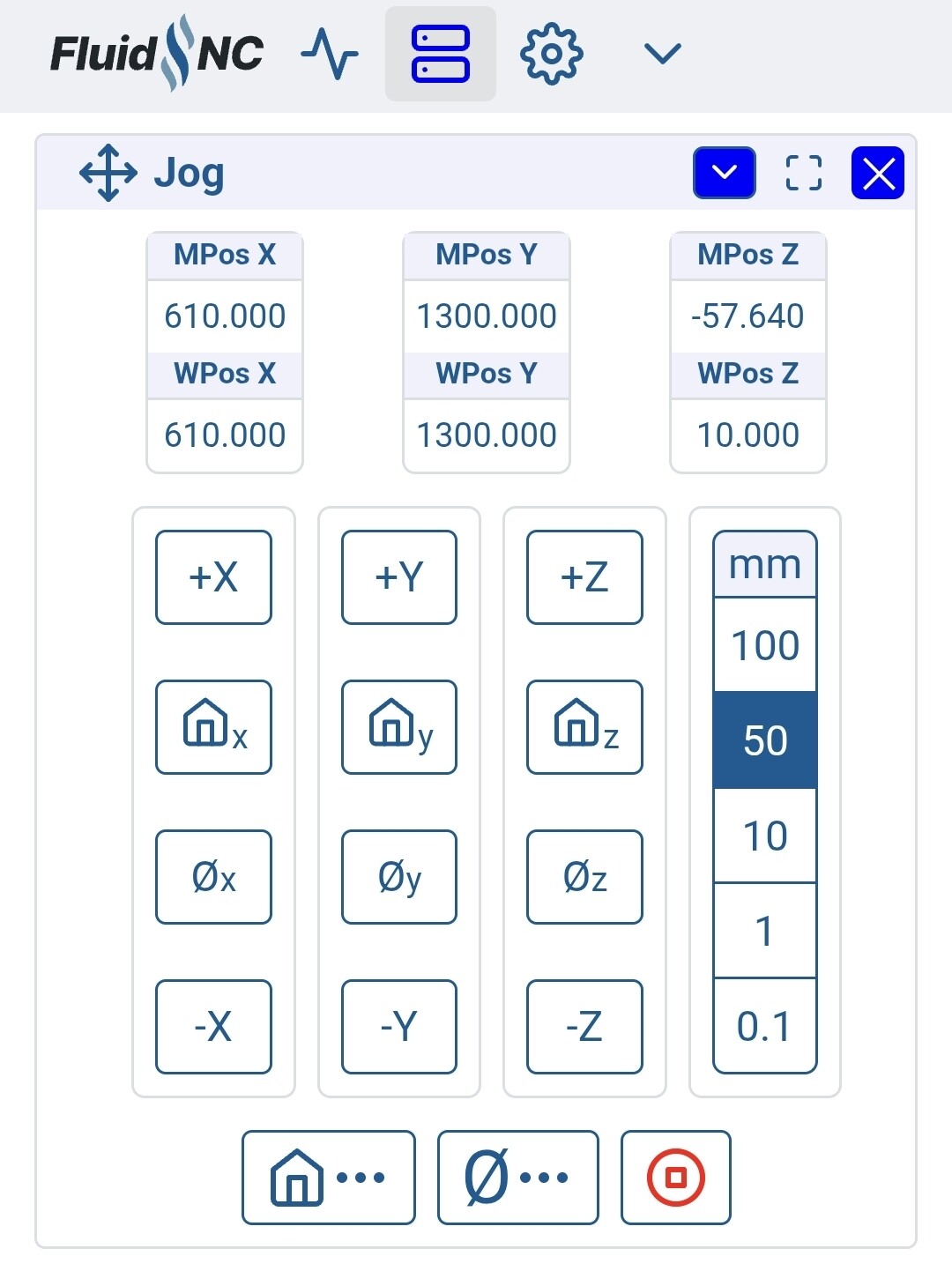
I’ve done this a bunch of times with the Jackpot but I’m blanking a bit. I think you just want to look at the Z position in the working coordinates. I can check later.
Well, for Z leveling with FluidNC (and really anything), you could use either working or machine coordinates. I typically use machine coordinates. If you used working coordinates, depending on how you probed, it could zero those.
The instructions above use working coordinates. So, you probe and zero Z at X min, and then measure at X max to get the difference without re-zeroing. I typically probe in each spot 3 times to take an average so that process doesn’t quite work.
I’m hesitant to say this but I have some automated ways of doing this for FluidNC but they’re half baked. I had a gcode script to do the whole thing and also an extension. I should revisit. It’s one of those things you do so infrequently and it’s not that difficult to do manually that I’m not sure how much value they have.
Is this about adjusting belt tension? Or moving whole belt-holding block? My difference in diagonals is 7mm and documentation says to minimise it before changing M666 value.
The purpose of adjusting the Y stops is to.square the machine, such thst the X axis is as close to 90° from the Y axis as possible. By changing the start points on either end of the X axis we can ensure that cuts made on the X axis are perpendicular to cuts along the Y axis.
The Y axis follows the Y rail, but the X axis follows the Y endstops on either side. If these are not square to the Y rail, then they need adjustment.
@SupraGuy nailed the answer. By moving the endstop, you are in effect moving one end of the X axis (gantry) in order to make it perpendicular to the Y axis.
In this case it makes sense to reposition one of the Y endstops, rather than try to compensate for such a large difference using the offset.
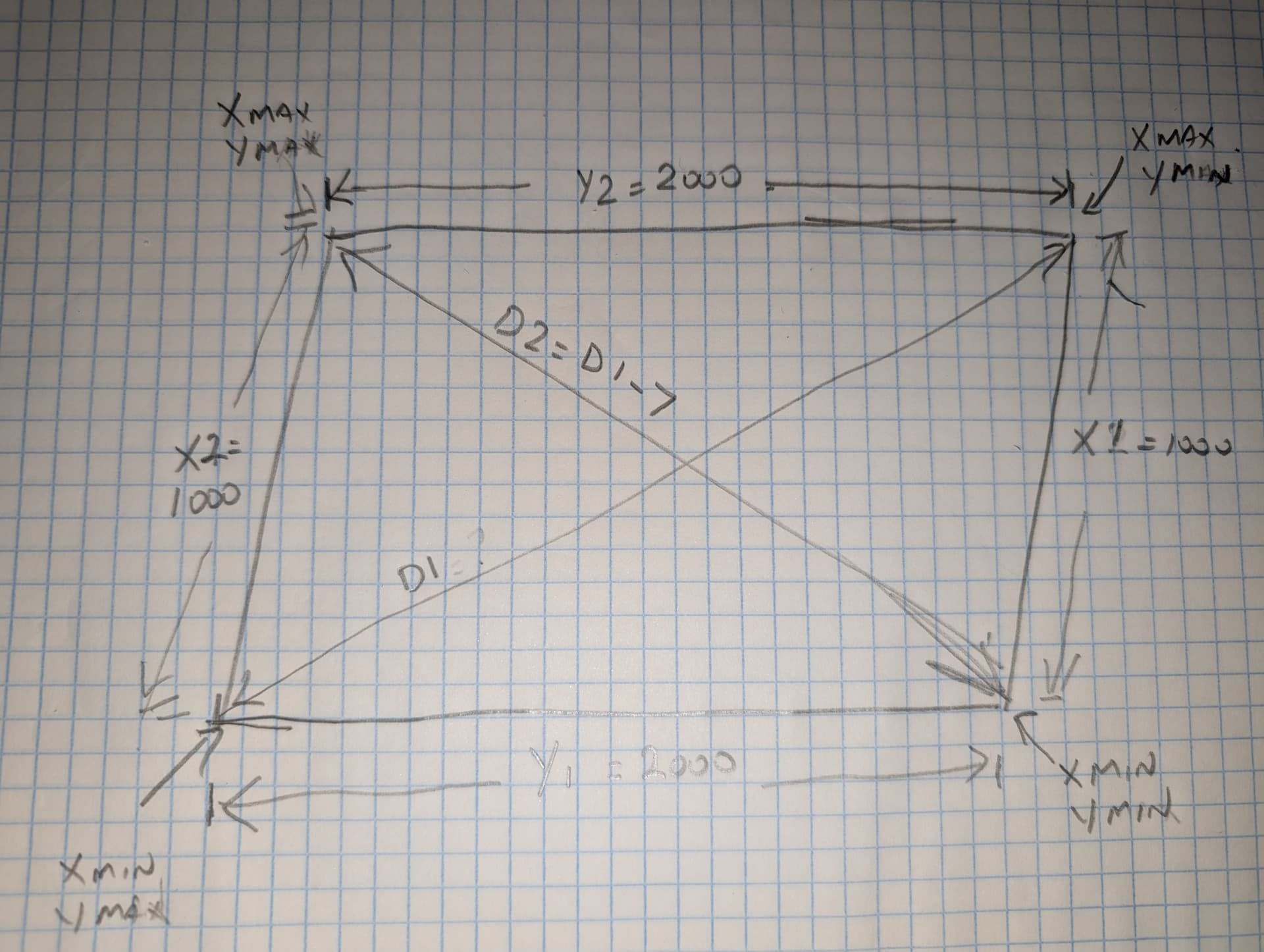
In the drawing, the endstop at XMax YMin is too far to the right (or the endstop at XMin YMin is too far to the left) and the result is that D1 is 7mm longer than D2.
By repositioning one of the endstops (XMax to the left or XMin to the right), you are bringing the angle closer to 90 degrees, which will result in D1 being closer in length to D2.
If the difference between D1 and D2 is only a couple of mm, then the M666 method is appropriate, as it is fairly difficult to make such fine adjustments by repositioning the endstop hold down screws (which is why I used an adjustment screw on the edges of my endstops).
BTW, you don’t want to increase or decrease belt tension when you do this, so you may need to go back and check that after moving the endstops
My whole system is a heavily modified LR3, so it probably won’t work for you. But I think that the stock LR4 endstops come with a hole that you can insert a threaded M3 screw. If not, you may be able to modify it in Fusion or some other CAD program.