Hi everyone,
First, I would just like to thank Ryan for the amazing work he has done making and designing this machine!
I actually printed and built my machine around 2 years ago, but for a variety of reasons I never got around to getting it really going partly living in a townhouse at the time. Now however I have space and am keen to get it up and running properly.
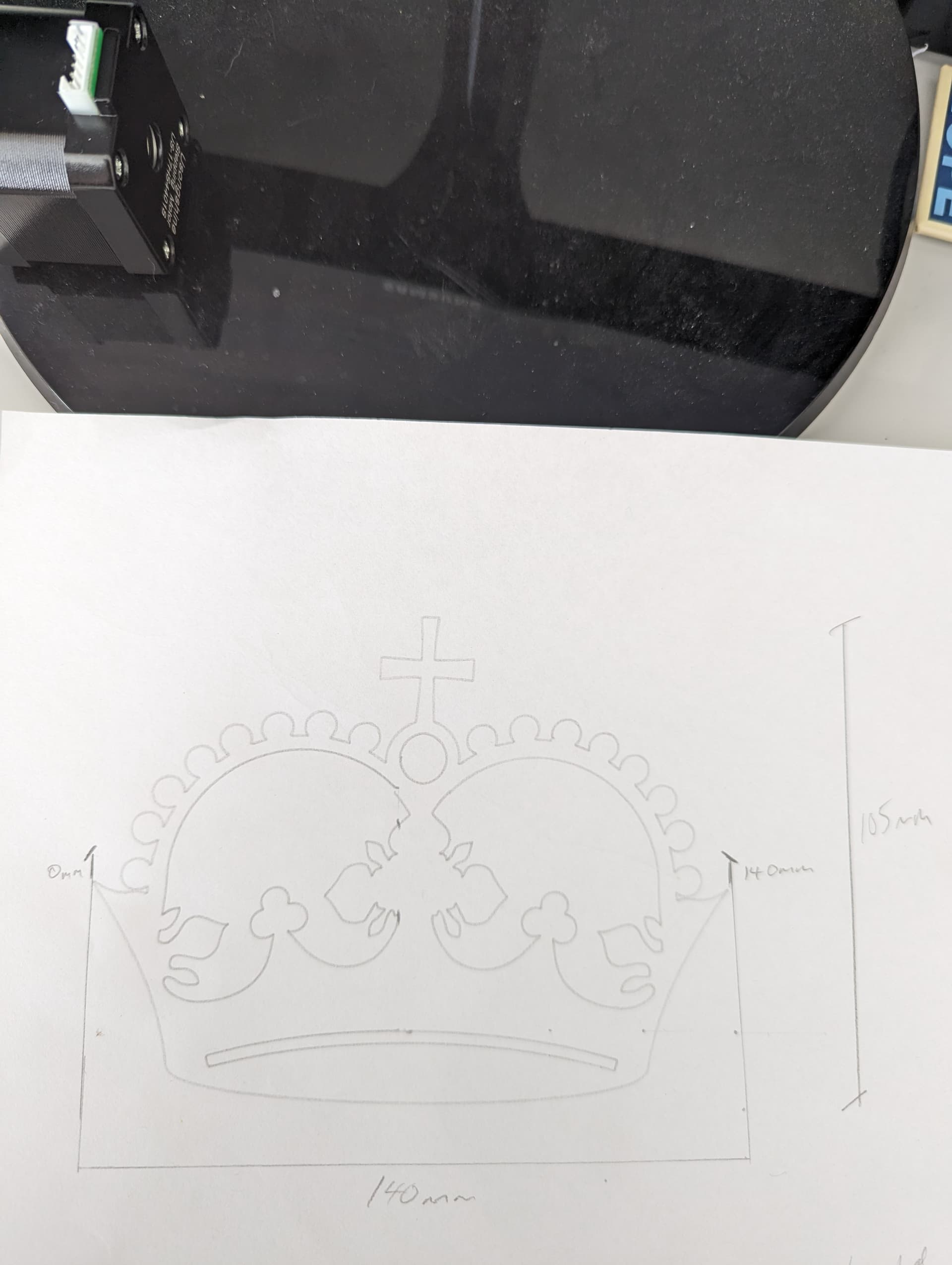
Long story short I did the crown test and it was set for 150w x 112.5h but it is coming out at 140w x 105h as shown in picture.
I bought my belts and pulleys off Ryan, and my motors are USONGSHINE 17HS4401S 1.8d, with CNCjs used to send the file
This is the code
CNCjs 1.9.22 [Grbl]
Connected to COM4 with a baud rate of 115200
Grbl 1.1h [‘$’ for help]
client> $$
$0=10 (Step pulse time, microseconds)
$1=25 (Step idle delay, milliseconds)
$2=0 (Step pulse invert, mask)
$3=0 (Step direction invert, mask)
$4=0 (Invert step enable pin, boolean)
$5=0 (Invert limit pins, boolean)
$6=0 (Invert probe pin, boolean)
$10=1 (Status report options, mask)
$11=0.010 (Junction deviation, millimeters)
$12=0.002 (Arc tolerance, millimeters)
$13=0 (Report in inches, boolean)
$20=0 (Soft limits enable, boolean)
$21=0 (Hard limits enable, boolean)
$22=0 (Homing cycle enable, boolean)
$23=0 (Homing direction invert, mask)
$24=25.000 (Homing locate feed rate, mm/min)
$25=500.000 (Homing search seek rate, mm/min)
$26=250 (Homing switch debounce delay, milliseconds)
$27=1.000 (Homing switch pull-off distance, millimeters)
$30=1000 (Maximum spindle speed, RPM)
$31=0 (Minimum spindle speed, RPM)
$32=0 (Laser-mode enable, boolean)
$100=200.000 (X-axis travel resolution, step/mm)
$101=200.000 (Y-axis travel resolution, step/mm)
$102=200.000 (Z-axis travel resolution, step/mm)
$110=500.000 (X-axis maximum rate, mm/min)
$111=500.000 (Y-axis maximum rate, mm/min)
$112=500.000 (Z-axis maximum rate, mm/min)
$120=1.000 (X-axis acceleration, mm/sec^2)
$121=1.000 (Y-axis acceleration, mm/sec^2)
$122=1.000 (Z-axis acceleration, mm/sec^2)
$130=200.000 (X-axis maximum travel, millimeters)
$131=200.000 (Y-axis maximum travel, millimeters)
$132=200.000 (Z-axis maximum travel, millimeters)
ok
Appreciate any assistance!
On a side note, my motors sound musical at times when running, is this right or do I need to adjust something? I have a recording of the motors running but it is a M4A file which i can’t upload.
Cheers