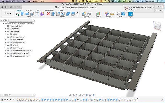
CNC-cut table for LowRider v3 (parameterized, for cutting full sheets+)

For two more parametric CNC-cut tables for LowRider v3 — click here: Two more parametric CNC-cut tables for LowRider v3 — 24"X48" and 48"x24" versions, at 3.625” tall

1 Like

I think i broke your f360 file lol. Was trying to see if a 2meters wide torsion box was posible

Hi Doug,

I didn’t have time to read your post until now. I´m not sure about the X-gantry on the 48" axis.

It seems like this is not recommended?

Thank you for the steps. I don’t have a router yet so I think I’ll build a table that can cut the struts in the Y-axis

If you wanted to build a wide X with a short Y, because of planning a long Y later… it’s not a bad way to go. But unless you have a reason like that, putting the X gantry on the shorter axis has a little better rigidity. I made table versions going either way:

For two more parametric CNC-cut tables for LowRider v3 — click here: Two more parametric CNC-cut tables for LowRider v3 — 24"X48" and 48"x24" versions, at 3.625” tall

1 Like

Hi Doug,

I have my tubes cut at 1400 mm and a wide X and a short Y is what I can make room for right now.

I don’t have Fusion 360 yet. How much material would a wide X and a short Y take?

I am not sure if the belt moving towards me (wide X) is easier to use?

If you begin with the 8" tall version I posted here: More parametric CNC-cut tables for LowRider v3 (full sheet+): 3.625", 6", and 8" tall versions

… It widens to 2 meters with only two quick fixes needed.

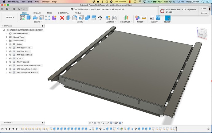
Here’s a Fusion 360 file I’ve done that to:

CNC Table for LR3, WOOD RAIL, v2, 78.74’ x 97’', 8in tall (v6).f3d.zip (504.4 KB)
There are 2 major reasons why it is recommended to make the X axis your shorter one.

  1. The beam is the weaker link. While the brace and rail structure is strong against sag, it can twist, resulting in dimensional inaccuracy.

  2. If you plan to cut the strut plate on the machine, the X axis is definitionally not long enough to do it. You need a Y axis longer than X in order to be able to cut the struts on your machine without tiling.

I was thinking about strategies to tile the strut plates, and it’s kind of tricky. The best I could come up with is to use the holes for the bolts, but bootstrapping that is troublesome. Alternately using the machine to cut blocks to position a strut cut to width on a table saw with an index for position could work. It isn’t that there aren’t ways, but I like to try to let the machine provide the accuracy rather than have it manual.

2 Likes

Re: tubes:

My plan that can cut to the very edges of a 49" wide MDF sheet calls for X-tube length of 56.102362". So, with your X-tube length at 55.11811", you’ll be able to cut a full 48" wide sheet, maybe a tad more.

Re: “How much material would a wide X and a short Y take?”

I have not had time to calculate that. Will try to do it over time.

Re: “I am not sure if the belt moving towards me (wide X) is easier to use”

It’s really up to your preference.

I think my biggest issue at the moment is that I lack a preference since all this is new to me!

I was only asking about material since in your thread with 3",6" and 8" tall tables you had that in there.

How would you compare the 3", 6" and 8" tables? Is 6" a good middleground?

I know the shorter one (3.625" version) can have its torsion box cut out of a single sheet. I know that any taller than that and it spills over to another sheet. Quick guess-timate, I’d suspect two sheets would do it.

Yes, I would expect the 6" to be a good middleground.

This basically means that my Y-axis has to be atleast 1400 mm usuable working area?

The thicker the torsion box the stronger the table. If it is just going to hold material for cutting, any thickness is more than enough. If you plan on using it for other uses that will carry weight, like an assembly table, thicker is nice.

More ribs is also equivalent to a thicker table.

If you want a 1400mmX strut plate yes.

2 Likes

I used the table with the unistruts

What about the legs? Can they be anything?

Or if you want to tile on 4x4 or 4x8.

Tiling the struts might be a pain, but you can add location holes in the file to match pins on the spoilboard. They don’t have to be exisiting features. Add a set of holes for each setup, move tbe stock so the holes go over your pins, run the next setup and add new holes, move the new holes to the pins, rinse and repeat.

I don’t think a couple of 1/8 or 4mm holes will affect the strut function, but if you don’t want to see them later, put them in a cutout and leave tabs on that one so you can remove and clean it up later.

1 Like

Is this table feasible with only a makita r70x router? No lowrider or similar.

The other version I referenced has some improved parameter structure and better timeline ordering. It handles parameter changes better. I don’t yet have one like that for the metal struts. I aim to work on that too.

For @Ryan 's suggestion for legs, please see his table design that I linked to at the top. I think it’s 2x4 lumber.

Awesome, will take a look as soon as i get home. Having a crazy day today.

I was thinking to do a light metal base with 6 legs and some casters with leveling as i did to my laser table

1 Like

A torsion box table can be made without a CNC. The quality of the work (precision of the cuts) will determine how well the table performs. Precision of cuts is one of the benefits of CNC cutting. That’s why I talked in the download page, and I and others talked on this thread, about ways to “bootstrap” cut this table, with your LowRider CNC, before you’ve actually built a table. It’s doable. See the bootstrap talk on the download page.

That said, it can be achieved without a CNC. The quality and precision will be impacted by both skill, effort, and how many helpful tools you have to bring to bear on it. A circular saw guided by a straightedge clamped to a board can give straight cuts as well as a track saw. A table saw can cut notches, but so can a small jigsaw. Getting one “master” X-rib made, and one “master” Y-spar made, can enable batching out all the rest by use of the Makita router, but with a “pilot bit” installed on it. The pilot part of the bit guides the cutting blade part of the bit on the uncut wood, which is below and attached to the pattern wood that’s already been cut.

One issue with batching them out with a router and pilot bit, is the need of attention to “overcuts” (aka “dog bones”) in the inside corners of the notches. Normally the radius curve of the bit forms a rounded inside corner that makes the notch unusable. Overcuts at the inside corners compensate for this. It’s a built in feature in CNC CAM setup (such as in ESTLcam). It’s possible for overcuts on a “master” template to be respected by the pilot bit, if the blade on the pilot bit is the same diameter as the overcuts were designed to be.