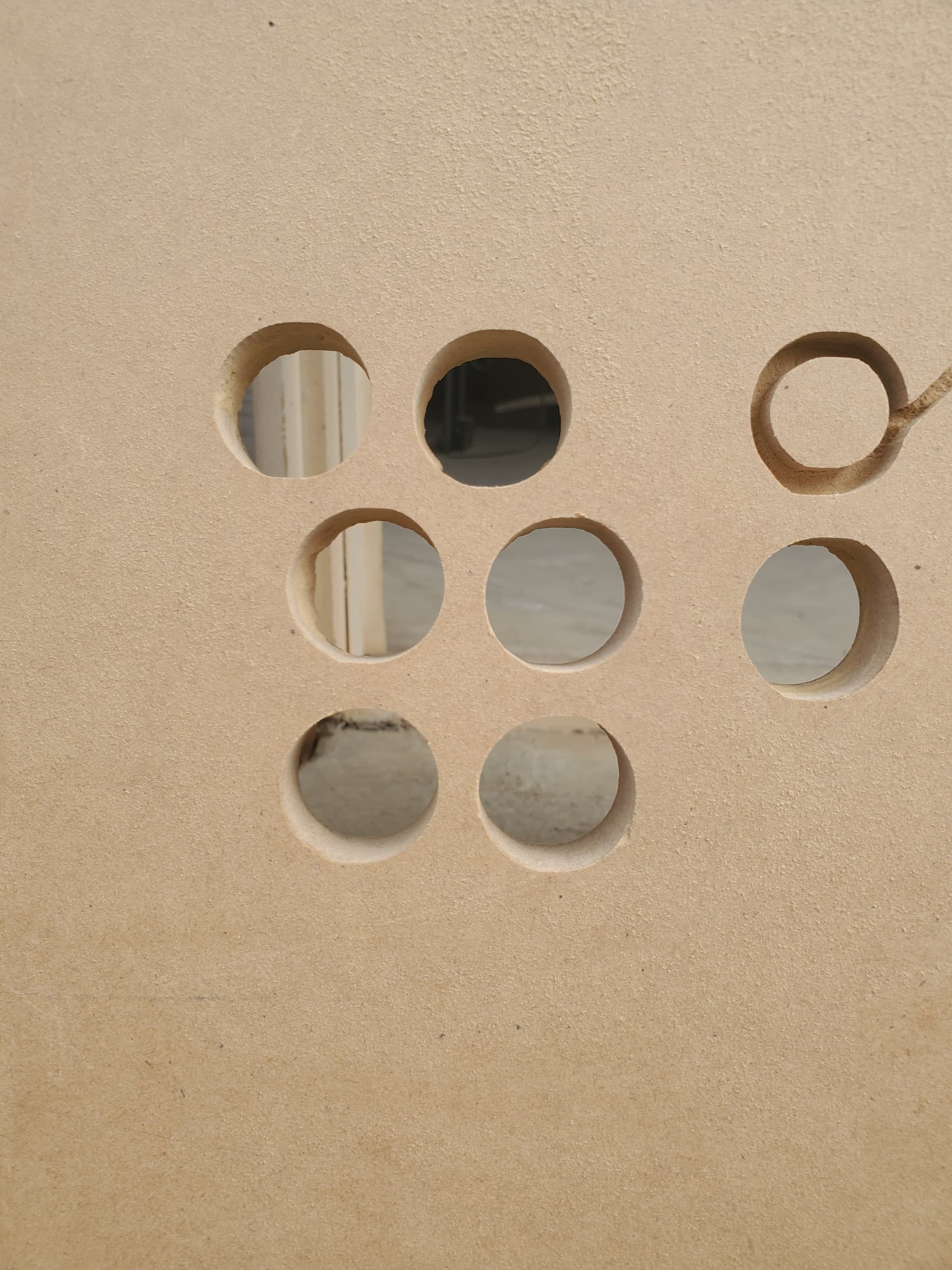
Ok, so my LR3 is on my parametric table with hidden belts and SuperStruts using Doug’s plans. I went to cut my first real cuts, an arcade cabinet, and the button holes are basically ovals, not circles.
I am using the SKR Pro, all standard equipment, 4x8 foot table, Kobalt router, the standard 1/8 endmill from the V1E store, speed is “5”. File sliced in estlcam and sent/operated in Repieter Host. Setting are:
3.18mm/1mm z+/90°/15mm feed rate/3mm plunge/24000rpm.
I tried arc on and off, circles cut path clockwise and counterclockwise. I tried changing the feed to 150%, 75% and 50%.
I had first tried this before with a 1/4" bit (changed parameters accordingly) and I messed it up due to a stupid issue with a cord, but the rectangle was pretty square and the circles were ovals too. So I had changed back to the 1/8" and noticed the circles and stopped it before cutting the overall shape.
Am I just being overly picky? The circle holes are 28mm. Does the LR3 just have issues with circles like how printers did a few years ago?
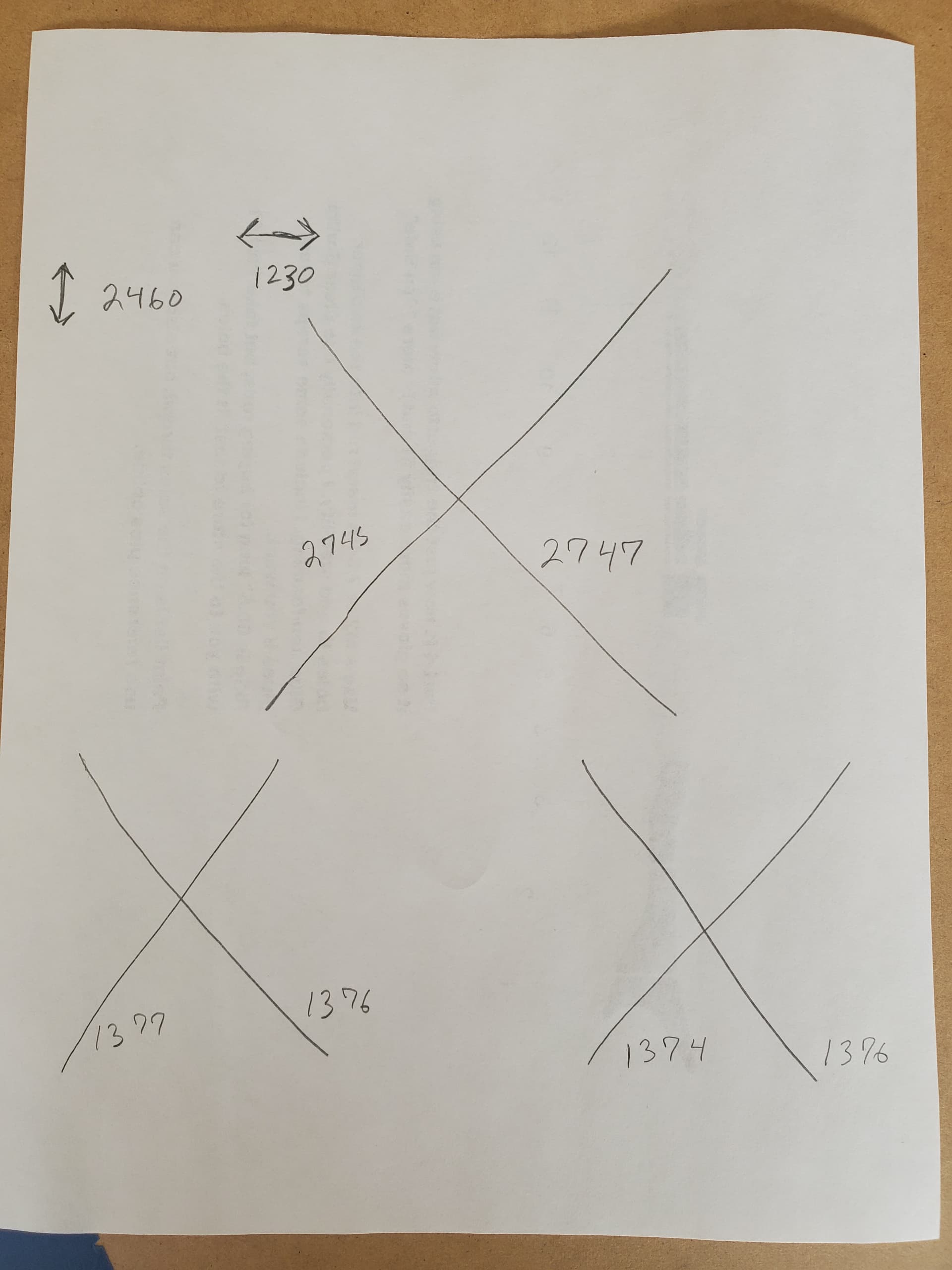
I went today and checked for squareness and I’m within 1-2mm. I checked full table, then front quarter and other front quarter. Here are my measurements in mm:
Any wiggle with the steppers energized? i.e., with the machine powered on, can you move the gantry at all (without putting real muscle into it)? Have you checked your grub screws? Are you popping wheelies along X travel? All glass-reinforced belts? (Steel reinforced belts become… rubber belts with steel shards within minutes, not hours.) With everything turned off, does the gantry move smoothly and freely? And finally, can we get some pics of the machine itself? Some of these guys can diagnose a lot just looking at pixels…
No wiggle when steppers on…everything is firm. No wheelies. The z screws are fine and irrelevant to this I feel. The belts are what V1E sells, real Gates belts. Everything moves pretty well when off. It’s not smooth line it’s on linear rails, but yeah. And pics will be in the next reply
Not the lead screws, the grub screws, AKA the set screws on the pulleys on the steppers. Sometimes, those get loose, and the pulleys get loose, and well…
With any form of troubleshooting, I find the best way is to go ‘I wonder if it’s X’, then figure out a way to check X.
If you think it might be out of square, I’d do something to test that specifically without leaning on anything else. Something with no force applied like milling some foam or taping a pencil/pen to the carriage then manually moving the machine through a square. That’ll tell you if it’s square and moving the expected amount on each axis.
If it’s square and the correct size with no force then maybe do something that needs force. Making a square pocket cut in a small bit of scrap, again just controlling it manually. If it’s still square and correct at shallow depth, do it again deeper and see if it stays square and correct.
The only other thing I can think to check at this moment, is… are the new Y stepper mounts rubbing on the metal struts in the Hidden Belts Mod?
Also, are the ovals oriented in all the same direction or random? If they are all oriented the same, are they “long ways” aligned with X axis or Y axis?
One other thought. If the ovals are all oriented the same, and all aligned with either X or Y, then which aspect of the ovals measures correct, and which measures as off? Are they correct on the skinny part of the oval, or the long part of the oval? Which axis aligns with the “correct” parts of the ovals, and which axis aligns with the “incorrect” parts of the ovals?
Yes, the ovals are always with the flatter sides parallel with the X gantry. The y parallel is 28mm, the x parallel is less, but not a bunch.
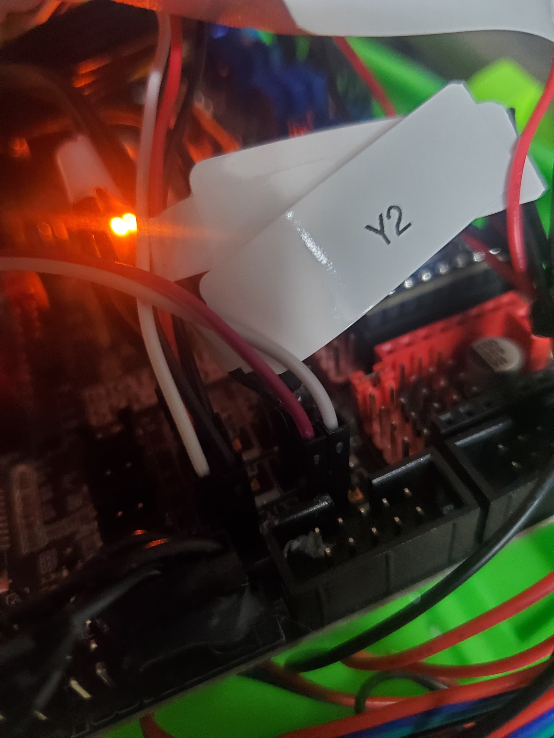
But honestly, I think I need to back this WHOLE train up. I had forgotten I never really sorted my endstops issues and just cut the parametric table on the floor bootstrap which honestly, turned out fantastic. So I just now started the squareness walkthrough and realized my y conduit was short, so swapped that out so I could home all axis. Homed x, good to go but get a m420 error at the end. Home y and only the conduit side one moves. Home all and the z increases and won’t stop and grinds. Opened up my case and the x min side Z endstops isn’t lighting up. So I never tried cutting the LEDs off or soldering the resistors. That will be tomorrow’s task. My soldering on endstops is good. I did recently buy 5 spares from the V1E store just in case. But regardless I’m thinking of just buying the Jackpot and being done with it.
So I actually have a question about that. There is slop between the bearings and conduit but you can tighten the bolts as much as you want but that will never close the space. All the tightening does is make the bearings not roll as easily.
So also, I added the resistors but that didn’t help. I’m 99% it’s because I had a horrible time soldering them. My next step was taking off the LEDs, which I did. Now my X and Y will home, but the Z1 absolutely will not. I tell it home z, climbs and z1 never triggers. I tell it home all and same thing. I checked the endstops connection, no fix. Got a brand new endstops and soldered together and no fix. I know the new endstops works because I tried it on the x axis and worked there but not the z1. Is it possible I just didn’t break the led off all the way on that one?
Very frustrating to be this close. I need to square this so I can fix those problems!
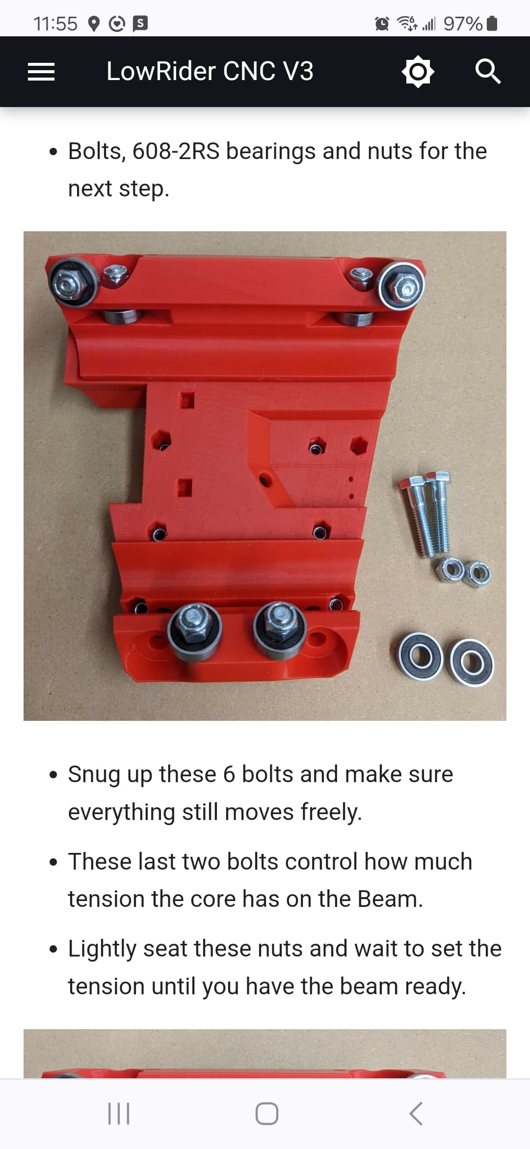
That’s a screenshot from the build docs with the relevant text. The last 2 bolts there flex the core print in order to bring the 2 brearings installed on the bottom closer to the bottom X rail. This controlls the tension so that the spindle doesn’t have any slop.
The 6 bearings shown installed in the core should only have enough tension so that they don’t leave the surface of the rails. The last 2 should be tightened just enough that all 8 bearings touch the rails.
After a while of using the machine, you start to see tracks from the bearings on the beam rails, you need to adjust this. If it was tight in the first place and you didn’t tighten down those last 2 bolts, the core may loosen, too, and you need to adjust this. I check my core at the start of each day I use the machine. I don’t know how many times Ive made adjustments, but I have a pair of 1/2" sockets that live on the shelf beside the LR now.
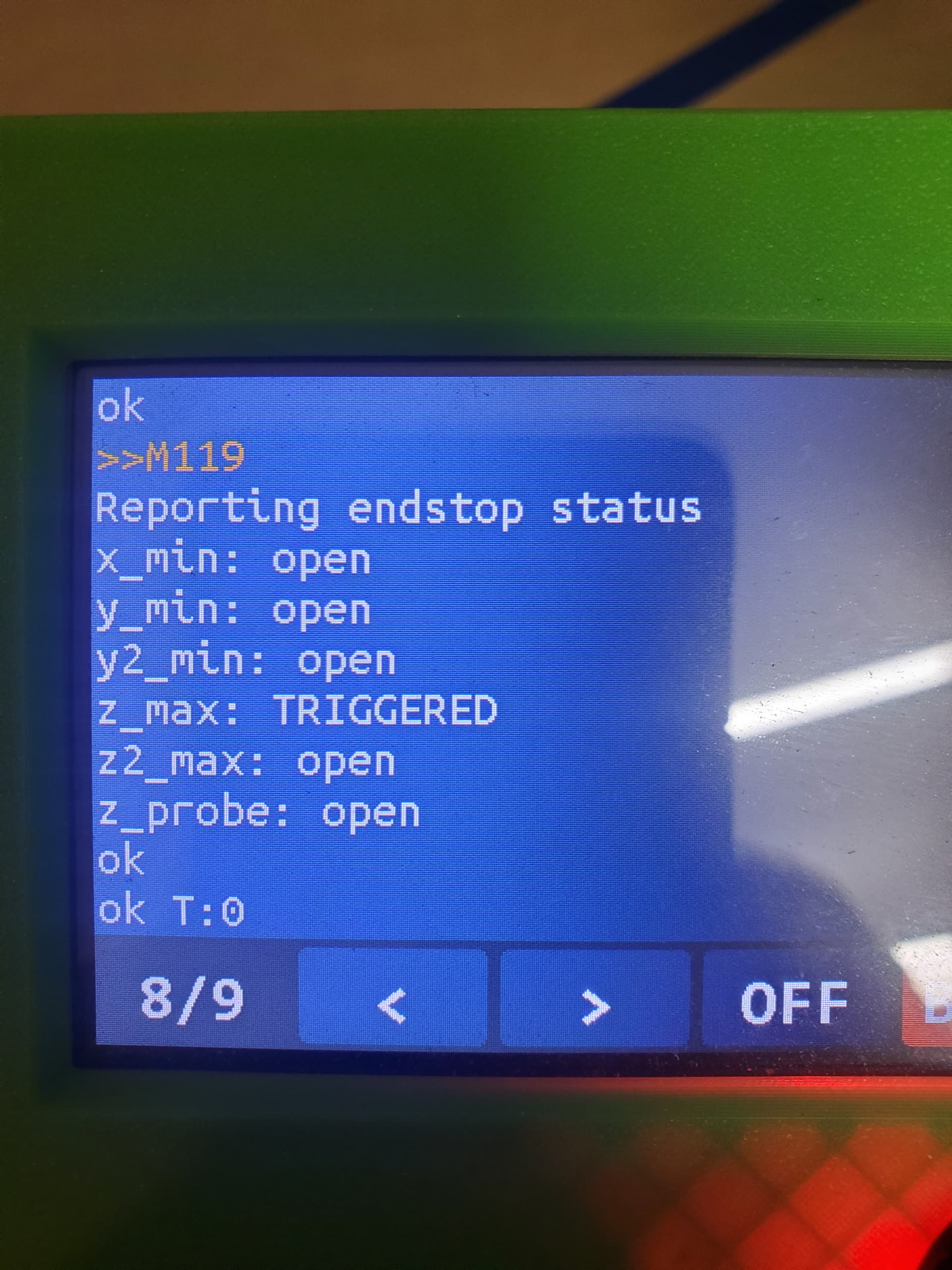
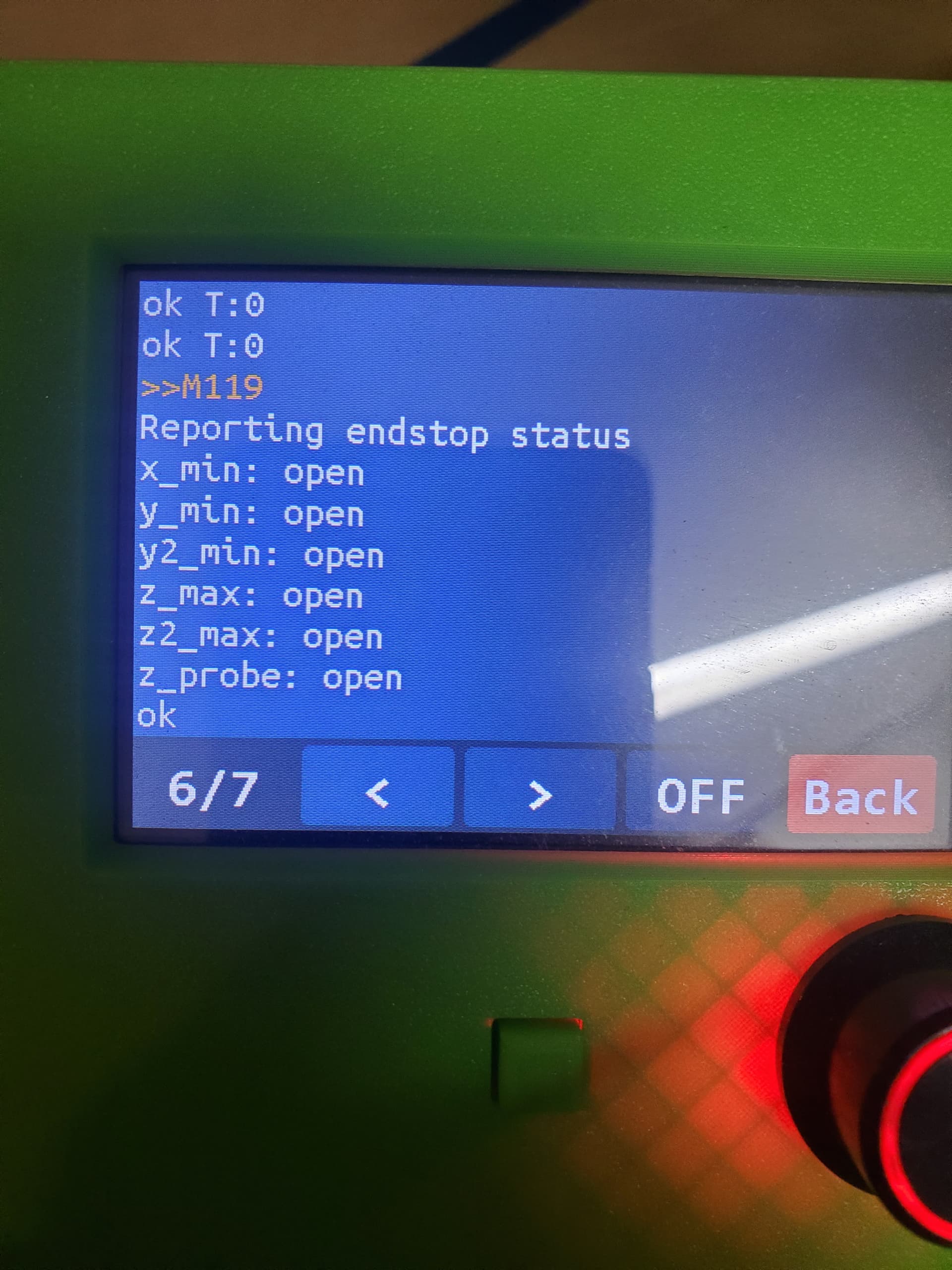
M119 is the gcode to report the end stop status. it can be used to diagnose what is going on.
So end stop problems come in 3 classes:
SKR Hardware, which is the most frustrating, but we’ve eliminated that
incorrectly wired. Wired as normally open instead of normally closed. (Unlikely, since you checked that it works elsewhere.)
wiring to the wrong connector. one of the things that is weird with the SKR configration, is a limitation with Marlin. The SKR Pro end stops are labelled for the motor driver that they light up beside. X, Y, Z, E0, E1, E2. Marlin MUST treat the first 3 as a stop at the axis minimum. Because we home Z to maximum, we therefore cannot use the “Z” stop as Z maximum. So by labels, we have:
“X” is X minimum
Y is Y1 minimum
Z is the touch probe input (Which we use probing to Z minimum to help you remember.)
E0 is Z2 maximum because it would nominally be X maximum and was otherwise unused.)
E1 is Y2 minimum
E2 is Z1 maximum (By position would be commonly Z maximum.)
My guess is that these aren’t in the right connectors, and you are using the Z connector for Z1 therefore it doesn’t trigger.
I’m wired exactly like the picture in the build guide
X1. Z2
Y1. Y2
Z touch Z1 (this is my non working one)
Even if I reach my hand around and hit the endstop, nothing. Even with the verified working endstops tester I made, nothing. I’m going to cut around on the led to make sure it’s fully gone, snip off the resistors that I added, make sure I didn’t accidently desolder the endstops pins. After that, I. Just going to buy a Jackpot
V1 firmware reports “open” for all of them except the Z probe as “open” if there is a short between signal and ground. Triggered means that there is no continuity between signal and ground and the pull-up resistor is adequate.
Hopefully you mean normally closed. the terminology is a bit weird, when we think of a light switch, “off” is when the switch is open, “on” is the switch closed. Those switches have 3 pins, a common pin that switches back and forth between the other 2. The normally open pin acts like the light switch. Press the lever and it “turns on” – this isn’t the one we want. The normally closed switch is on until we press the lever, then it “turns off” and that’s what we want.
From that report, I would think that either the wire to that z_max switch is broken, or the switch is wired incorrectly. To test, I would remove the wires from the E2 header, and put a jumper across the signal and ground, then run M119 again. if it still reports “TRIGGERED” as it does there, then there is a break somewhere that is not allowing the signal pin to be grounded. This might be an un-soldered pin, or damage to the circuit board.
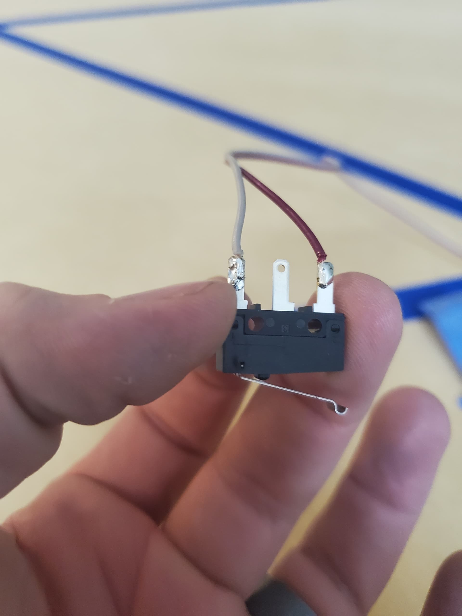
Yes, I mixed that term up. Long day. So as you can see, I even switch out to this little rig I made. It’s a brand new endstops from V1E, soldered, tested as a working endstops for the x axis. I place it on the Z1 and I get all open. But then I home all and Z moved up, I hit the endstop and it doesn’t stop. Just keeps going till it grinds out and I have to kill power.
I would test each one, when the switch is pressed you should be able to get each one to say “triggered” (Z probe is normally open, and says triggered when signal is shorted to ground.) You want to test so that you can get each of the 6 stops to say “triggered” when you want them to be.
With the LEDs in place, they should light when the circuit is open, so the Z probe would be lit when “open” and the light would go off when “triggered” so opposite behaviour.
If the end stops are reporting as expected, that homing behaviour is strange, unless the firmware were adjusted and recompiled.
The reason that I am getting you to go through this is that if it is a wiring or mechanical issue, you could buy a Jackpot board and still get the same problem. If you cannot get all 6 stops to say “triggered” then the problem may be something other than the board or firmware, then changing the board will be a very frustrating experience when you end up with the exact same problems. (Been there. Done that.) I believe that this is a resolvable problem If the firmware sees the stop as being triggered, I can’t see how it would fail to stop the motor, unless something else is interfering with the signal.