Yeah I mean like I said earlier, x homes, so that works. Y homes, so those both work. Z2 homes cause that stepper will stop and before I popped the LEDs off, the z probe was always on until I completed the circuit to trigger the probe and led out.
But I will run thru m119’ing each one regardless.
I did zero modding to the firmware.
I even have the endstops moved as low as possible but that doesn’t even matter cause my little testing switch should stop the z from moving when I press it and it doesn’t.
Also of note, the z endstops never worked even before trying to add resistors or cutting the LEDs off. Maybe I really do have a bad board or somehow shorted something way early into the build. Who knows. Oh, and I’ve even taken the sockets off so I make sure I have a more solid connection for the endstops too.
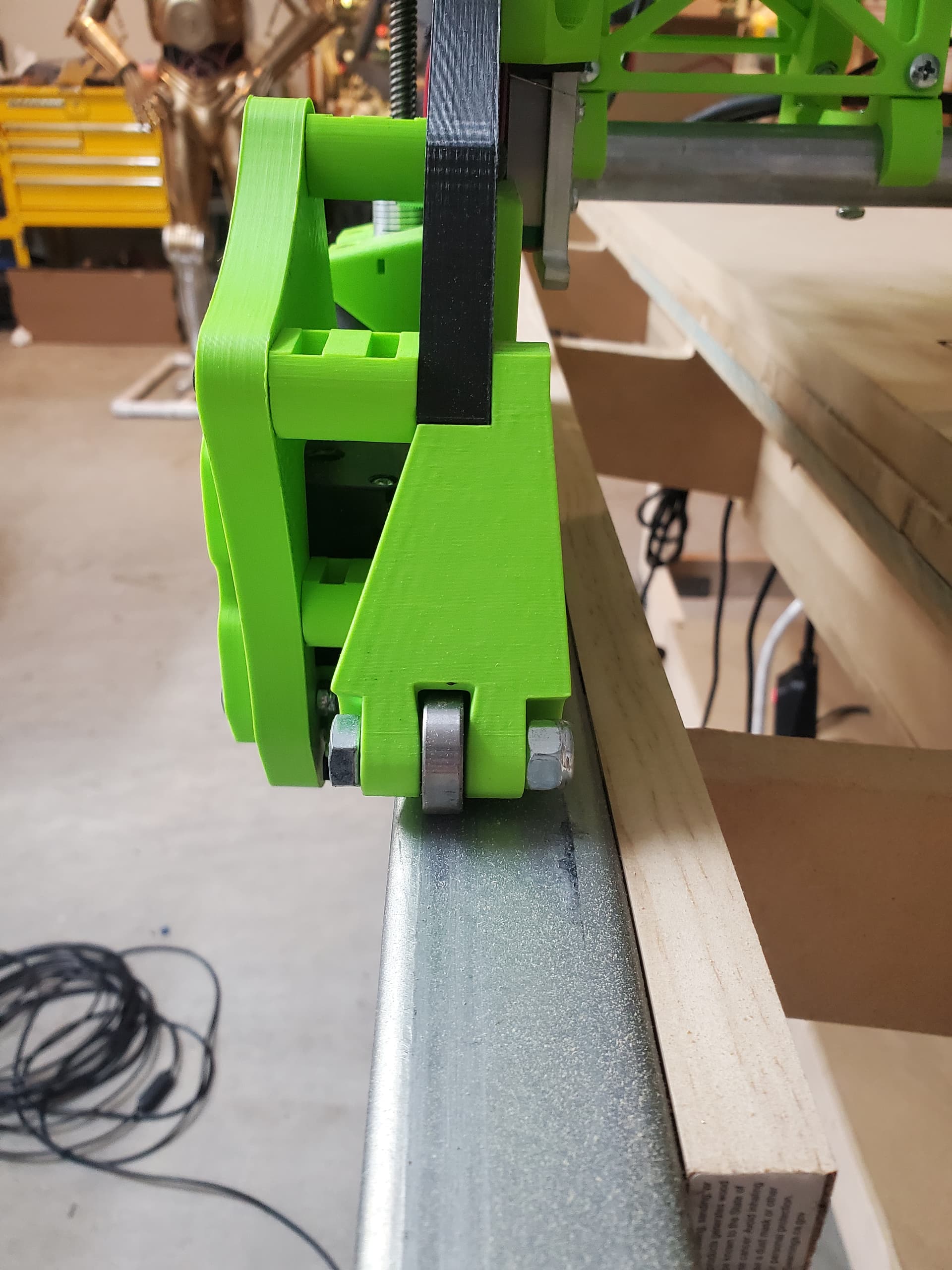
But one victory was that I did like you said and slowly.tightened those bolts and sure enough that really did cinch it down. Possibly will even totally solve my initial circle issue as the carriage was way more sloppy before I tightened those. So thanks for that!
If you have the Z1 and Z2 stops reversed, you can get a symptom like this.
The machine starts homing, and sends both Z1 and Z2 to the maximum. But let’s say that Z1 hits the home switch and the Z2 motor stops, because the wiring says that is the Z2 stop. The Z2 motor never gets to the top, and so never hits the other switch. Since the other switch never gets hit, the Z1 motor doesn’t stop.
This can also be the case if you wire the motors the wrong way around. It’s worth checking…
Naturally the same can happen if the Y1 and Y2 motors or endstops are reversed.
My particular build is weird, because the Y1 motor and Z2 motor share the same YZ plate. This is because it is easier for me to make the adjustments for squaring to Y1 and Z1, but as it happens, those are opposite sides of the actual machine. In getting that set up, I made a few mistakes with the end stops.
Pretty sure that’s not my issue, but I of course will do due diligence and check. But also, shouldn’t we be able to issue a command to just one stepper to jog? Like for instance a G1, then Y1 5, so just the Y1 moves 5mm? Sure would make you not level, but you could check to make sure everything is addressed correctly. And I know something like that is possible because on my V-Core , it does a z tilt to level. If I can ever get this working, I want to see if I could get the LR3 to z tilt. It would make it so your gantry is perfectly trammed and in sync.
Marlin has no way to do that. I can do that with the Duet board and RepRap Firmware, but there is no provision to individually move the motors of a dual motor axis in Marlin.
However, for trimming the level, look at the M666 command,. It’s original intent was to trim the offsets for a delta style printer, but also works for dual motor axes to have a specified amount of “pull off” from the end stop when homed. Non homing moves will always move the motors in lockstep, barring skipped steps.
So far as I know, FluidNC on the Jackpot is the same. Homing moves will stop one motor or another when they get to an endstop, and you can configure a pull-off value from that endstop to fine-tune the homing process to get the Y axis square and the Z axis level, but you can’t move an individual motor. (Well, you don’t need to.)
So long story short, I think I fixed it? I did a bunch of things. I swapped out the z1 endstop to my endstops that I have been using as a tester since I know it works. Monkeyed with the connector to make sure it can seat fully on the board. Flipped endstops and no my z1 is the conduit side and z2 is belt side.
Now I’m going to test the touch plate this afternoon and then squaring
Just a quick update. First, thanks for all the input. I did a few things.
Ok, I totally undid all my endstops and started from scratch and learned I had a few things mixed up. I removed the endstop sockets from the SKR board and that helped as well as totally replacing the endstop and wires on the Z1. I then was able to make it home all axis. The z probe worked like a charm too. In addition, I went into TinkerCAD and designed a little 60mm block with negative space to act as a brace for the Z when I power it down. That way everything stays trammed and close to even. I saw Doug Joseph has a wood block, but this was faster and worked better for me. I’ll share if anyone wants the file.
Next, I went to square the entire 4x8 bed and saw that when I went to Ymax limit and Xmax limit that the YmaxXmax was not even. So I did hats likely not the preferred way, but I carefully measured and manually pulled the carriage back. I’m not describing it well, but what I was solving was that the position of the Y steppers were not even which was causing the Xmax to be slightly behind where it should be. I then redid the max and min points to find the diagonal measurement. I measured Y as 2460mm and X to be 1230mm, so just shy of as large as I could go. The diagonals measured as 2722 and 2723, so 1mm! I was surprised that after just that one minor fix and 2 go arounds squaring that I was able to physically square without firmware offsets.
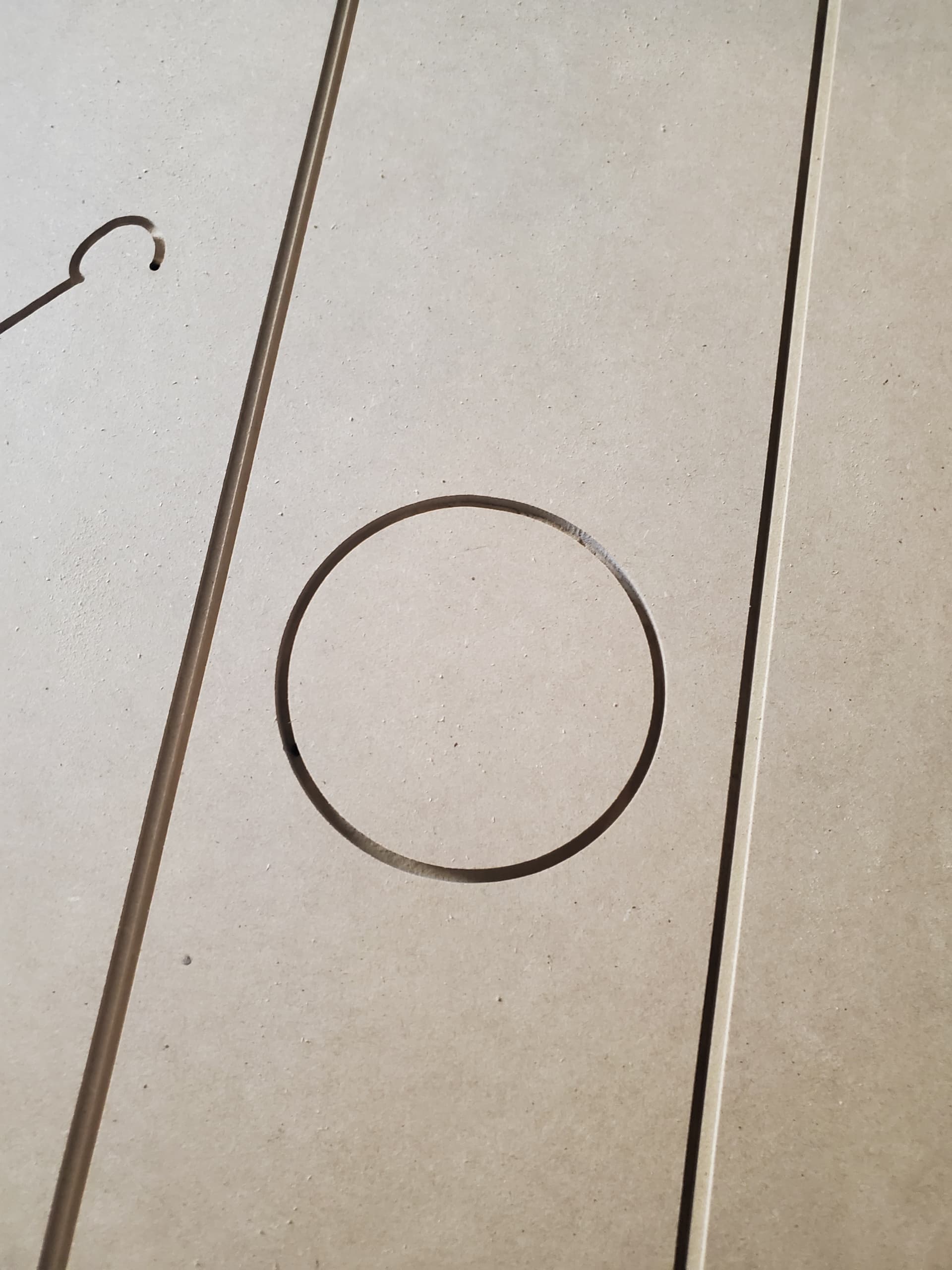
So I am just now cutting an arcade cabinet speaker plate that’s 800x120mm roughly and has two large circles and pleased to see that the circles look great and so does the overall squareness of the plate!
Oh! And in the Xmin of the hidden belt side without the conduit, I added the slightly longer stepper offsets. That allowed the pulley system to not rub and also put my bearings more on the Superstruts as well as fixed the slight flaring out of the lead bearing.
Speaker plate cut perfect except Repieter Host crashed but my part was basically done. Test two is a nameplate from brother in laws wedding. The fonts cut very, very well.