The general idea goes like this:
Motor torque is proportional to winding current, as is the IR loss due to wire resistance, while back EMF is proportional to rotational speed. The voltage available to drive the winding current is thus the power supply voltage reduced by the IR loss and back EMF.
The steppers have 200 full steps per revolution, with the controller dividing each full step into microsteps, typically 16 or 32, for a total of 3200 or 6400 microsteps/rev. Each microstep has a specific relation between the two winding currents, defined as the sine and cosine of an angle running from 0° to 360° every four full steps.
The vector sum (RMS value) of the two currents adds up to the nominal winding current set by the twiddlepot on the driver board. For example, a 1 A setpoint will produce 0.71 A current in both windings during the 45°, 135°, 225°, and 315° microsteps. Anything that changes the relationship between the two winding currents will affect the direction of the force applied to the rotor and disturb its rotation.
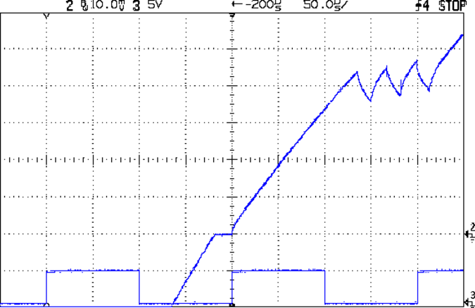
The controller must change the winding currents at the start of each microstep, then stabilize the currents at their new values, by applying the power supply voltage to the ends of the wires leading to the motor. Because the motor winding inductance limits the current’s rate-of-change, the controller uses PWM to switch the voltage much faster than the winding’s time constant to make the average current closely track the desired setpoint. That’s the sawtooth part of the waveform, over on the right side:

Here’s how it all fits together.
The long rising slope in the middle of the screen shows this equation in action:
V = L Δi/Δt
Where L = winding inductance and Δi/Δt = current rate-of-change.
The effective voltage V at the winding is the supply voltage reduced by the IR loss and the back EMF. You can’t measure the effective voltage directly, but it pops out of the equation when you know the inductance (from the motor datasheet) and measure the Δi/Δt from the rising slope. The linkie above the picture has the calculations for a different motor & supply voltage.
So the power supply voltage, current setpoint, and back EMF determine Δi/Δt. The current setpoint comes from the motor datasheet (it’s a “1.0 A” or “1.5 A” or “2 A” motor), so you know the IR loss in the wires. The back EMF comes from the motor speed, which you pick to be faster than anybody else’s MPCNC [grin].
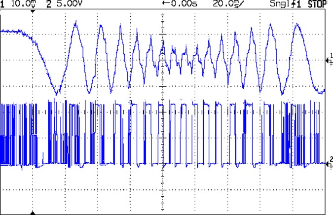
As long as the speed remains low enough, the controller can change and regulate the winding currents during each step. When the speed gets too high, the controller loses control and produces the wreckage in the middle of this trace:

The bottom trace shows the controller’s PWM switching, which should always be similar to the narrow spikes over on the left. In the middle, where the motor reaches 60 mm/s, the “PWM” degenerates into wide pulses as the increasing back EMF reduces the available voltage, the Δi/Δt falls, and the current can’t reach the proper value during each microstep. Because the current doesn’t reach the setpoint (the peak values as the motor starts and stops), the torque drops and the motor tends to stall in the middle of the move.
I picked absurdly high speeds to show the effects for the Circuit Cellar column, but when folks kvetch about “missed steps” and suchlike, you’re seeing the equation in real life. If the motor speed remains low enough, then a low power supply voltage works just fine.
However, the power supply voltage provides the only knob available when you feel The Need For Speed or the need for more torque at a given speed. In round numbers, going from 12 V to 24 V adds enough headroom to make 133 mm/s = 8000 mm/min traverse speeds possible, if not practical.
I did an analysis of the crappy stepper motors Makerbot used in the original Thing-O-Matic, back in the day, with truly grisly detail. It’s more than you really want to know, but provides more info on most of the topics. The comments were enlightening, too.
(Ryan: This may be a dupe, but might be better worded than my earlier attempts)


