I just posted this on thingiverse but then realized that here would be the better place.
I just got my first laser for my MPCNC and I am struggeling connecting it.
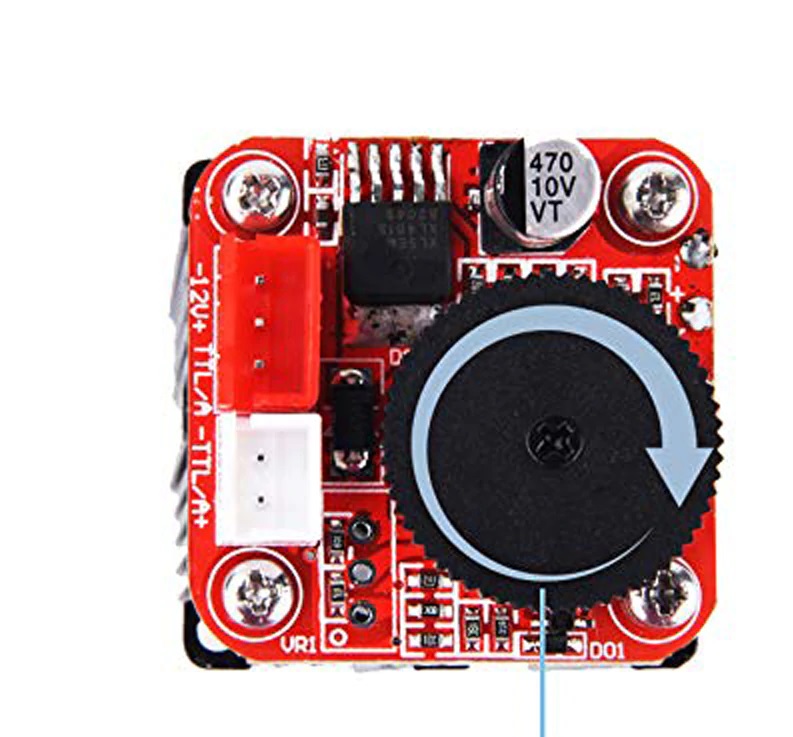
There is a 3pin connector and a 2pin connector.
The red one has a +12V, -12V and TTL/A Pin
The white connector has -TTL and A+ on it.
Now, both 12V Pins go to the power for extruder or heatbed on the RAMPS (D9, I think this is)
But what about TTL? This, as far as I know, should go to Pin 44 and is 5V.
But what pin should I use? Is it the TTL on the red connector? But this could be 12V.
The white Pin could be TTL 5V and Grd. Should I use that one?
The 12V should come straight from the power supply. Just wire it up in parallel with the ramps.
It’s weird they say -12V, when really, I suspect that is ground, or “the negative side of a 12V power supply”
For the ttl, if it can handle 12V, the easiest way is to connect it to the negative side of the fan port, and control it with M106/M107. It may be inverted though, where 100% (M106 S255) is actually off.
The next easiest thing to do (or if it can’t take 12V PWM in) is to change the value of the fan pin in the pins_RAMPS.h to a 5V pin (like servo0) and then use that pin for TTL. I suspect the two TTL ports are wired to the same pin.
Hi Jeff,
thanks for your quick answer.
So am I getting it right that the TTL on the 3-Pin Connector should be12V, right? So I should not connect it to Pin44, then because that would be a 5V-Pin?
The way I understood it is that you need the fan port (D9?) to switch the laser on and off and the 5V-PWM port to change the power of the laser. At least that is what this German website says: http://www.3d-proto.de/index.php?p=project_LaserCutter
So I should wire the 12V to D9 in order to switch it on and off using M106/M107.
Then I wire the TTL/A+ on the white wire to Pin44 and that way I am able to control the power as well.
Okay, I managed to setup the laser and it works now. I have not tested extensively but it seems to work fine.
I wired the 12V as said by Jeff. They go directly to 12V Powersupply.
The TTL goes to Pin D6, which is one of the servo pins.
This is the standard Marlin wirering for the enabled laser menu.
As for wiring on the laser, it seems not to matter if I wire it to the TTL on the 3 pin connector or on the 2 pin connector. Both control the laser. I measure voltage from gnd on the laser to TTL on the laser with just the power connected and there was no current.
For the sake of just having one connector I now have wired TTL to the 3-Pin_Connector
I can now switch on the laser via Marlin menu and also choose the power.
There are more than one way to do it. I don’t like the idea of the extra current going through the board. I also don’t need to toggle it on or off outside the ttl pin.
It doesn’t surprise me that those two control pins are the same. I think it is tolerant of 12V, but can be triggered by 5V and it only looks at duty cycle. Glad it is working for you.
The A in TTL/A is analog. ie. you can use it in TTL mode or analog mode.
TTL implies 5V and in this case the assumption is that the input is PWM (pulsed depending on the intensity you want).
But you can also change the voltage (analog) instead of PWM.
Usually with lasers like this, the 3-pin connector is for 12V, ground, and PWM (this can be connected to the fan output); and the 2-pin connector is for TTL (5V) PWM.
You are right in being confused. Thankfully they usually are 12V tolerant so it is hard to burn them out by accident.
Sorry Yvan but your explanation makes no sense to me. AFAIK these ‘banggood’ type of combined power brick/regulators usually have four sockets, one for a 12v fan output, one for a 12v power input, one 3 wire laser connection and one 2 wire laser connector. If you meter the pins out you will find the 3 pin laser output connector has two pins, the ground and the signal, commoned together with the 2pin laser connector. Both of those connectors are PWM outputs. The reason that there are two possible laser connections is that some lasers have a single +,- and pwm signal connector and some lasers have separate power and PWM signal / ground connectors… nothing to do with an ‘analogue’ mode.
As far as TTL goes, this is something I think the Chinese have ‘adopted’ just because the signal level is set to +5v… it is nothing actually to do with TTL in the traditional sense. Most, if not all, PWM input signals for lasers MAY be 12v tolerant (they sure as s*** will be +5v tolerant) BUT without definitive knowledge of the input FET’s characteristics you cannot be sure.
The laser itself does work flawlessly and I can switch it on and off via m3/m5.
I am, however, facing the issue that I have stops/ pauses when running the laser g code.
It seems like the MPCNC needs some time to think about what to do next. This causes dark burns in the wood.
It happened when creating a gcode using the JTP plugin in inkscape.
Then I tried to use the raster2laser plugin but here M03 does not turn on the laser. Manually sending M03 does turn it on.
The stops are probably Z moves not sure how to stop that with Marlin but using laser mode in GERBL and M4 instead of M3. Maybe remove Z moves or make them really fast
well, if I interpret the gcode correctly, there is no Z-move plus I tried once again using the Inkscape Plugin and setting Z-Movement to 0 and it still was the same problem.
It is my understanding that the stop/start motion with Marlin and M3/M5 control is because it’s being treated as a spindle… with the need to dwell for a moment with every change in spindle speed. Lasers, of course, change instantaneously and don’t need the dwell. This is the reason I now use GRBL for my laser machines… it has a “laser mode” (with M4/M5 control), specifically designed for smooth motion and dynamic power adjustment with feed.
I don’t think that will work without the GRBL 1.1f (or later) firmware…
Here are two similar burns… one with Marlin and the other with GRBL. Note the Marlin overburns with each start/stop (accel/decel)… while the GRBL burns are much more uniform
Actually I found a solution myself.
After you said that Marlin waits for the spindle to turn up, I had a look at the firmware and the Configuration_adv.h
There are following lines
  #define SPINDLE_LASER_POWERUP_DELAY   50   // (ms) Delay to allow the spindle/laser to come up to speed/power //war 5000
  #define SPINDLE_LASER_POWERDOWN_DELAY 50   // (ms) Delay to allow the spindle to stop // war 5000ms
I changed the 5000ms to 50ms and now it works like charm even with M3.
Thanks for the video!
What software do you use for the pictures if I may ask?
I dont know how to laser pictures.
Since it’s been a while and I’ve forgotten most of the details, I think these posts have all the information about the software I was using at the time I was doing these tests…