I just smoked an $80 block of maple doing a 3D relief map of a local trail. I have no idea what happened–curious to hear if anyone has any ideas. The workpiece was 13” square, 3” thick. All prep work was done in ESTLCAM V12. The model files were generated using USGS DEM files, a script that turned them into STL files, SolidWorks to do the trail trench relief, and then STL export to ESTLCAM to do the gcode setup. QGIS was also involved.
Machining is divided up into 3 phases–roughing cut (1/4” end mill), first finishing cut (1mm ball nose tapered), and second finishing cut (same bit). The plan was to do epoxy fill in between finishing 1 and 2–finishing 1 includes a 3mm deep groove that represents the trail, and finishing 2 would take off the same contours as finishing 1 but 1mm lower and without the groove..
Roughing cut was fine–no issues; took ~18 hours. First finishing cut started out fine. After about 8 hours, I noticed that the cuts were a little rougher (a little bit of fuzz in between adjacent z-levels in some spots) and that the unit was making some cyclic vibrating noises during z-axis movement. The profile was still quite good, however. I figured something needed tightening eventually, but wasn’t concerned since the movement still seemed pretty smooth and I was going to do finishing cut 2 later and could tighten things up to try and remove the vibration before that last pass. I have no idea if this is related to what happened next….
All of a sudden, I hear the sound of major material removal; by the time I make it downstairs, it’s drilled two huge holes in the workpiece and carved a decent sized trench along an axis extending from one hole to the other. See pic below (red line is axis of trench; the curvy trench is supposed to be there–it’s the trail).
I’d done this same process a few weeks ago on the same equipment with an 11” square, 2.75” thick workpiece and using a similar approach (different model files, however–due to aspect ratio, had to change extent of map). No issues and it turned out gorgeous–there’s a photo below of it before I completely finished it.
I checked the gcode that I was using (attached), and I can’t see any odd low points that would cause it to suddenly start drilling straight down. A preview of the gcode shows nothing like these features. It seems like it must be the controller misinterpreting/misexecuting the gcode. But I’m no gcode expert so maybe I missed something.
The mill itself is an MPCNC Primo, but the control board is from ~2020. It started out as a Burly, but I re-printed all the parts as Primo this year and upgraded it. The controller stayed the same and is a Rambo Dual running Marlin 2.0.x (whatever it shipped with–never bothered to update it, I think–maybe that was a mistake). The dual endstops are enabled. It is attached to a V1 “full graphic smart controller (big)”, which has the SD input, display, and scroll dial/selector. I’ve never had it do anything like this before–the issues that I’ve had have usually been when a workpiece breaks free and bounces around the table.
Not sure if the workpiece is salvageable–the lowest point on the map is pretty thin, so even if I plug the holes with dowels and shift it all downward to try and eliminate the trench, I may run out of material at the bottom.
There was one thing that was different between the earlier successful attempt and this one (aside from size). To make the trail trench, I had to import the terrain STL file into SolidWorks and then import the trail DXF file into the same model. The terrain STL was turned into a solid body. I then did a bidirectional offset from the 2D trail path to make a ~1mm wide “trail” outline; this was then used to split the terrain solid model so that the trail portion was able to be moved downward by 3mm relative to the remaining portion to make a terrain-following trench. I then re-joined the trail portion to the terrain portion in the previous successful attempt so that they were one solid part. In the latest version, I didn’t bother to re-join the two portions after moving the trail portion downward since it didn’t seem to matter. But now I’m wondering if there was a stray vertex down at the bottom at the interface between the trail slice and the terrain and that vertex maybe registered as being a feature to machine (and it wasn’t there in the previous one because I joined the two bodies). The preview doesn’t show such movement, however, so I think it’s probably unlikely.
Any thoughts/ideas on what happened? And how to prevent it from happening again?
Cheers,
Christian
PS: Didn’t include the CAD/STL output since they are gargantic.
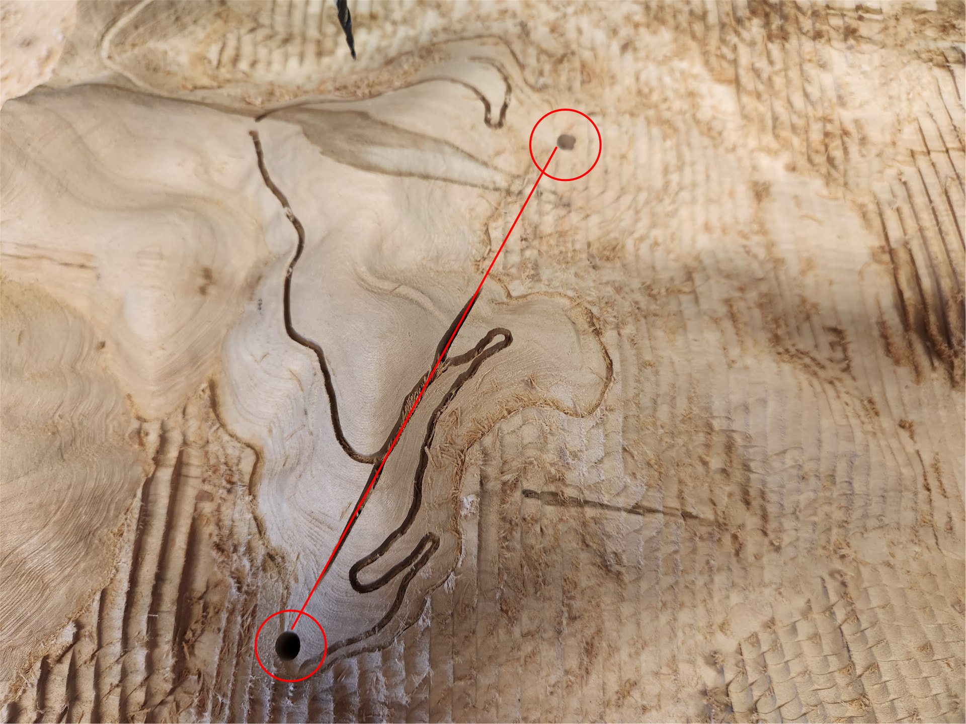
The casualty….
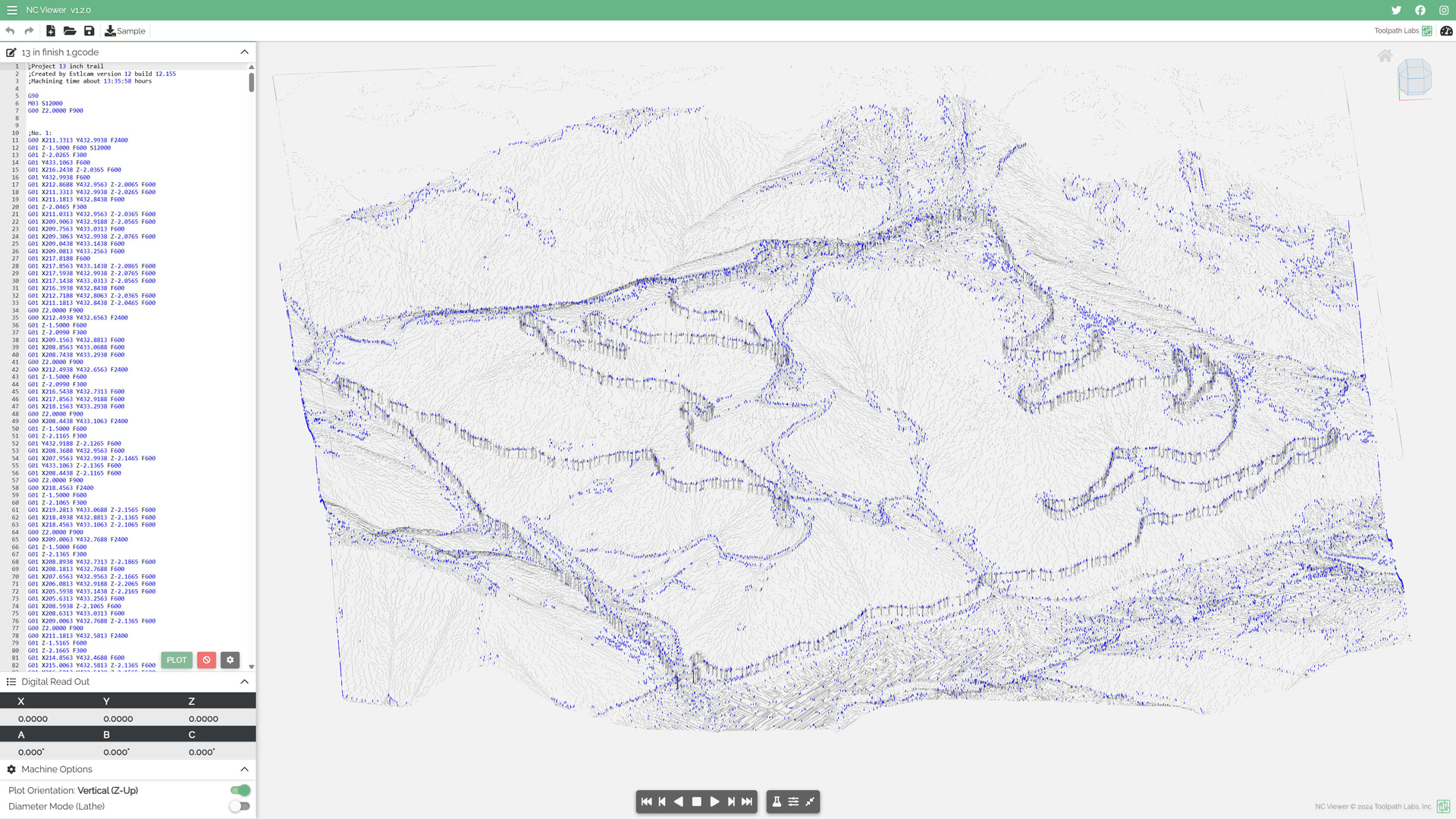
What the preview looks like of the finishing program (first stage)….
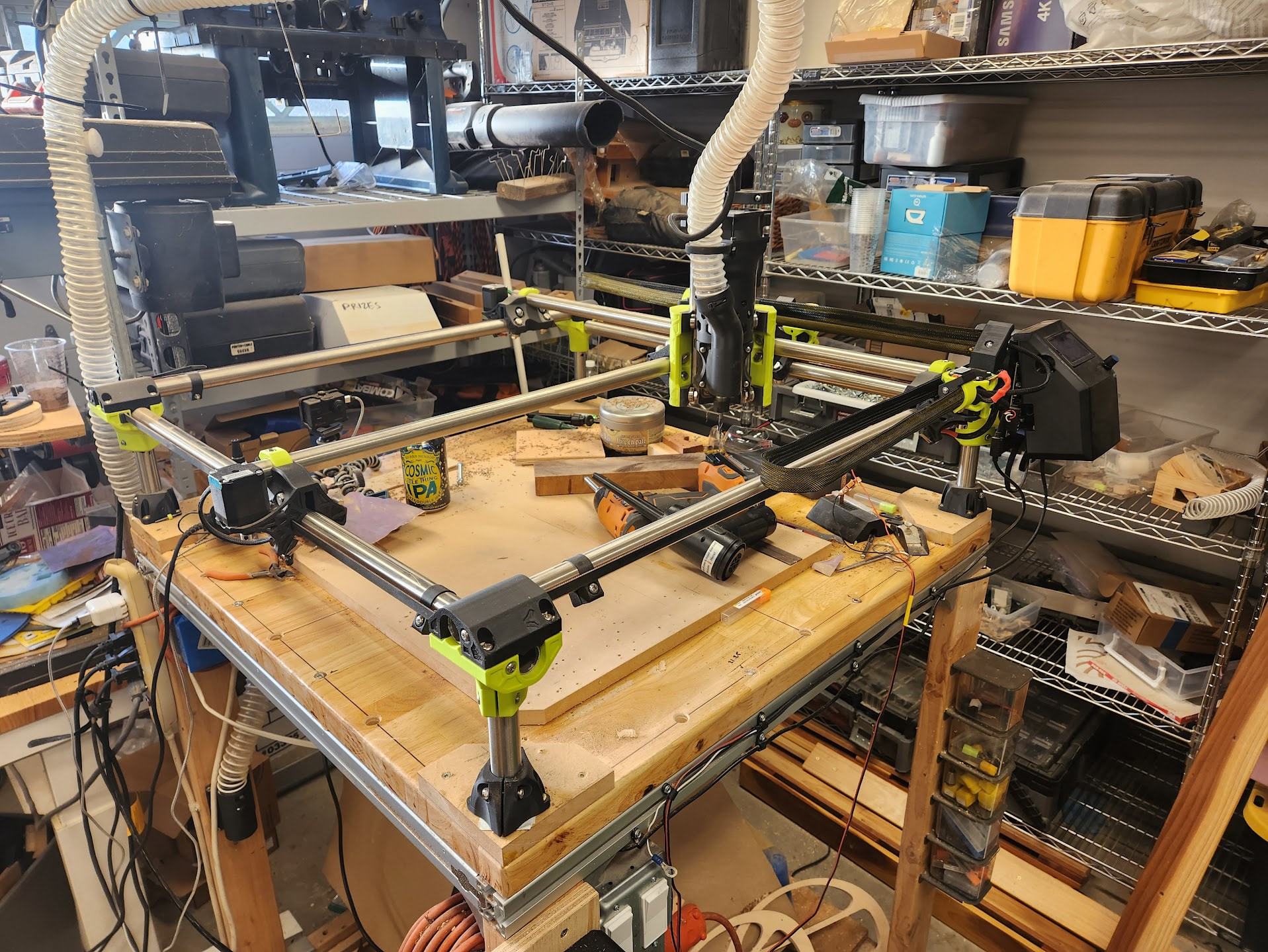
The MPCNC…it’s pretty big, but has worked well until this.
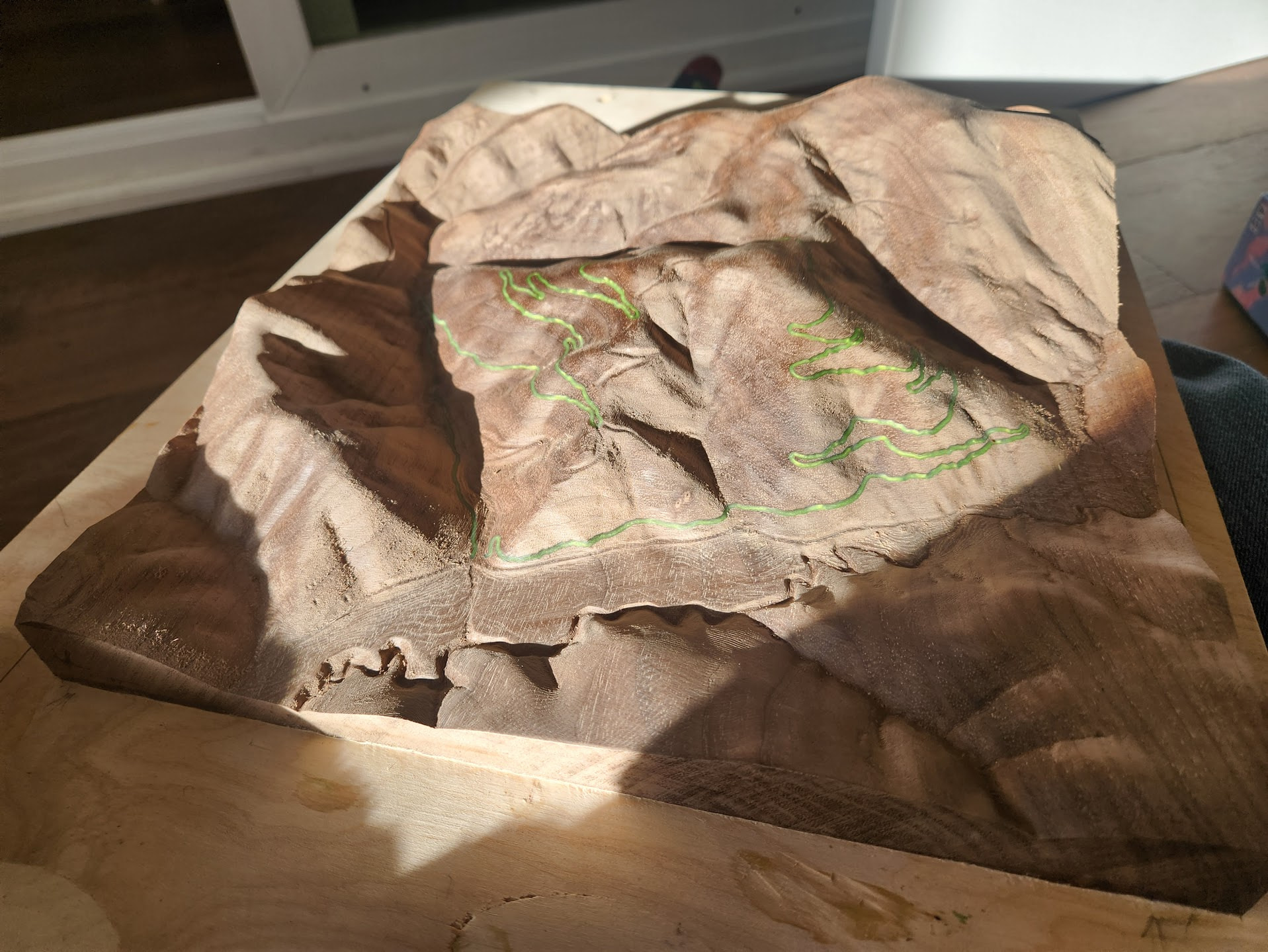
The previous attempt at something similar.
13 in finish 1.zip (2.6 MB)


