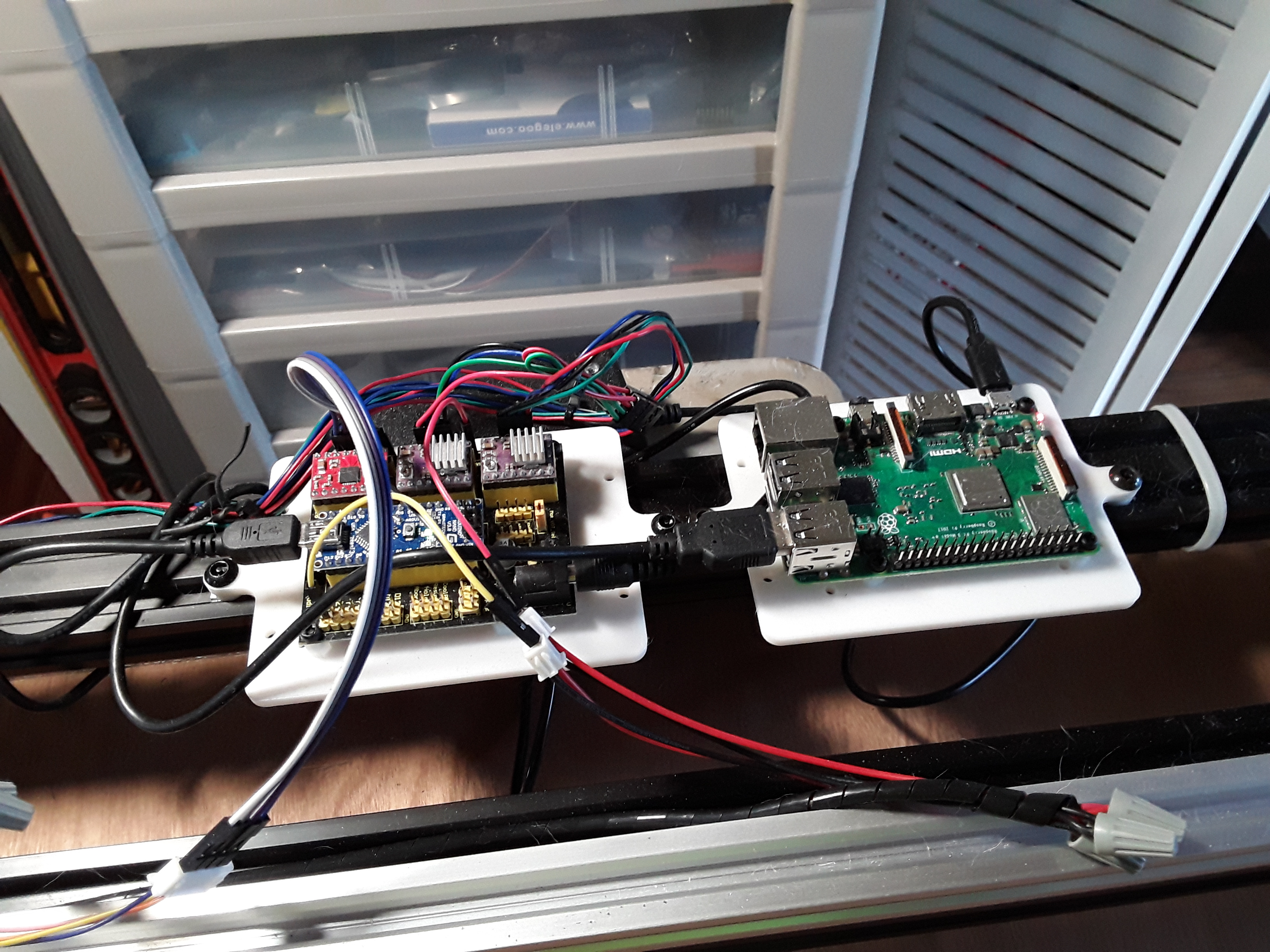
Where is your 12v line for the laser hooked up? I can’t tell from that photo.
I know it’s hard to see but there are red and black jumper wires (near the yellow wire) going to pins on the other side of the stepper drivers… there’s a 12V pin and a GND pin over there, that is also feeding the motors.
1 Like
I started to test this board out today, but am not 100% sure of the direction of the DRV8825 drivers since there do not seem to be any markings on this board. This page:
https://forum.arduino.cc/index.php?topic=595435.msg4046056#msg4046056
shows the best that I can tell for the pin directions. It shows a 2130 driver, but GND& DIR pins seem to be in the same orientation as the DRV8825 which I will use. Does this look correct? I checked for voltage on each of those 4 motor pins, but did not have a driver in place, so guess I need a driver connected before any voltage shows up? can you tell me which of the 4 motor pins has the 12v on it? I attached my multimeter ground lead to a known ground connection on the board & used the + lead to check other pins for 12v as that seemed a safe way to do it. If this starts to be more of a pain to hook up, I might just wait for my eleksmaker board to come in.
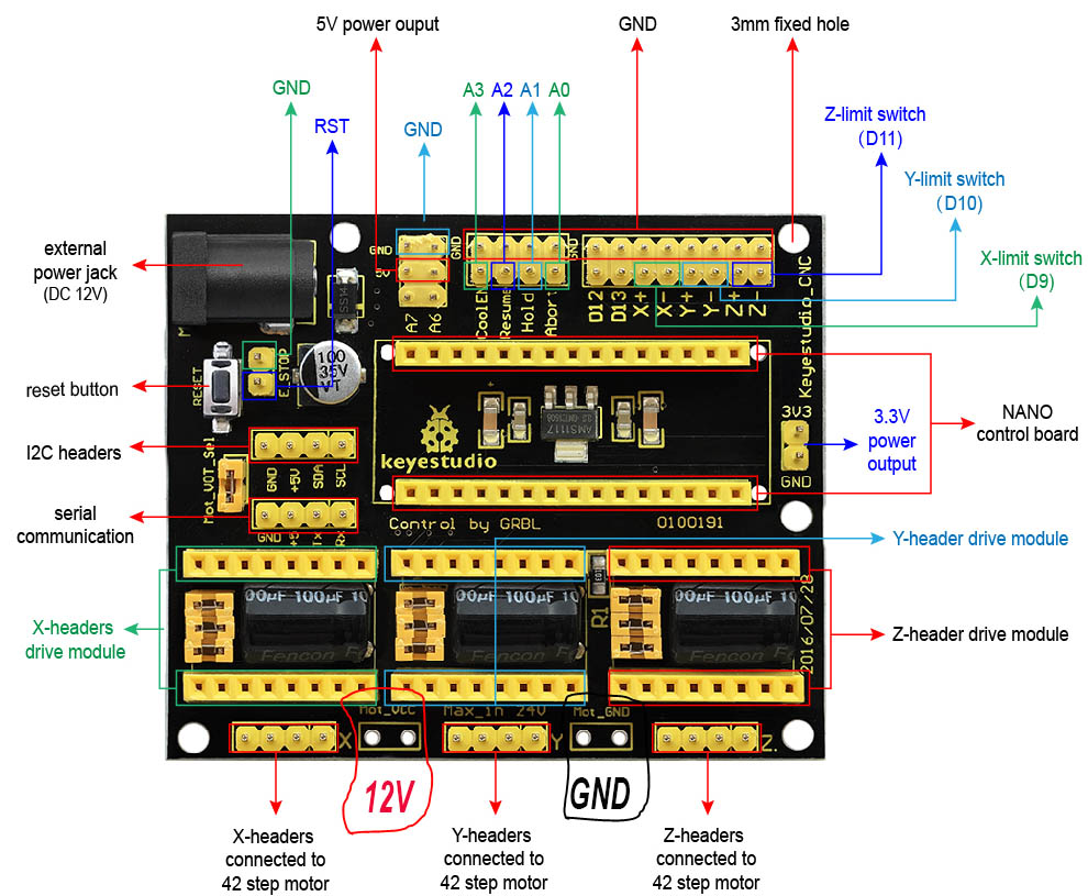
IF you are talking about the Keyestudio board, refer to my working board picture from above (repeated here)… there are a couple of DRV8825 (X/Y) and a A4988 (Z) installed on the board.
1 Like
Not sure how I missed that from the photo & had my coffee today also. Thanks for setting me straight again. I am mostly working on my back deck project, so have to fit this project in when it rains.
1 Like
Ok, I added the X & Y DRV8825 drivers & set their vref to .43v which is the range I usually start them in. I also found the 12v line as shown in the below photo. I circled the 2 pins to the right of the X motor connection that show 12.4volts(marked on the board as Mot_VCC) & the other 2 pins to the right of the Y connector seem to be ground (marked as Mot_GND) when using the ohm test between another known ground connector.
We have storms this afternoon, so I may wait until tomorrow to test the motors & then the laser.
1 Like
What would be some good suggested grbl settings for this machine. I have:
$100=160
$101=160 <---- GT with 20T Timing Pulley and 1/32 mm micro-stepping(DRV8825).
$102 =160<---- Not using Z axis, but set it to same number for now.
I also could not get $$ to work with the cnc.js with the V1 install, but that might be my ignorance.
Thought I had compiled the grbl firmware wrong, but I did get the settings to show up using the openbuilds Control software.
https://software.openbuilds.com/
This was a lively debate recently in another thread… but the simplest way IMO to get in the ballpark quickly is simply rubber-band a skewer to the carriage and command a move over a ruler laying on the work surface in line with the axis you want to check…
Command a small movement – say 10mm – and see how far it actually moves. Check it several times. Then use the following to compute a new steps/mm value…
(commanded move / actual move) * current steps/mm setting
For example, if the current steps/mm is 160, you command a 10mm move, and consistently measure only 9mm of movement, your new value will be (10 / 9) * 160, or 178.
That’ll get you really close. Do it again with as large a move as your axis allows, measure as accurately as possible, do the calculation (I keep 2-3 decimal places)… and you should be very close to calibrated. This will also work… even if you should accidentally install a 16-tooth pulley or mis-jumper the micro-steps 
– David
Using
as I have done in the past, the 160 should be correct for the GT2 belt & T20 timing pulley, 1/32 microstepping & 1.8deg motor. I will test that though to make sure. I was just wondering about the other grbl settings.
After wiring the jumpers on the keyestudio board, thought I would draw up the circuit diagram to make sure this looks correct. I had to bend back the 3.3v pin on the board so the usb plug could connect to the nano board. @dkj4linux & @dart1280 see if this looks correct?
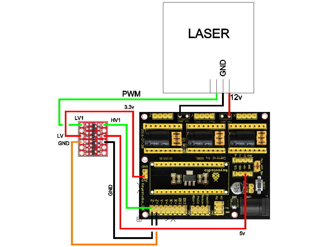
That looks as though it should work to me…
1 Like
Me too, although you don’t need both ground wires going to the level changer board…one will suffice.
2 Likes
Ok, Thanks @dkj4linux & @dart1280. I did think it was odd that keyestudio would put that 3.3v connector so obviously in the way of the usb connection on that nano. I will test this sometime in the next few days, maybe even today.
1 Like
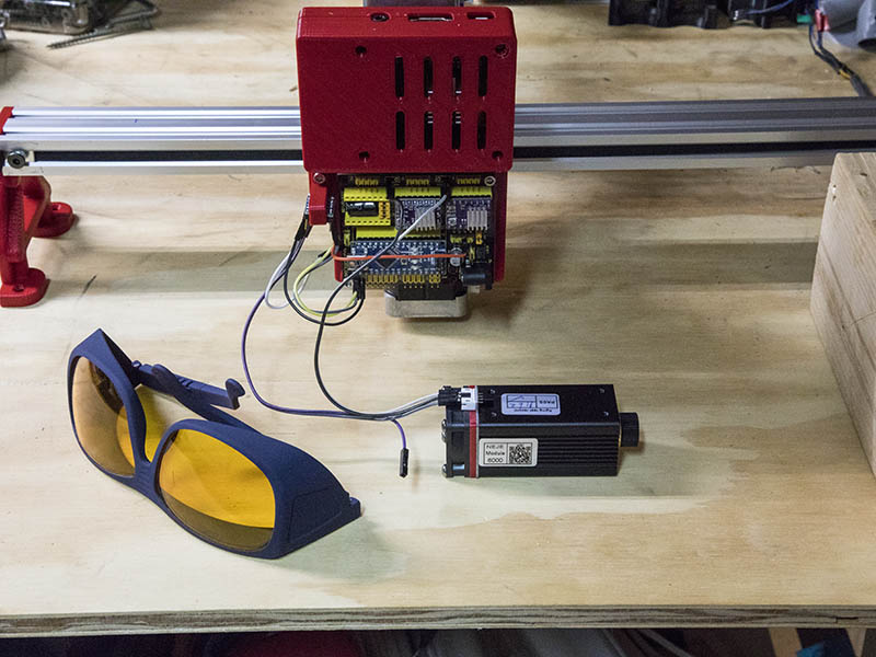
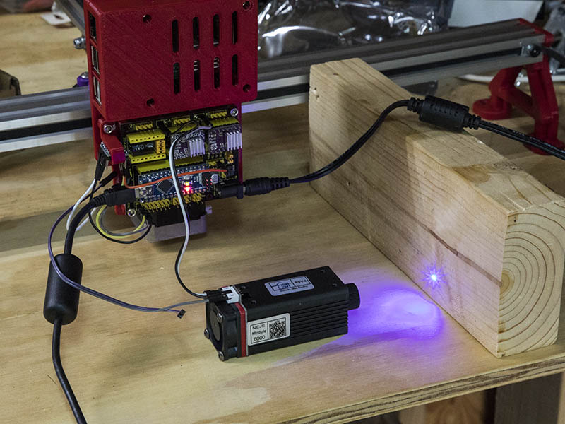
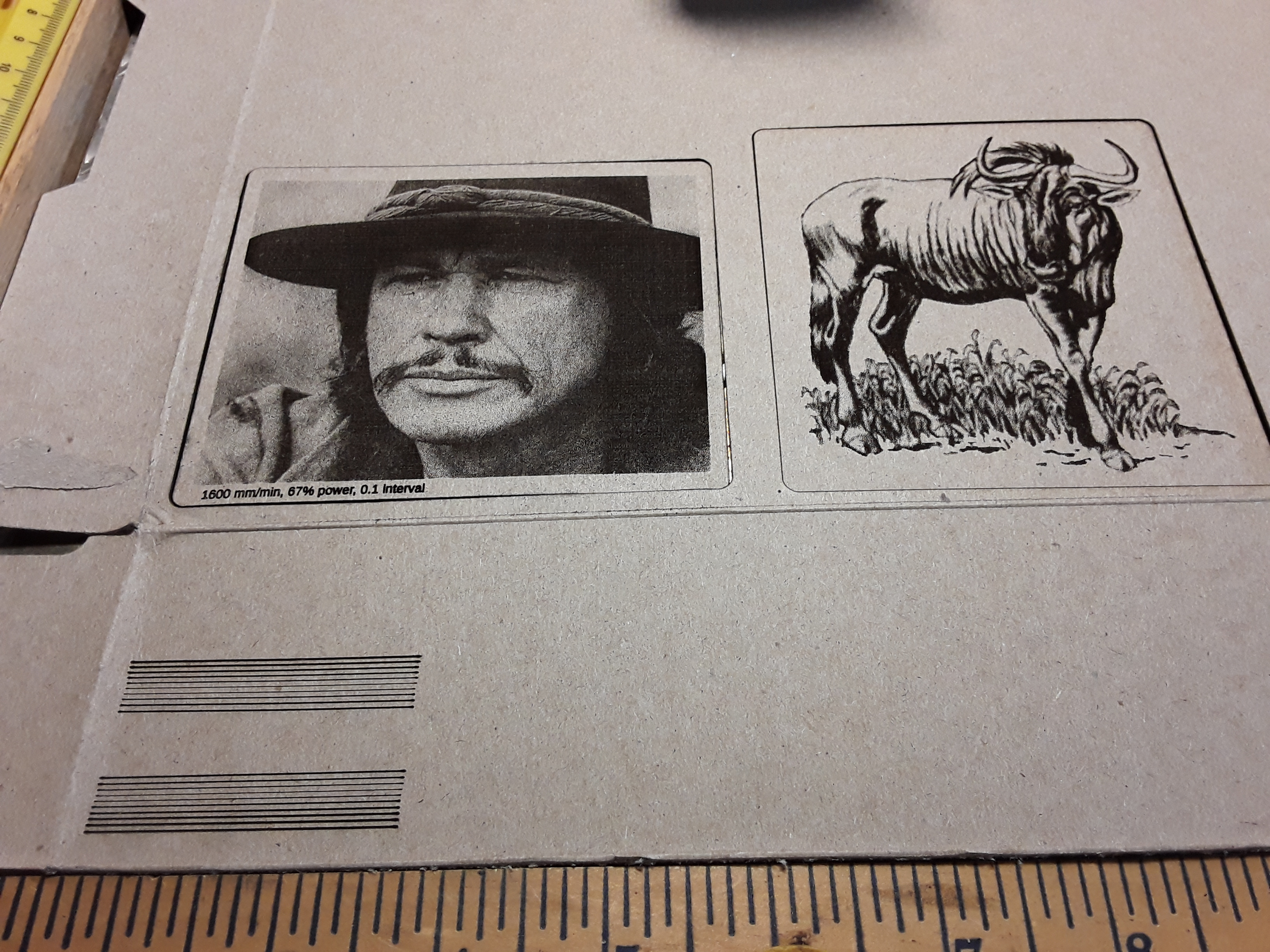
I was able to test it sooner than I thought. Yeah, Both laser work. Initially the 1st laser would not come on except for the fan, but seems to have been a loose connection on laser PWM wire. 2nd laser was really out of focus to start with, but after a few turns of the adjustment knob it looked good. I turned it off between each time I focused it. Laser glasses seem to work well. All I saw was the dot on the wood at M4 S200. I used the openbuilds control software to test it instead of the pi for the 1st run. You can see the black dot on the wood from the 1st laser test. Think I only used M4 S100 for 2nd test.
1 Like
I usually use S2 for framing and focusing…that way you don’t mark the target at all. Glad to hear it all works ok for you. I am always amazed with all the problems people seem to post about when trying to get PWM working with the ‘banggood’ type of laser module with the separate PSU with the two TTL and PWM labelled connectors… it really shouldn’t be that difficult.
1 Like
For the test I was not concerned at making using it low power, but it is good to know what number you use for focusing. I did actually want to burn a dot to make sure it would burn. You can see the 1st burn dot a few inches to the left of current dot. I have pretty good safety glasses & might not be able to see the dot at that low power, but will start with S2 when I do a test burn. You might also notice that I changed the end feet. They are not as wide & are a bit thicker since I was getting a little flex movement in them.
It would be nice to find a laser controller board that had both a 3.3v & 5v PWM option by just changing a jumper. That would certainly make the wiring a lot less trouble.
I offered you a pcb a while ago that has no wiring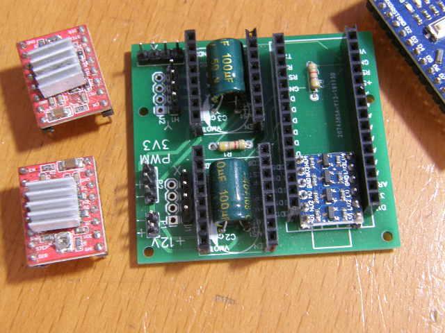
Whilst I didn’t design in a jumper to select the voltage level of the PWM if you wanted 5v for some reason (bearing in mind that any device that is looking for a PWM signal at 5v will work fine on 3v3.) adding a single jumper wire to select LV or HV as the PWM source would be child’s play.
1 Like
I didn’t see the photo with the components populated before & missed that the level converter was actually soldered to the board. That does simplify the wiring. Maybe I should get a couple of those boards from you for future use. I believe you would send one to me for a $1.60. How about if I send you $5 for 2 of them? You can PM me your paypal email or whatever way you want the funds.
Thanks.
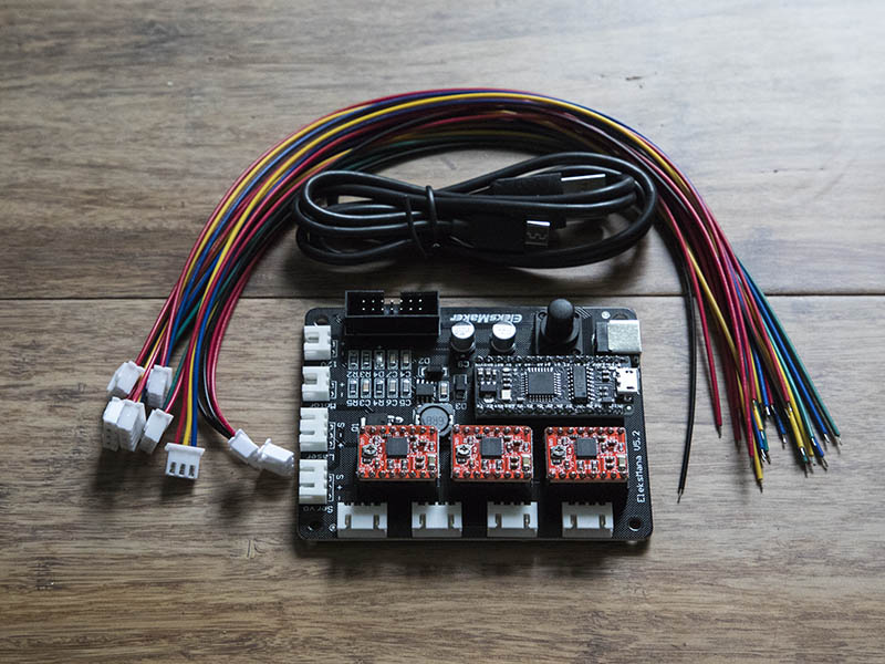
I receive a couple parts in this week. The EleksMaker Mana 3 Axis Controller Board arrived. It was $26.46 total from Aliexpress with the parts in the photo. That is a nice looking board. I also ordered a few things from Zyltech last weekend since they had a 20% off labor day sale. I got a 2040x600mm length V-Groove which should give me about 20" working area along the 2040 axis.
http://www.zyltech.com/zyltech-2040-v-groove-extrusion-pre-cut-lengths-300mm-2000mm/
Since I had one of the 0.9 step angle motors, thought I would get another & use these on the laser engraver & see if the 0.9 degrees makes any difference. These are 40mm in height which is a little shorter than the 44mm thick one I currently have on there which gives me a little more ground clearance.
https://www.zyltech.com/high-accuracy-0-9-step-angle-nema-17-stepper-motor-1-5-a-0-42-nm-59-ozin/
They also now carry eccentric nuts & wheels, so I ordered 4 eccentrics since I did not have any spares now.
http://www.zyltech.com/6mm-eccentric-nut-spacer-for-extrusion-carriage-wheels/
Here is a link to the wheels.
http://www.zyltech.com/zyltech-20-series-wheel-pulley-bearing-for-2020-aluminum-extrusion-v-slot-compatible/
Also @dart1280 was nice enough to send me the gerber files for his board & a link to his design, so I ordered 5 of those boards from https://jlcpcb.com/ which was less than $8 total for the boards. @dkj4linux, I would be happy to send you one of these boards for no cost when I receive them if you would like to try it since I don’t need that many boards. I might play with adding a Z-axis and a couple of other features & order another set if it looks good to me. Is there another good chipset to use instead of the nano that would work with grbl & be more friendly to the CNC.js program?
1 Like
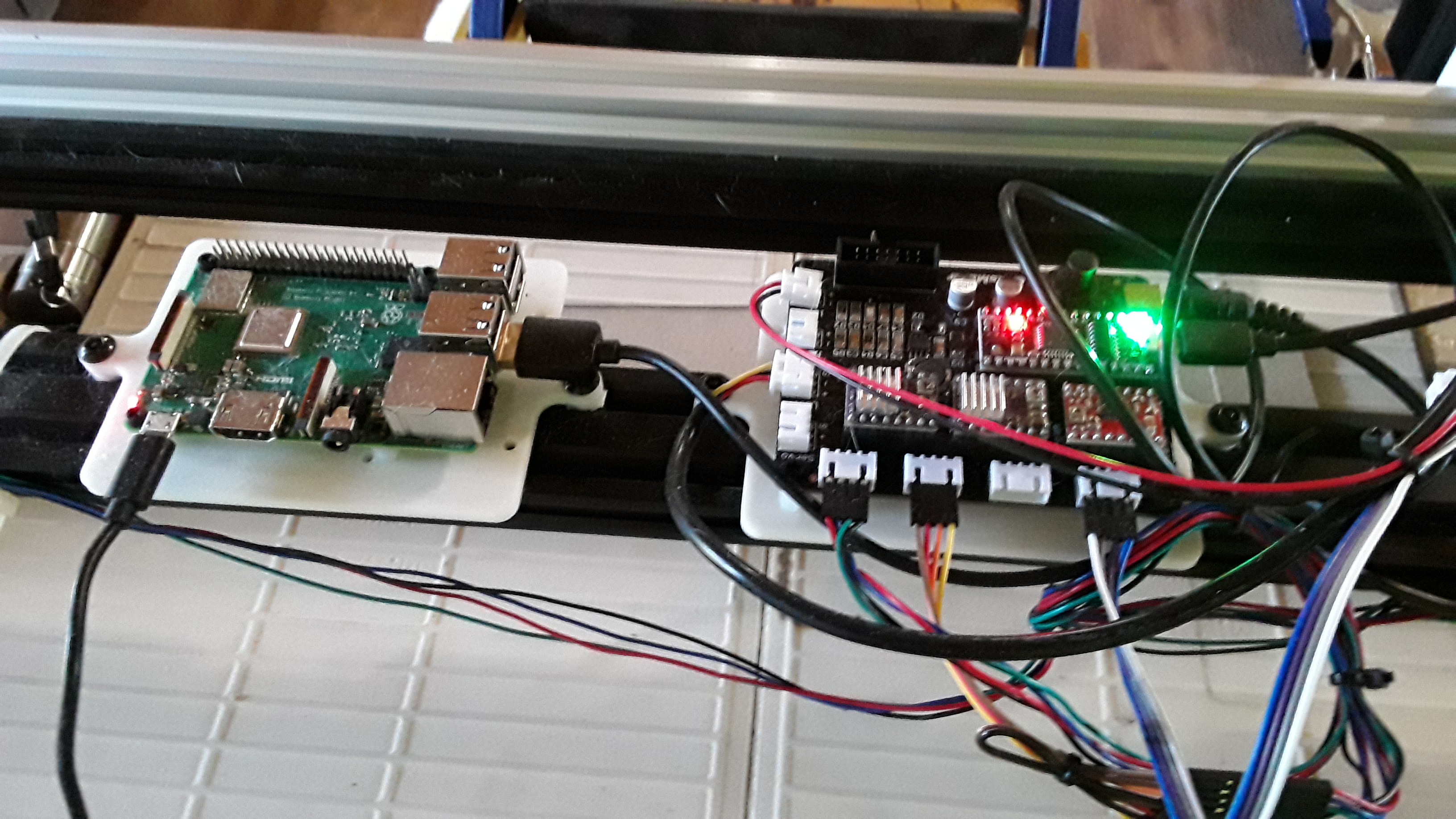
Thanks, Dave, for the board offer but now that I’m confident I can use the 5V PWM output to drive the Neje laser modules, I’m good. And I really feel I “need” the Z-axis most of the time so that Eleksmaker board suits me just fine. I’m really not sure what you’re saying about “being friendly to the CNC.js program”… I use all my boards with CNC.js almost exclusively and without issue. Here is the Pi/v1pi and Eleksmaker boards currently riding on my rolling gantry…
<What follows is my justification for a Z-axis – skip if you’re not interested…>
First, focusing becomes dead simple with Ryan’s focus script. I use it when I’m unsure of how thick the last material I used… and the line gradients allow setting Z for the best focus – or amount of defocus – desired.
And, as you probably know… I love Lightburn. And though I only use it as a gcode generator… being a machine controller as well, it has Z capability; i.e. so I can put Z-adjustment commands into the gcode file.
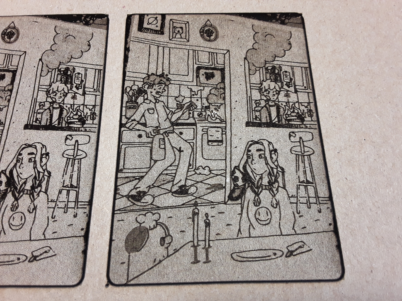
On my grand-daughter’s kitchen sketch, maybe 8" x 10" in size… I “lost” a lot of line thickness when I shrunk it down to a smaller size. So, I center-line traced the sketch in Inkscape 1.0 (a new feature) and kept it overlaying the original image. Importing to Lightburn and resizing as desired, I was able to defocus the traced lines layer by adjusting Z by 5mm, to thicken the lines, and then adjust back 5mm to best focus to raster engrave the image layer… all in the same gcode file.
Here’s the result without center-line trace…
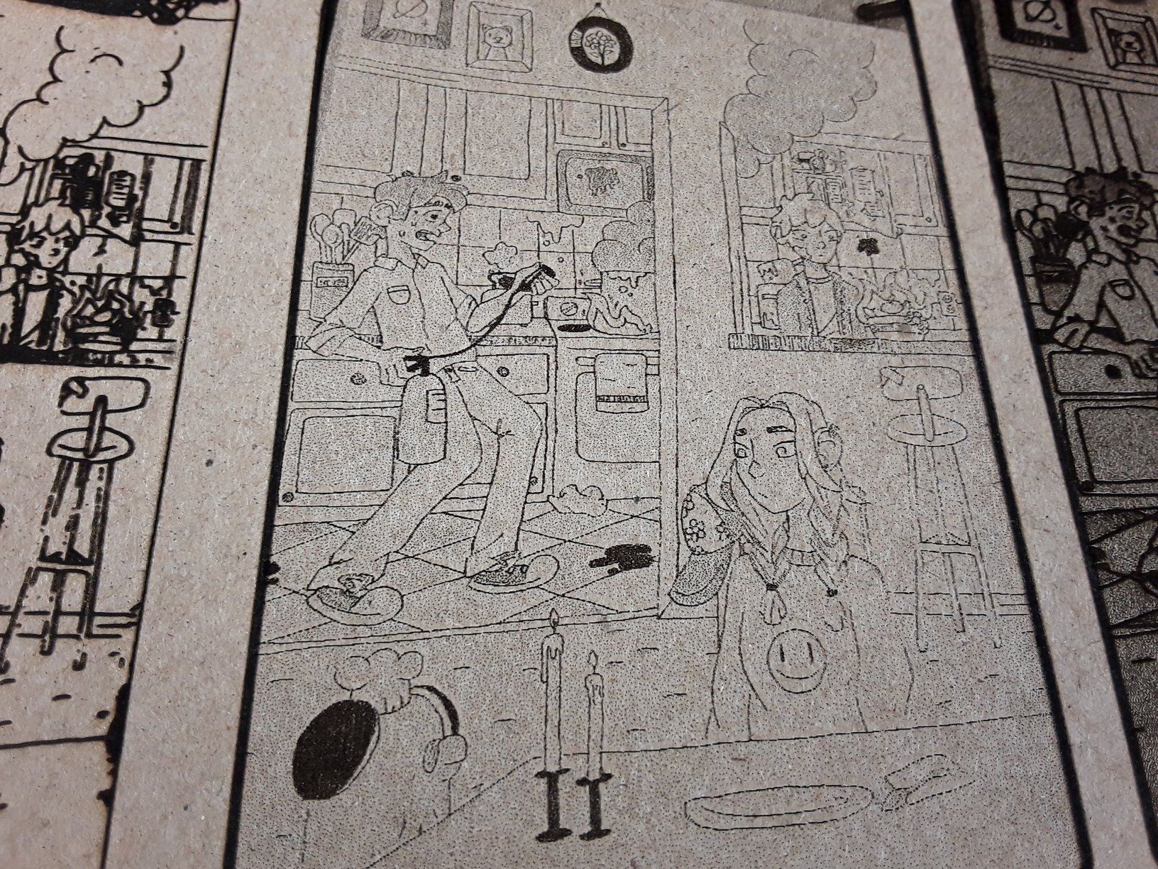
and with defocused center-line trace…
Finally, though I rarely use it, the Z-axis adjustment is there for those multi-pass cutting jobs, where on successive passes the focus point is lowered slightly further into the material. Some folks believe this to be the best way to cut through a material. I’m not totally convinced… but it’s there if you need it. It’s one of those “better to have it and not need it… than need it and not have it” things…
– David
4 Likes