I received my two 6W lasers yesterday & need some help with the wiring. It only took 2.5 weeks to get here from China. I still have to wait for the 3.3v-5v shifters & safety glasses before testing it, but in the meanwhile thought I would see if I can get the wiring straight before then. The color coding on the wire they sent would lead me to think their webpage is wrong, but they might not follow standard wiring colors of red for + & black for ground. My wife pointed out something about the Chinese that I had not heard before which might be why somethings are backwards to us. Traditional Chinese text is read in columns Vertically from Right to Left. Here is the Wiki page on that.
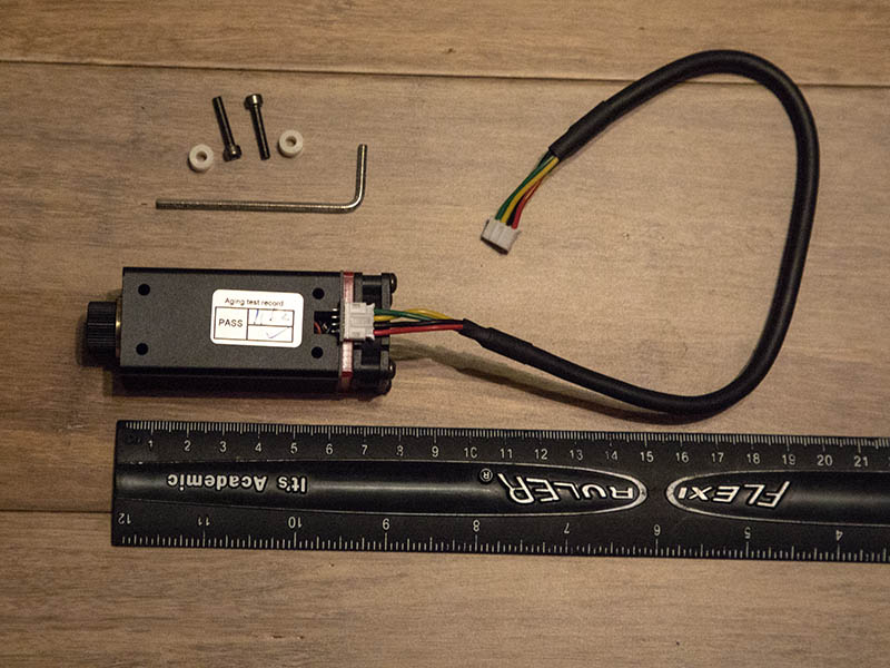
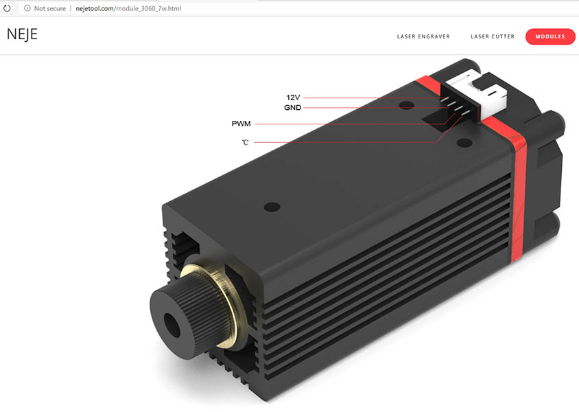
Here is a photo of the laser & parts I received showing the red & black wire on opposite side of connection as they show 12v & Ground on their website page.
Since @dart1280 has used this laser or @dkj4linux might be able to confirm what the wiring is for this.
Also, does the temperature lead get hooked up to anything? Looking at Mike’s circuit diagram from his build page, looks like it is not hooked up.
On my NEJE lasers the picture of the module with the cable connected is correct and the picture with the 12v,gnd,pwm&C legend is wrong…go with the cable!
If you look on the underside of the PCB where the connector is soldered there is a silkscreen legend that is correct…well…mine did anyway!
I didn’t use the temperature facility so just left the green wire disconnected…too much trouble to interface and calibrate some form of display for me to bother with.
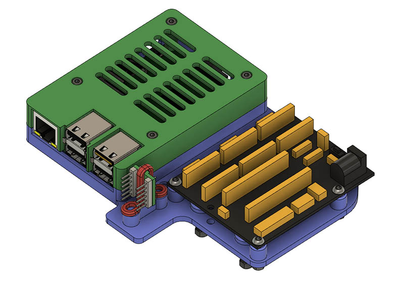
Does that level converter get hot at all? I came up with this idea for mounting that converter, but if it gets hot probably not a good way to mount it.
Okay, I’m joining Mike and Dave’s Neje party. I still have the 6W Neje laser (I was afraid to touch it during the static electricity attack…) that I received when I also ordered that 20W (not Neje) engraver machine… but [you just can’t have too many lasers…] there was another AliExpress sale – and I had already ordered those set-of-10 Ebay level converters – so I had to order yet a second [hey! Dave has two of them…] 6W laser for ~$45. So, now I am committed (I probably should be…) to finally getting one of these lasers set up. And Mike has recommended them…
I’m confident, with Mike and Dave’s help, that this may become my new “standard” laser… it’s substantially cheaper (and more powerful?) than the Banggood/Eleksmaker units I have been ordering [on sale] and using. As MIke and Dave have noted, however, there is still a bit of confusion (at least, on my part!) regards the actual PWM level (3v3 works… what about 5V?) and the connector pin order… but hopefully, once it’s all sorted and confirmed, it’ll be a trustworthy unit for all of us.
This photo should clarify what @dart1280 was talking about with the underside of PCB showing the wiring 12v,gnd,pwm&C. To give you an idea of the small size of this laser, it is 4oz and main body is 74mmx30mm.
I am still unsure of what pin on the keyestudio board to hook up the HV1 5v PWM connection. Looks like from @dart1280 schematic he shows it going to the D11 pin on the Nano board, but he is also using a custom board for this. I am referencing @dart1280 schematic for HV1 connection. Rather than solder the pin headers that came with level converter, I might just solder the jumper wires to it. If I mess up, I have plenty of spare level converters. Here is a link to @dart1280 schematic. https://www.modelflying.co.uk/sites/3/images/member_albums/182214/845754.jpg
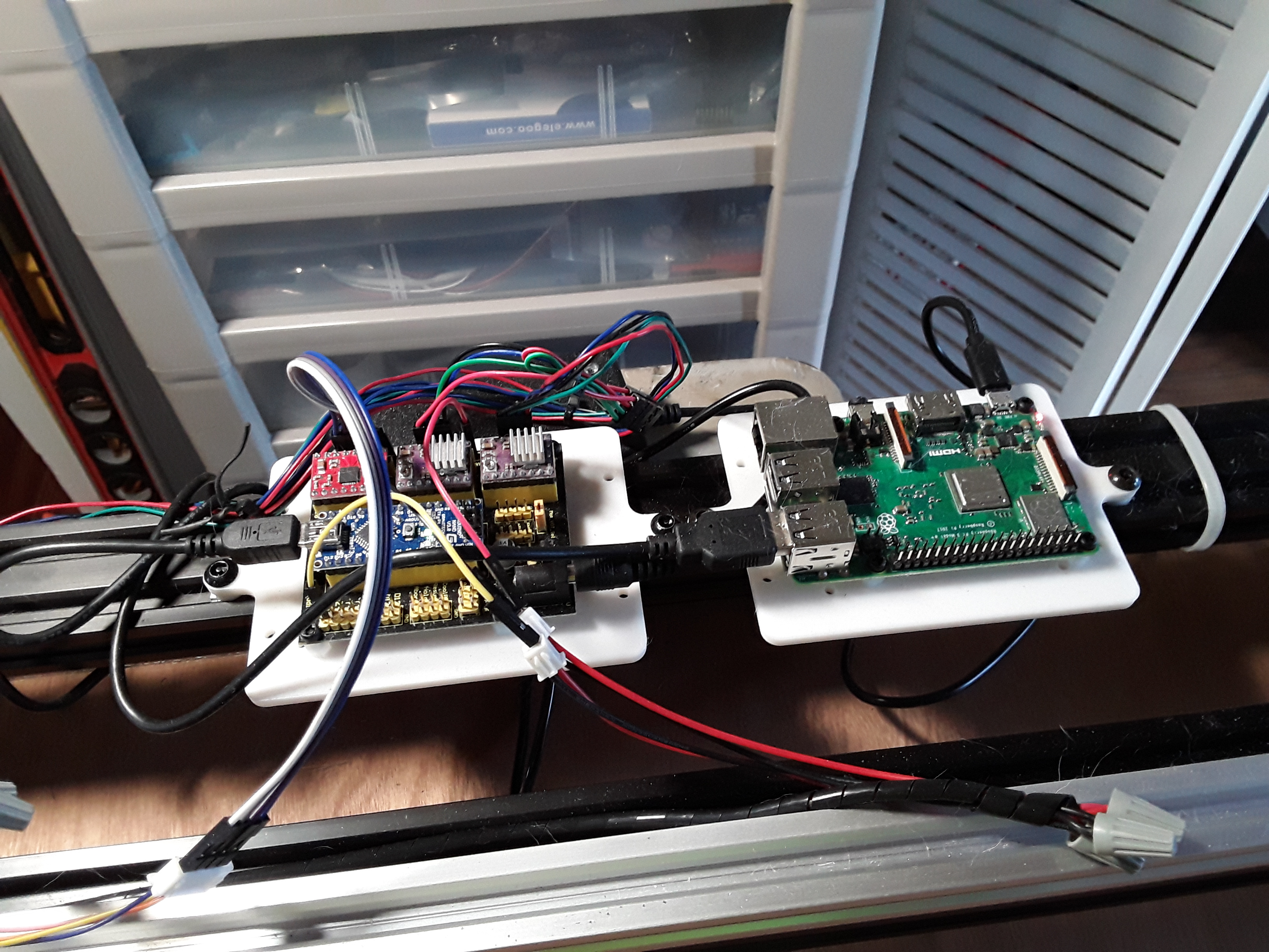
Note the three jumper wires connected to the controller in the foreground… red is +12v, black is ground, and yellow is the PWM connected to “Z-” pin. Z- is indeed the Nano’s D11 signal and works properly to modulate the laser using M3/M4/M5 gcodes in Grbl. The only reason I swapped out the controller board on my machine is that the Eleksmaker board I put in had the proper 3-pin connector for the 3-wire cable supplied with the laser I was using… didn’t have the kluge-wiring shown here.
Thanks, that should cover my wiring problems unless something else comes up. I did go ahead & order one of the eleksmaker boards & may use that. Someone in your other thread had a problem with the keyestudio board messing up his laser & after all this talk of 3.3v PWM, I am wondering if that was his problem.
I am not sure 5v PWM would hurt the laser and the quoted ‘TTL’ would actually mean it is meant to run at 5v as TransistorTransistorLogic was a semiconductor gate spec that utilised signal voltages of 0v and 5v for the on/off logic levels…but would you trust the Chinese to get that right?..I wouldn’t! The level shifters are very cheap and Bart Dring uses one (not the same unit but a surface mount 3-5 shifter) in his ESP32GRBL boards so if it’s good enough for him…
I actually lived and breathed through the TTL era as an engineer responsible for circuit design in the defense industry… and, to me, TTL speaks to the digital logic levels involved, i.e. input levels of <= 0.8V is low and >=2.0v is high. So, while TTL devices did indeed run on +5V power, the logic levels were not rail-to-rail levels. That’s the “old school” definition. I doubt there are many modern designs that still use true TTL logic levels.
Today, “TTL” most often seems to mean 0v to +5v logic as far as I can tell… but is this always the case? I doubt it. It seems to me there’s so much confusion on the part of a lot of folks – maybe even the vendors – regarding what “TTL” is and what “PWM” is… so I’m still not 100% sure of what I’m getting, even when they try to quote the “spec” to me.
IIRC it used to be TTL vs. CMOS. TTL likely needed more current to drive being BJT transistor based. CMOS needed current only during switching being MOSFET based. That’s why the TTL designation was important, you needed to know how to drive the chip you were talking to. That’s all history I don’t think we need to care about here. My cheapo banggood “TTL” laser seems to work fine with my SKR Pro board’s 3.3V PWM outputs (with a physical 2.2K pulldown resistor added, without which it blasts at full power), though others could certainly be different.
True TTL devices were pretty power hungry… as, internally, they were comprised of bipolar transistors, up to SSI/MSI levels. After TTL, CMOS devices came on the scene… and if you choose to run it on +5v power, it looks and “acts” like pretty much like TTL, except the logic levels are near rail-to-rail logic levels. I haven’t looked but I’d assume Arduino devices and similar – with 5v i/o pins – are probably some type of CMOS on the inside.
This +5v digital logic stuff has been around a very long time now (50+ years). Given it’s low-cost, ready availability, “cookbook” nature (digital vs. analog), and low-voltage, ease of use, popularity – with hobbyists and even “non-engineering” types – many folks who use it might even call it “TTL” – since it’s digital and runs on +5 volts – but it is definitely not the same stuff.
Don’t the banggood lasers need that pulldown to prevent the laser firing up at full power during boot as the pwm pin is left floating? I believe it is a feature of the nano/uno architecture…that’s why I fit the pulldown on my boards, Maybe the output pwm signal from the arduino is 5v and off and not 5v and gnd?..that would certainly fit your description of the laser being on all the time without the pulldown.
Absolutely needed for startup safety and even general operation after boot, at least on my SKR Pro board. The PWM output pin I’m using basically comes straight out of the microcontroller (no buffer) and it can’t pull the pin down enough on it’s own without the 2.2K pulldown. I first tried 22K and that was too big. Maybe there’s a different mode the pin could be put in, but it’s needed for bootup anyway. I put it on the laser itself.
It’s my understanding that the laser firing (or spindle blip) during Arduino bootup is because the same PWM pin used for speed/intensity control is programmed to flash a diagnostic LED during the board startup process. I read somewhere you could flash a different boot loader and the behavior “should” go away. Didn’t sound to me like they’d tested it themselves.
I keep the laser enable and/or spindle power switches turned off until I know I want to start a job, but I know that doesn’t really qualify as a fail safe situation.
I keep the laser enable and/or spindle power switches turned off until I know I want to start a job, but I know that doesn’t really qualify as a fail safe situation.
It relies on me to remember to turn stuff off after the previous job, so I don’t consider it automatically failed-safe.
Healthy respect for the destructive capacity of industrial machines has helped me keep all 10 fingers and both eyes. I wish I’d started wearing hearing protection earlier. Not much hair left, but I can’t in good conscience blame that on machinery.

