Yeah I was afraid of that. What if the pegs had a live hinge at the base of them? Not sure how that would be modeled to print easily and it wouldn’t stand up to much use but then then could fold out of the way when you pull them out of the clamp grooves. Probably more work than its worth.
Or threaded posts could work and then you just unscrew them and flip the clamp bit around and then thread them back in again. That way you could actually have different length bits the posts thread into so they don’t stick out so far.
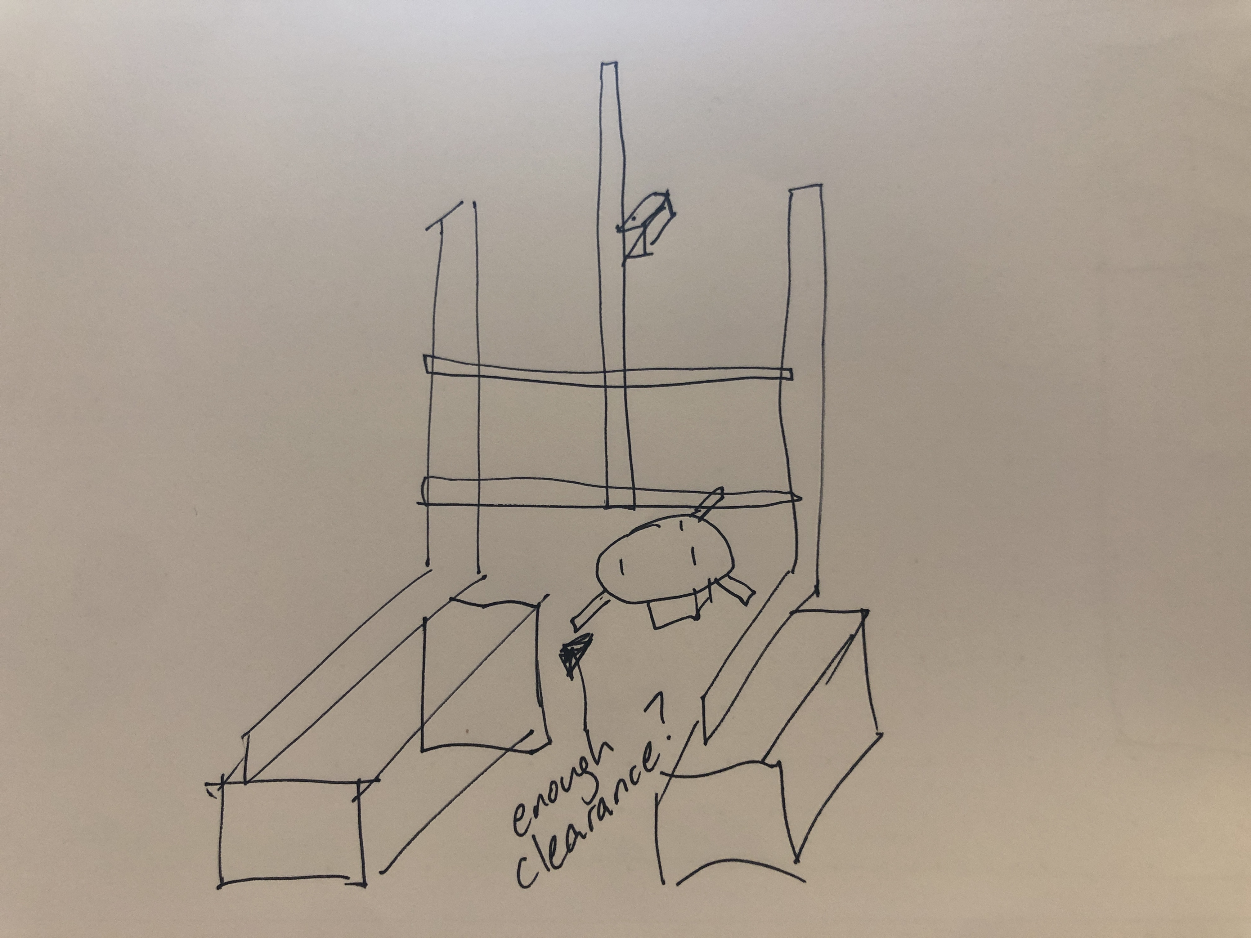
I’m thinking the bad part of them sticking out so far is that they will hit the vertical rails of the laser support. If that’s the case, what if you put the gantry on top of something so that the aluminum rails are higher than the clamp bits that stick out. Then they may not be as big of a deal.
Clearance was my main concern, but with the z-axis 2020 & the machine being more rigid it might not be a concern. I am tired of looking at this turntable design for now & will put it aside until I or someone else gets a better idea for it.
What if you made the top plate solid with just straight slides for the pegs, and put springs behind the sliders? That way you don’t need set screws for the sliders, and you can just put a plug in the ends as a stop, and they won’t stick out. This also will auto-center the workpiece.
What about using gears to keep them mostly aligned? You don’t really need to keep force on the mug do you? It’s really just that you want the pegs to stay equidistant from the center of the platform.
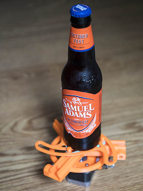
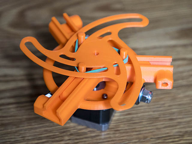
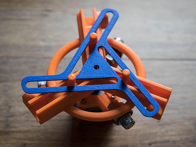
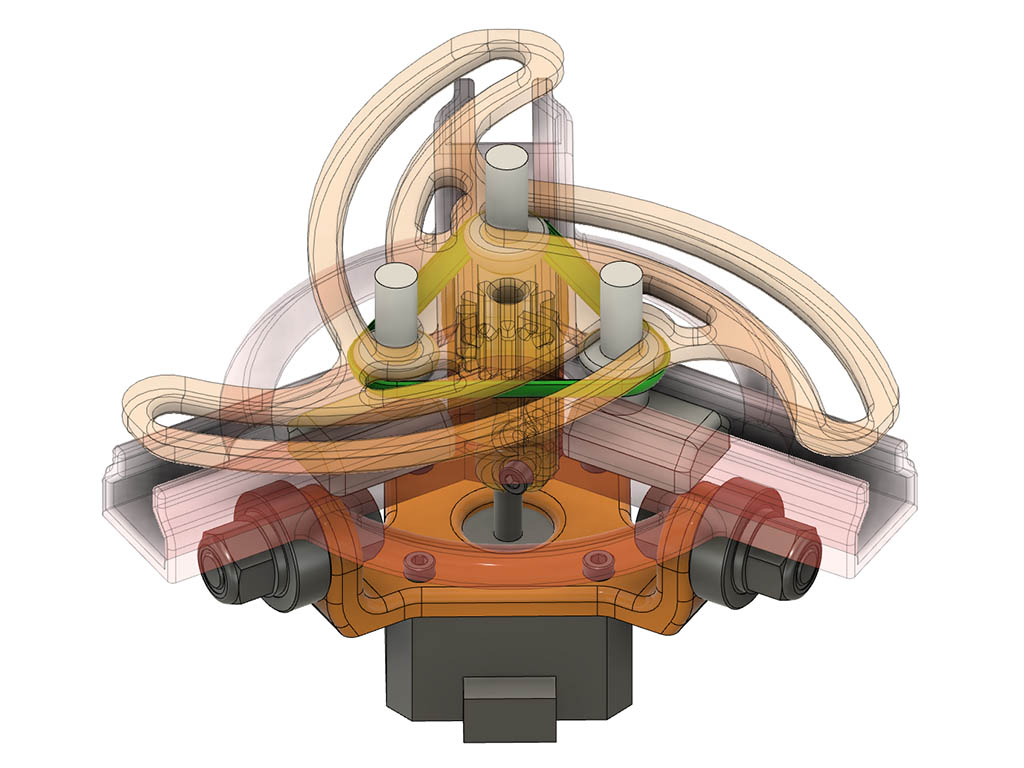
I like the spring idea, but then you made me think about using rubber bands. Thanks for triggering the light bulb in my head. They are a perfect simple solution with no other electronics needed. I will have to adjust the sliders a little to give a little lip under the pegs & make the pegs probably a little longer. Here are a couple of photos to show proof of concept. Just when I am ready to put this project aside, ya’ll pull me back to finish it.
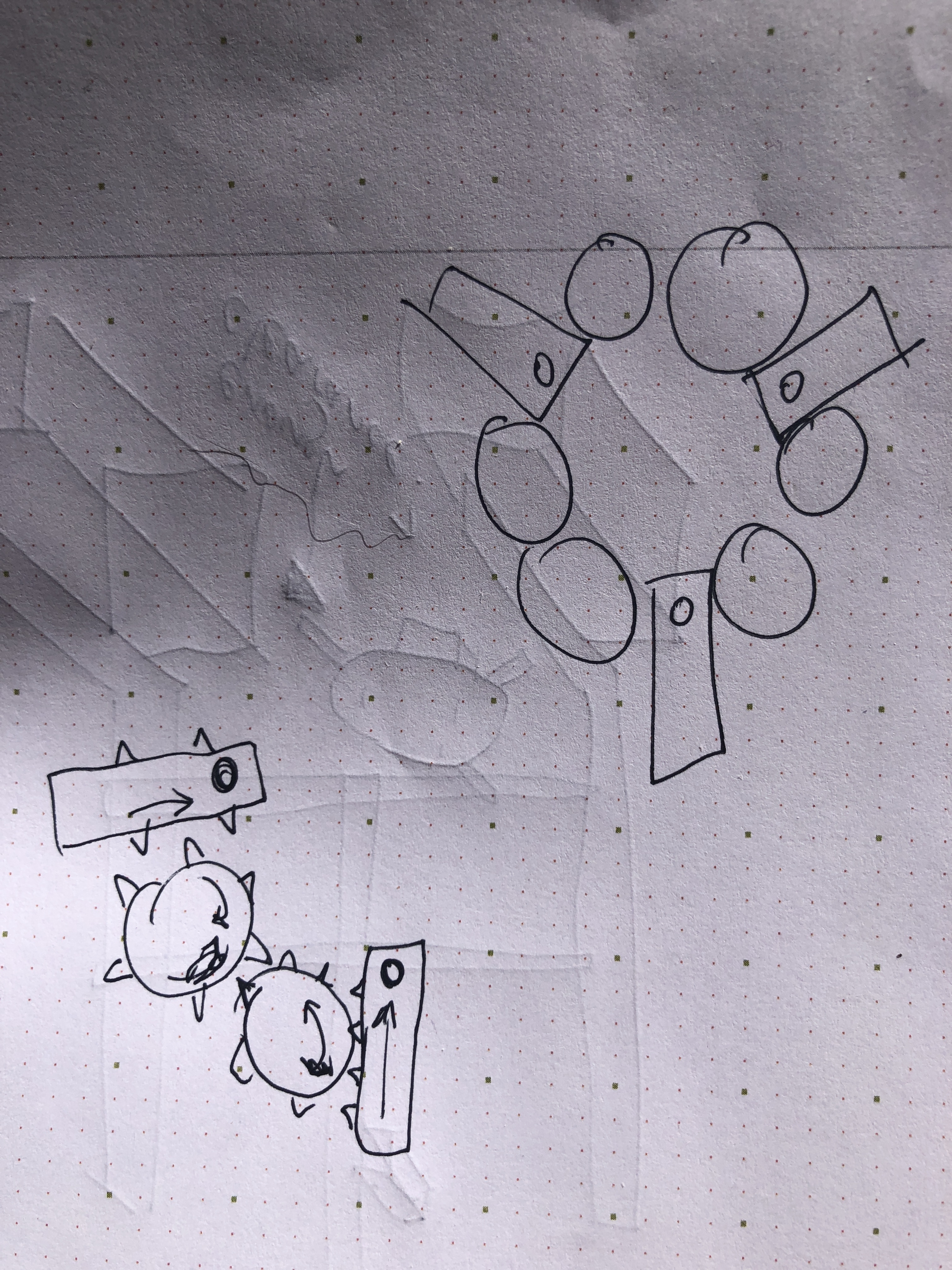
I had to try the straight slots to see what the problems were with them versus the curved slots. During the design, one problem that is quite apparent is the end of the slots are a lot closer to the sides of the other slot next to it. They also don’t move well along the straight lines as they do along the curve. I am printing the new design today & maybe try it tomorrow.
Here is the 1st test of the self centering rotary axis. Seems like this painters tape core has a coating that does not burn well in some spots. It also seems like the rotary axis is moving faster than the linear axis. I posted a message to lightburn forum about it, but maybe someone here also knows what the problem might be.
In the rotary section of Lightburn, I have 32 mm per rotation (DRV8825 drivers) and Chuck rotary type set. Y-axis is the rotary axis & X-axis is the vertical linear axis in my current configuration.
Below are the GRBL settings I am currently using in this configuration.
Grbl 1.1h [‘$’ for help]
$0=10 ;Step pulse time, microseconds
$1=255 ;Step idle delay, milliseconds
$2=0 ;Step pulse invert, mask
$3=3 ;Step direction invert, mask (invert x & y)
$4=0 ;Invert step enable pin, boolean
$5=0 ;Invert limit pins, boolean
$6=0 ;Invert probe pin, boolean
$10=1 ;Status report options, mask
$11=0.010 ;Junction deviation, millimeters
$12=0.002 ;Arc tolerance, millimeters
$13=0 ;Report in inches, boolean
$20=0 ;Soft limits enable, boolean
$21=0 ;Hard limits enable, boolean
$22=0 ;Homing cycle enable, boolean
$23=0 ;Homing direction invert, mask
$24=25.000 ;Homing locate feed rate, mm/min
$25=500.000 ;Homing search seek rate, mm/min
$26=250 ;Homing switch debounce delay, milliseconds
$27=1.000 ;Homing switch pull-off distance, millimeters
$30=1000 ;Maximum spindle speed, RPM
$31=0 ;Minimum spindle speed, RPM
$32=1 ;Laser-mode enable, boolean
$100=160.000 ;X-axis steps per millimeter
$101=200.000 ;Y-axis steps per millimeter (200 * 32 = 6,400 rotates 1 revolution with 1.8 nema17)
$102=200.000 ;Z-axis steps per millimeter
$110=500.000 ;X-axis maximum rate, mm/min
$111=500.000 ;Y-axis maximum rate, mm/min
$112=500.000 ;Z-axis maximum rate, mm/min
$120=100.000 ;X-axis acceleration, mm/sec^2
$121=100.000 ;Y-axis acceleration, mm/sec^2
$122=10.000 ;Z-axis acceleration, mm/sec^2
$130=435.000 ;X-axis maximum travel, millimeters
$131=435.000 ;Y-axis maximum travel, millimeters
$132=0.000 ;Z-axis maximum travel, millimeters
I wonder if the rotary axis speed should have something to do with the radius of the thing you’re etching. If the rotary axis was spinning the same speed and you had something with a smaller radius then a point on the surface of that smaller item would move less distance than something with a bigger radius.
I just checked the video time between running the 45mm vertical & the 258.4mm around the circumference. It took 5.14seconds for the 45mm vertical line & 4.045 seconds for the 258m.4 length. Using a spreadsheet, that distance around circumference is 5.742 times further. If I went vertical for the same distance with current setup, it would take 29.515 seconds. I think it is going 7.296 times faster around the circumference. Does that make sense? I had the speed for the burns set to 600mm/min. Maybe I have $110 & $111 set to low. I use to have those set to 3000, but lowered them when the rotary was turning too fast. I will have to run these at 500mm/min tomorrow & see if that changes anything.
With the original EggBot, the approach was to define the rotary axis as taking 3200 steps (1.8 degree steppers using 16x microstepping) and designing the artwork in Inkscape to be 3200 pixels wide. No need to correct for different circumferences, but can be a bit fiddly to bring in existing artwork.
I’d think that was a different situation though since you were probably using a pen to draw on the eggs which would be more forgiving than getting a consistent laser/etching depth. The laser isn’t going to work as well if the axis rotation is faster than the vertical movement speed.
After some trial and error today, I have it pretty darn close by watching the video test I shot & checked frame by frame near the end of each movement to get the time it took to run a 100mm square in both directions. I switched to using Z-axis since I got that to work, so less firmware settings to change. Since rotational axis was 7.296x faster than linear, I used 200/7.296 = 27.412. Since I am using DRV8825 (200*32=6400) 6400/27.412 = 233.47mm.
I set:
$102=27.412.000 ;Z-axis steps per millimeter
and 233.47mm = mm per rotation in Lightburn rotary setup
It was a little off, but speed difference between linear & rotation seemed close. I wanted to see if I could use whole numbers, so I changed the $102=27 and starting adjusting the mm per rotation until it made one full rotation correctly. It came out to a nice whole number for that also.
$102 =27 and 245 =mm per rotation in Lightburn rotary setup. With those settings, it does one rotation right on the money & speed difference between linear & rotational movements seems correct. I am seeing a little stuttering in the rotary axis, so am thinking that is the DRV8825 doing that . I have several LV8729 drivers that are 1/128 microstepping, so am going to try those on both axis to see if that stuttering disappears.
[Edit] I tried the LV8729 drivers but they did not seem to work properly. Either the Eleksmaker board does not support them or they are bad drivers. I did check the vrefs on them before putting them on and from my previous notes I have the correct voltages. I will just stick with the DRV8825s. After putting the DRV8825s back in I rechecked the rotatary setup & had to change that 245 to243 as it overshot the 360 by a little bit. So my numbers are $102=27 & 243 for lightburn rotary setup.
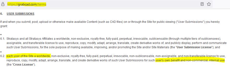
Since this self centering turntable is a derivative of a design I found on grabcad, I am wondering if I can publish it to thingiverse as a non-commercial license.
Is anyone familiar enough with this lingo to tell me whether I can do it or not. Here is info from grabcad’s website concerning the use of the data.
You are probably right, but did not feel like I should. I did realize this morning these sliders are just like the Trammel of Archimedes & I drew one of them up a while back. I will just redraw it based on that design, then I won’t have any problems. The top is not a problem as I drew that based on the longworth clamp construction method. I want to make one with a little bigger diameter anyway. Here is a link to the Trammel of Archimedes I mentioned. Remix of Trammel of Archimedes by GeoDave - Thingiverse
my build is getting close to being done. super excited. Now im just trying to figure out the homing/startup routine …
doing alot of reading but getting confused
how does homing work for lasers? Im used to 3D printers so is it exactly the same minus z ?
do i have to disable z axis homing in config.h for grbl? or can i just leave it alone and just use grbl settings to manage everything?
are $130 & $131 essentially placing hard limits on the size of the lazer working area?
really not sure how the homing routine / end stops work for a laser (with x, y only) … i can move the motors and gantry head fine i just dont know if im moving in the correct direction…
if anyone can point me in the right direction it would be appreciated…