I am not a lawyer, but publishing it with a CC-NC seems like it is in the same spirit. You could always ask the designer. I bet you they won’t care. And as long as it isn’t the next prusa i3, no one will bother.
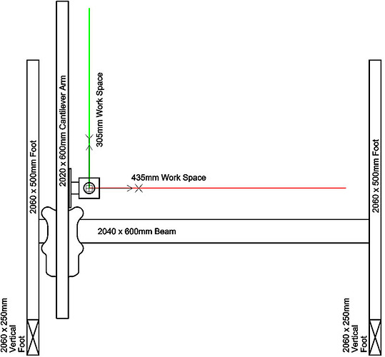
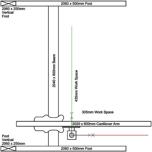
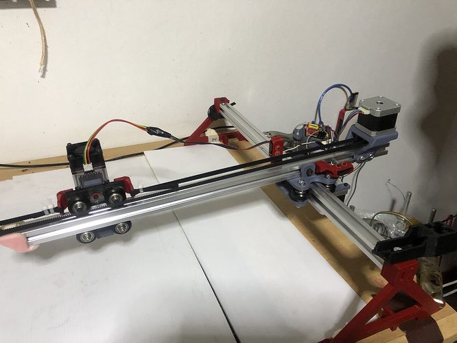
Lets start off with the X & Y layout. Direction of the motors depends 1st on what direction your Main Beam axis is & your Cantilever axis. Using the V-Slot sizes in the below diagram will show the direction your motors should go in the positive direction along the Red Line (X-axis) & the Green Line (Y-axis). Where the Red & Green Lines intersect will be 0,0
If your motors are moving in wrong direction, you can either turn your wires around on the board connection if they are dupont connections or use the grbl settings as shown here:
grbl/settings.md at master · gnea/grbl · GitHub
$3=1 (Invert X direction motor)
$3=2 (Invert Y direction motor)
$3=3 (Invert X & Y direction motor)
If you use the Cantilever arm as your X-axis you might also want to consider rotating your laser gantry carriage to the other side of the cantilever as 0,0 the edge of it might hit the 2060 feet & you might have to change the limit switch brackets. You can see about where the laser is located in the 2 screen shots.
If you are planning to use the rotary turntable at some point you might want to consider this. I am currently using the X-axis along the main beam as I wanted the longer axis to be my X, but since adding the 2nd 2020x600mm back beam, I made my cantilever arm 700mm and am able to get a 435x435mm work area and cantilever seems to be more solid than with the 600mm with the single 2040 beam. The only reason I would start using the cantilever arm as the X-axis is because Lightburn currently does not have a way to use Y-axis for what they call the “scanning axis” in rotary mode & they say they are not likely to add it. Looking at their G-code, it would be easy to make a post processor for this to just substitute G1X to G1Y & G0X to G0Y
Here is a sample of the gcode output using X-axis for scanning axis & the Z-axis for rotary axis.
Looks like they have a minor bug in the Bounds comment when using the Z-axis, since it should be X0 Z0 & X90 Z90. They did tell me they did not know whether Z-axis had actually been tested. It does works for me.
; LightBurn 1.0.02
; GRBL device profile, current position
; Bounds: X0 Y0 to X90 Y90
G00 G17 G40 G21 G54
G91
M4
; Cut @ 600 mm/min, 80% power
M9
G0X18.725Z13.753
; Layer C00
G1X-0.778Z1.134S800F600
G1X-0.742Z1.189
G1X-0.705Z1.242
G1X-0.665Z1.294
G1X-0.625Z1.342
…
G1X0.044Z-1.763
M9
G1S0
M5
; return to starting pos
G0 X-89.985Z-70.53
M2
I am currently not using the limit switches on my machine as they would not work well for me with the Eleksmaker board. I am using x,y & z limit switches on my openbuilds Sphinx CNC machine & the only settings I changed were $22 & $23 for homing. I had to invert X & Y homing on that machine, so I had to also change $23.
$22=1 (homing cycle, bool)
You might also have to change
$23 = (homing dir invert mask) Probably only need to change that if you change the $3 direction mask as shown above.
Since you are not using a Z-axis, I believe homing should work mostly like your 3d printer. Someone else might give a better understanding of the limit switches than I can.
Let me know if that clarifies a few things.
Wow… thank you so much @geodave 
I initially posted a message to the author on his design in grabcad, but did not hear from him for a few days. Thinking he did not view that site often, I deleted that post & put a shorter comment on the youtube video with a reference to the video of it running. That comment seemed to have been deleted somehow, so decided to not take that further. I will give him credit in my description when I post it to thingiverse. I also plan to make it a non-commercial license. I redrew the design yesterday using the trammel of Archimedes as a guide that I mentioned earlier which helped to simplify the design a little more. I cut out another 20% volume in the design & seems like it will work just as well. I made 2 size versions this time & will print the bigger one, since I have an object that needs a bigger top. My printer jammed a couple of days ago & think I fixed it yesterday. That is the 1st time it has jammed in a long time. If the printer cooperates, should get the new version printed today.
You are welcome. That info had not been explained well before in this thread, so thought others could also benefit from it. One other thing to consider if you move the laser carriage to opposite side of 2020 cantilever is to rotate the motor mount 180 degrees since the belt path is offset from center. The belt path offset was needed to miss the wheel locknuts. If you are concerned which side your wires are attached to motor, you can rotate the motor for the best wire management. Looks like the idler mount STL file would need to be mirrored also. Maybe I will make a mirrored version of each of those parts.
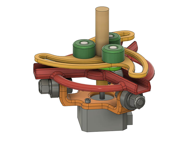
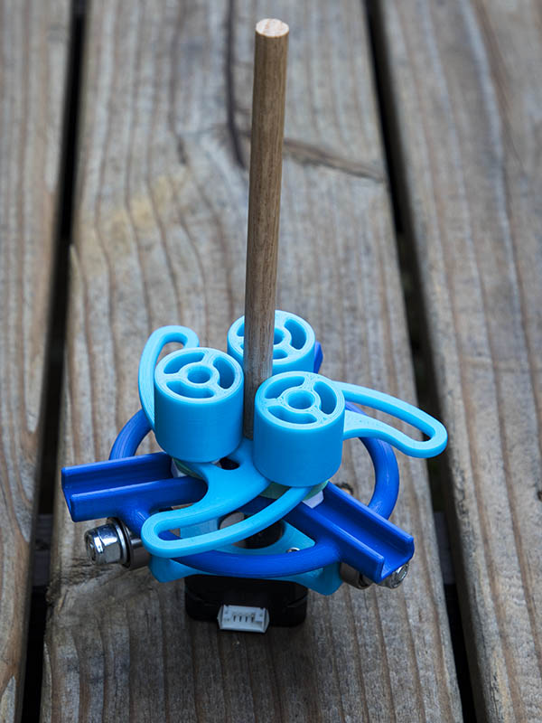
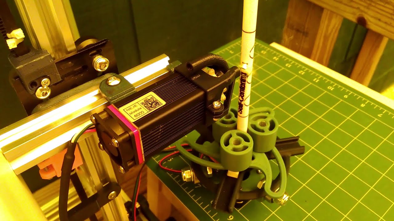
I am getting very close to releasing this, probably tomorrow. One problem I was running into was smaller objects less than about 1" in diameter, which probably is not used much. Dowels are a good example of that small a diameter & that would be a good test burn. The bracket attaching the top to the motor would interfere with making those pegs get closer to the center. So what did I need, Spacers inserted over the pegs. Another simple solution. Here is what the final design will probably look like. I estimate $15-$20 in parts and almost no cost if you have the motor & bearings.
3/8" dowel. There are some pen turners on openbuilds that have been looking for a way to laser etch their pens. With the spacers, this can go down to about 5mm diameter. Here is a 3/8" oak dowel attached.
You could hold a toothpick, if you had a toothpick to 5mm adapter. But you probably don’t need to etch toothpicks.
Though, if you can, that would be neat to see!
so i was able to finish the build, got homing to work and laser fires but im just now realizing that using 2020 for X axis was a really really bad idea…lol… I Shouldda stuck with your original build plans but i have so much 2020 thats just laying around collecting dust. Either way its clearly not going to work.
So im gonna buy some 2040 and 2060 but i noticed @geodave that a new design you made uses 2 x 2020 for the X axis vs 1 2040… Based on the photos you uploaded the 2X 2020 looks really stable and beefy…but not sure. …based on your testing which one do you like more? ie more rigid / stable?
Im only planning on using the laser in horizontal (regular) not vertical…not sure if that matters.
I can go either way at this point and the cost will be about the same for either option… cheers
Now you can inscribe all your pens and pencils. I hate when people steal mine and later claim that it was there’s in the first place. 
Jokes aside, your designs are really cool and inspiring.
I just looked at the toothpicks I have & they are 2mm in diameter. I will have to try that. My laser beam is about .5mm diameter, so it should work. Nice thing about these objects is it does not take long to run a burn on them. Round chopsticks or kabob skewers would also be fun.
There was someone where I used to work that wrote MINE on all his pencils. Of course if the pencil showed up on someone else’s desk, they could say it was mine.
I am not an engineer, but since the double 2020’s are spread apart just as much as my 2040 & 2020 should be about the same. I did not have an extra 2020 the same length or I would have tried it. I used that engraver with the plastic feet for a while & it will work. The V-Slot for the legs does make it more rigid and balanced. While you are ordering the 2060, you really should consider getting 2 - 2060x250mm & 2 - 2060-500mm & brackets to be able to make horizontal or vertical since it opens up some more possibilities for engraving. What laser & controller do you have on your machine?
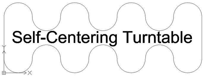
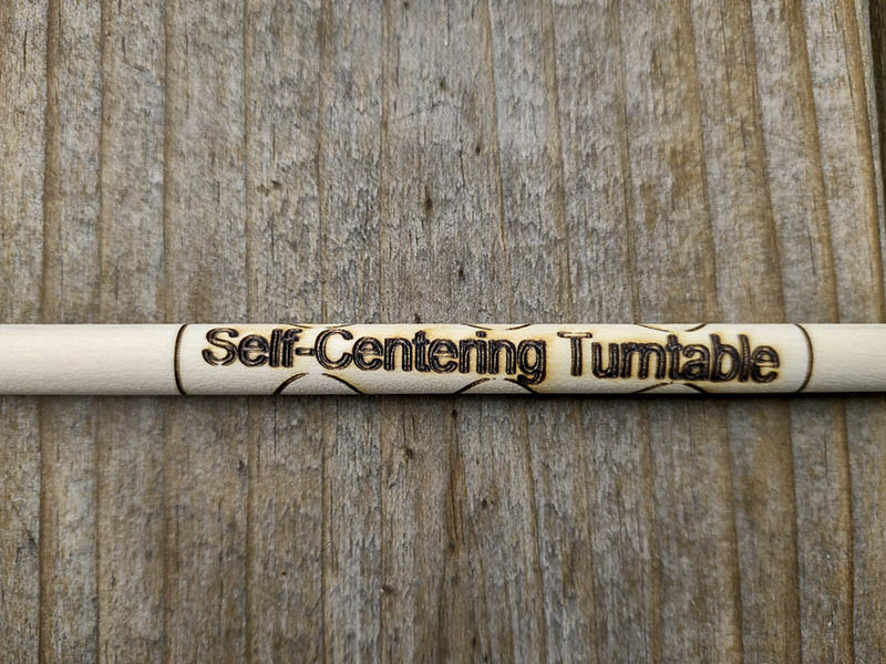
Here is a 3/8" dowel burn running at 3000 mm/Min & 90% power. 1st image is what the design looks like. I wanted it to wrap all the way around to see how close it came to meeting other side.
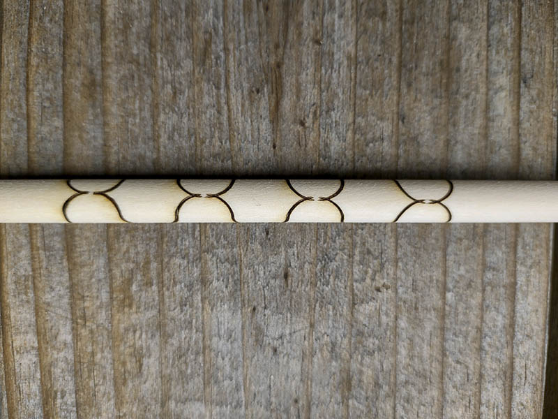
Came out good for a 1st test, but is not quite aligned with length of dowel. This dowel was quite straight, so probably dowel was not quite parallel with the cantilever arm.
You can see a slight overlap here. Measuring with digital caliper, it is about .65mm overlap.
I see a pile of burnt-in-half toothpicks in your future 
It could be the dowel not centered, or the lasers acis not parallel to the dowel (not trammed). Can you use the laser at some small power, like 2% to check the top is as aligned with the laser as the bottom?
I could see that kind of error easily happen if the whole thing was on a tile floor or something. The rotation axis would be off from the base of the laser.
Now that I think about it more, if the dowel was off center, the pattern would get smushed and stretched as it rotated. It might be too subtle to see though. My guess is the axis isn’t aligned.
Also, that is awesome.
I did this on the back deck with the turntable on a foot stool & the engraver sitting on the deck, but I didn’t check it carefully for being trammed to the cantilever axis. I visually checked the dowel for being perpendicular, but didn’t scrutinize it. Next time I will check it more & do a 2% check at bottom & top. Definitely have to be more careful when I try a toothpick.
I have the self-centering turntable design published on thingiverse now. Self-Centering Turntable for use with Vertical Laser Engraver by GeoDave - Thingiverse
You maybe right about the burned in half toothpicks. Think I had power too much on this dowel & saw flames occasionally
