Here is a short video of the testing of this table. I might need a better way to center object on turntable. I am going to reprint this table with concentric circles cut in & run a sharpie thru the grooves to see if that helps line it up easier. A manual centering chuck would be cool to have for this. I have a 72mm thick roll of painters tape I will use for my first burn test, then I can just peal off the layer after the test.
I had a bit more troubleshooting to do with this turntable setup. Even though the rotary test worked, I could not get it to work with the Z-axis when doing a dry run of a burn rotary test. I tried swapping the 200 & 32 between Lightburn in the firmware & also tried 6400 & 1. I also set the enable Z-axis under Edit/Device Settings in Lightburn. After I moved the turntable axis to the Y-axis, it worked. Rather than having to change the:
$101=160.000 ;Y-axis steps per millimeter to 200
I changed the Lightburn mm per rotation to 40 which gives me a full revolution with 160 in firmware
I probably should start a message on lightburn’s forum & might get it to work on Z-axis.
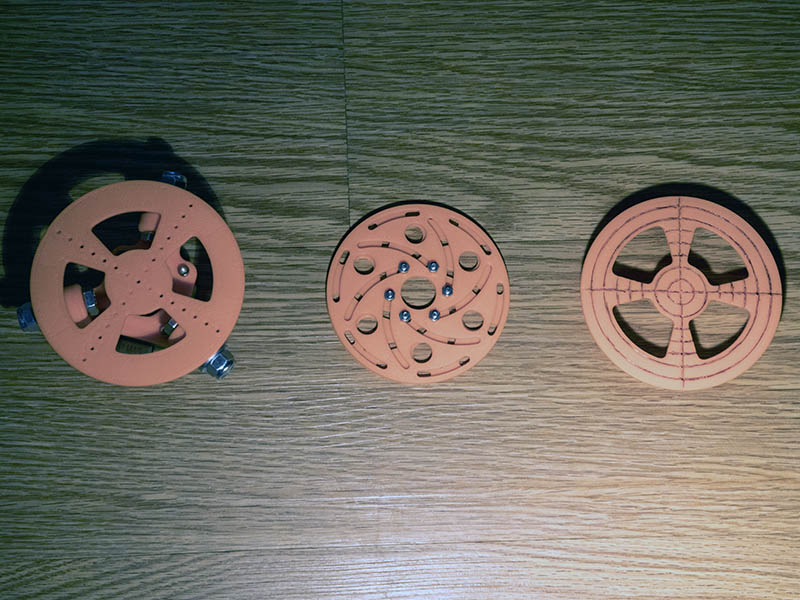
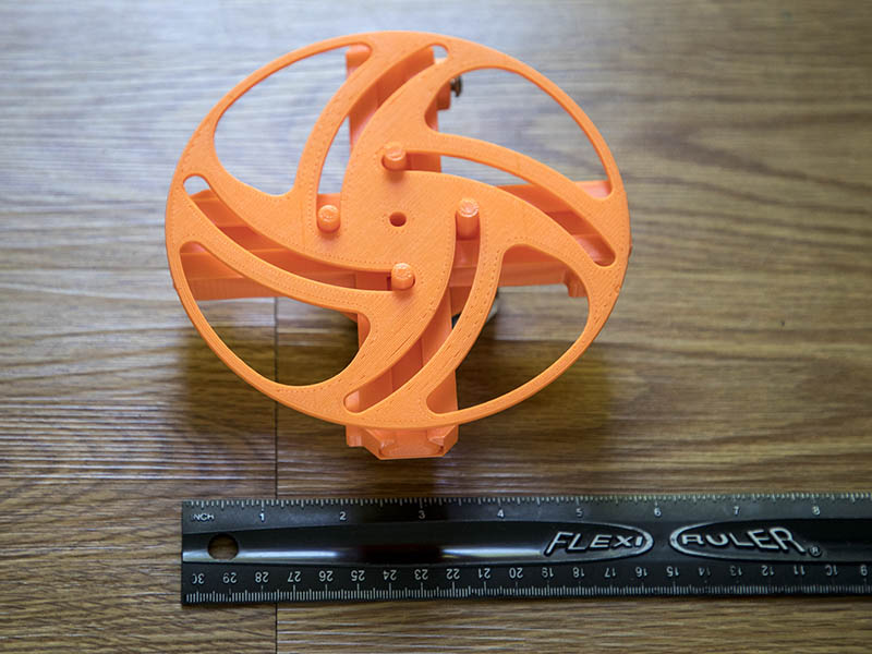
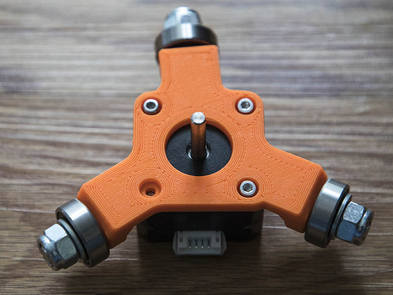
I printed 2 other turntable top ideas. The longworth chuck is pretty cool, but it only gives me 70mm diameter for this size turntable. Actually it could be a little more as I don’t need those outside slotted holes & could extend the other arced holes further. I am going to use it like it for at least the first burn test since for the laser it might not be that critical to get it exactly centered.
I tried it again today & was able to get it to work. I probably had a loose connection with the dupont connectors on the JST plugs on the controller. I am putting JST connectors on those wires today so that is not an issue in the future. I am hoping Lightburn will consider adding the feature of using the X or Y-axis for linear movement in the rotary mode. I am probably only one of few that would like that feature, but looking at output gcode seems like a simple programming addition of swapping G1X to G1Y
Here is an excerpt of the gcode output for rotary mode with Z-axis as rotary axis.
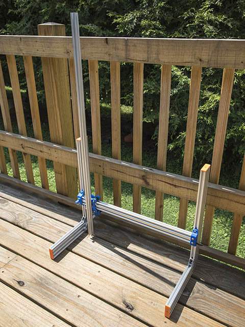
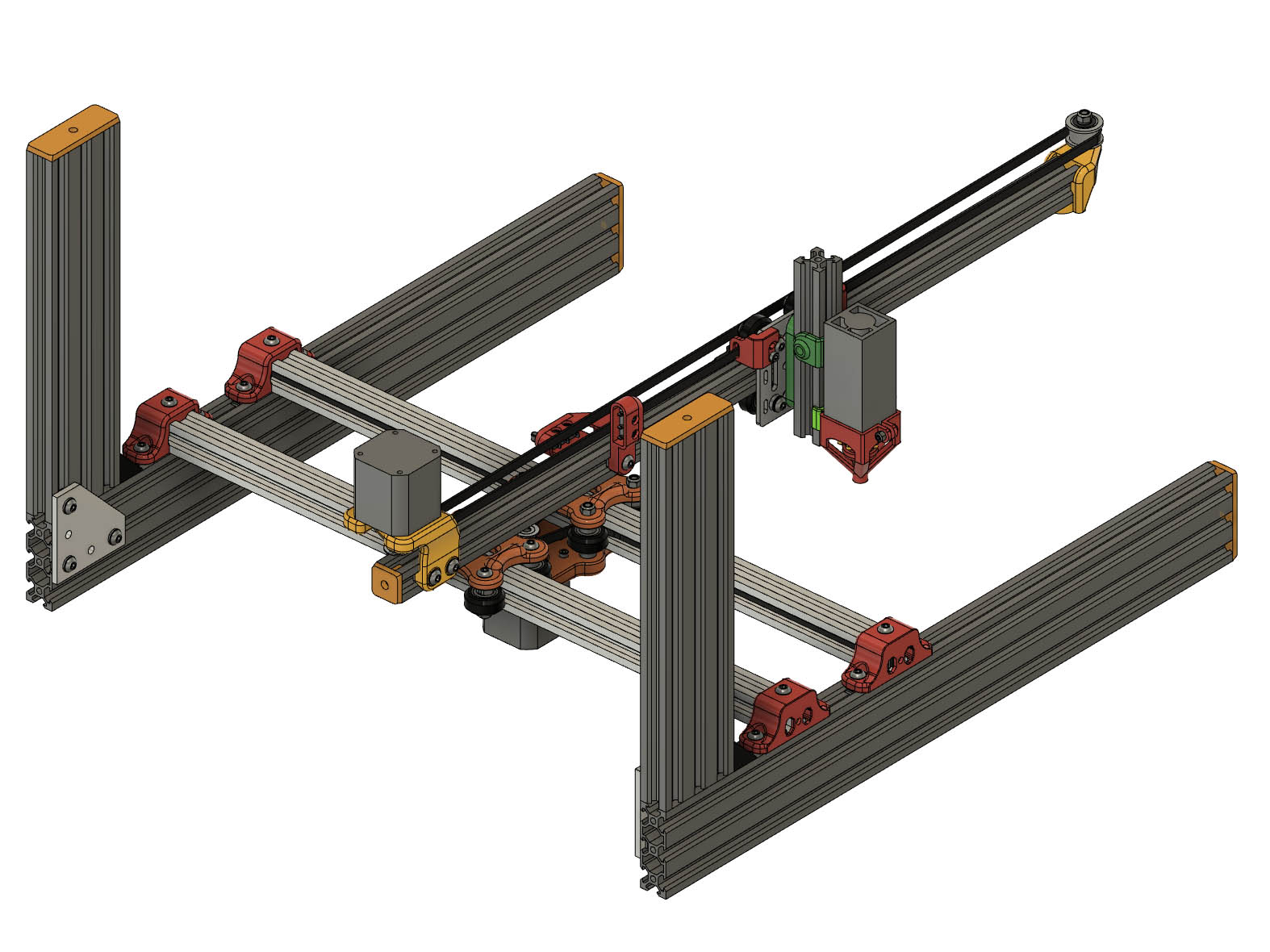
I only had to loosen 3 Tee nut screws to take the 2020 cantilever off & it comes off as a whole assembly which I thought was pretty cool. Could have 2 assemblies, one short & one long. I took this apart to test fit a 1000mm 2020 on there. Seems like in the vertical configuration this extra length will work ok since the cantilever is pointing upward, at least it feels like it should work. I have some extra belt & might test it. I will have to make up a longer cable for the laser 1st. That should give me 705mm (27.75") burning height which is adequate to burn the top railing. Does that sound like it should work? If I cut some aluminum plates to replace the plastic ones, I bet it would be an even stronger connection. Although with those 3 Tee Nuts it is already a pretty good connection.
I also made my JST connections & swapped my X & Y axis as it was the best compromise for me unless Lightburn decides to add the X or Y axis option for the linear rotary axis. I might have to put a hard stop at the other end of the 2040 so electronics or laser do not hit the end.
While playing with the long vertical axis between rain showers yesterday the difference in stability between 600mm & 1000mm 2020 is noticeable on the vertical cantilever, but dry run at the slow speed this runs seems like it will work. I did not get a chance to do a burn test because of the off & on rain.
Anyway, this got me to thinking of using 2 - 2020s in the back instead of the 1 - 2040. Print times will not be that much longer. In the middle of the night I had to get up & put this assembly together to see how it looks. The top plate is duplicated for the back 2020 & the front Tee slot connection is matched with the back M5 hole on the bottom plate. There are 4 extra wheel assemblies & 4 extra Tee Nuts with screws on each end & one extra Tee Nut & screw on back of the 2nd top plate.
I have tweaked this design about as much as I can for now & it works really well in the vertical. 10" paper plate works great for blocking laser light from viewers in that direction.
I found a pretty good design to use as a starting point for a self centering turntable. Guess this is still called a longworth clamp, although the author calls it a slot cam & slider. He also has a Youtube video showing how he drew this in Fusion 360. Slot Can & four Slider Followers
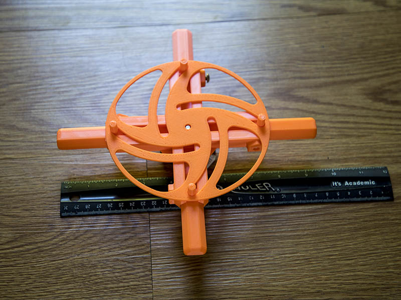
I am using M5 screws with locknuts as simple way to clamp the sliders once it is centered. Thought I would be able to get away with clamping only one of them, but seems like they all will need clamping. That being the case, I adjusted the design to use 3 sliders. I was going to put a 3d printed bearing where the base rolls across, but the 1st print of that failed, so am just making it plastic against plastic. Manually sliding it back & forth feels ok, so it might be ok for now. Probably can use similar bearing idea from previous design for this.
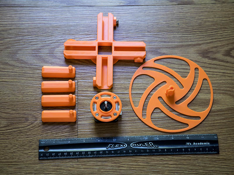
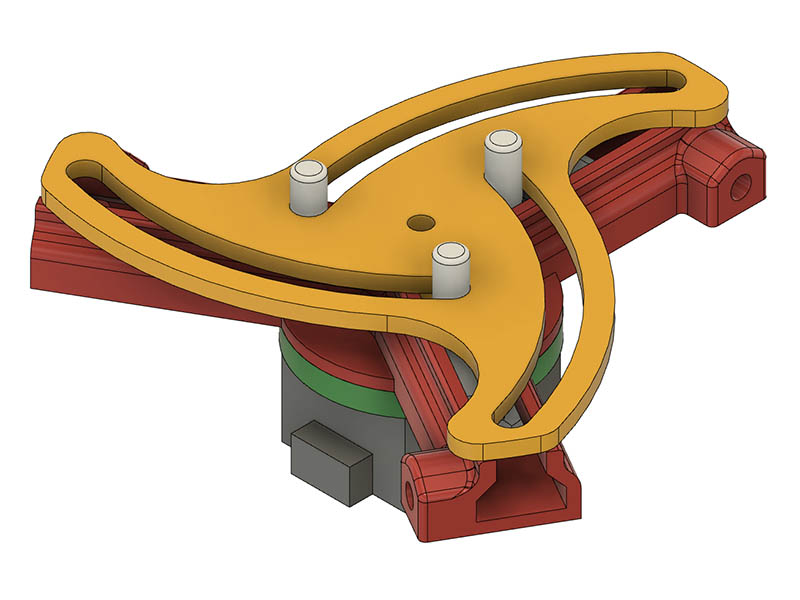
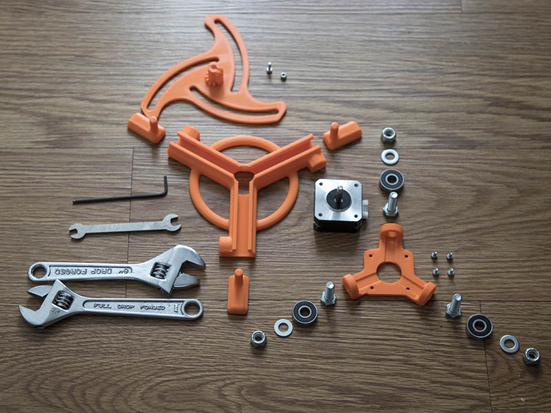
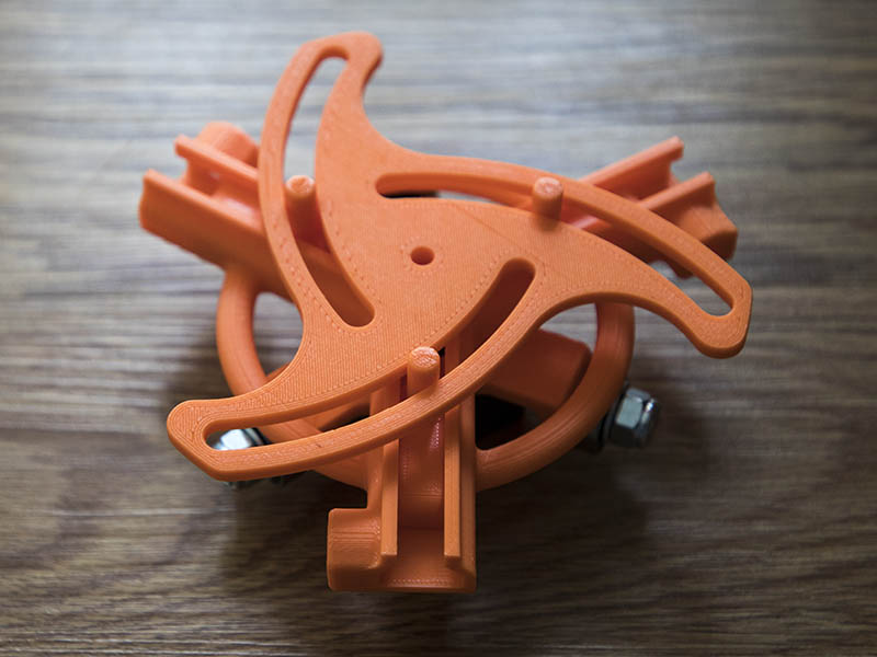
I found a couple of problems with this new version. 1st off, I have no room to tighten the bracket for the top turntable to the motor. After looking at the assembly, I can put the bearing bracket upside down from the way I intended & I can get to that bracket screw if I lengthen the bracket by 10mm. I also printed the sliders shorter this time so they did not stick out so far, but realized they need to be that long when I use the M5 screw & locknuts to press against them. I am not crazy about that solution to holding the sliders in place, but haven’t come up with another solution. For the shaft connection, I maybe able to make it longer & raise the gap between bearing base turntable slider base. Here are photo progress. I forgot to put the 3-M5x12mm screws & locknuts in the parts photo. The 3 sliders do slide better than the 4 sliders.
Regarding the longer peg sliders, what if you just popped the top plate off and spun the peg blocks around 180 and put back in again “backwards” if needing to clamp down on things that are wider? I don’t know if that makes sense or is even possible.
My current thought is there should be a way to use a servo to automatically center these objects, then the servo could hold them in place. Short video below is the idea that sparked that thought. Anyone have another idea along these lines? Maybe I can make it like the longworth clamp (Center of photo shown around message #364) with another top going the opposite way & control that with a servo some how. After some further thought while writing this, think I can have longer pegs, mount the servo to bottom slotted top & rotate a top slotted top. Servo can actually be recessed below the bottom top since there is plenty of room with the long bracket & top top can sit flush on bottom top. That seems like it should work. https://youtu.be/y6wFvbhkiLM?t=126
Peter at openbuilds tells me grbl only supports a servo or laser & can’t use both. That being the case, a 28BYJ-48 or use the pancake motor for that & a larger motor at the base. The motor would be easier to move in steps rather than the servo anyway. I have 3 stepper drivers on that board & only 2 are needed for the rotary axis. I can just swap the cables when using the turntable. I know there is a mod to change the 28BYJ-48 from unipolar to bipolar if I need to.
A motorized aperture like this might also be a good possibility. I saw this before, but discounted it because the apertures come out a ways at full open. If I set the minimum diameter to 1-1.5" it might be reasonable.
I didn’t see what you were saying at first, but that probably would work. It is a little bit of a pain taking those out & putting them back in as the top is clamped to the motor & would have to come off before taking the sliders out. I am using eSun PLA+ which you can bend a little to get them out at the ends, but would eventually hurt the plastic.