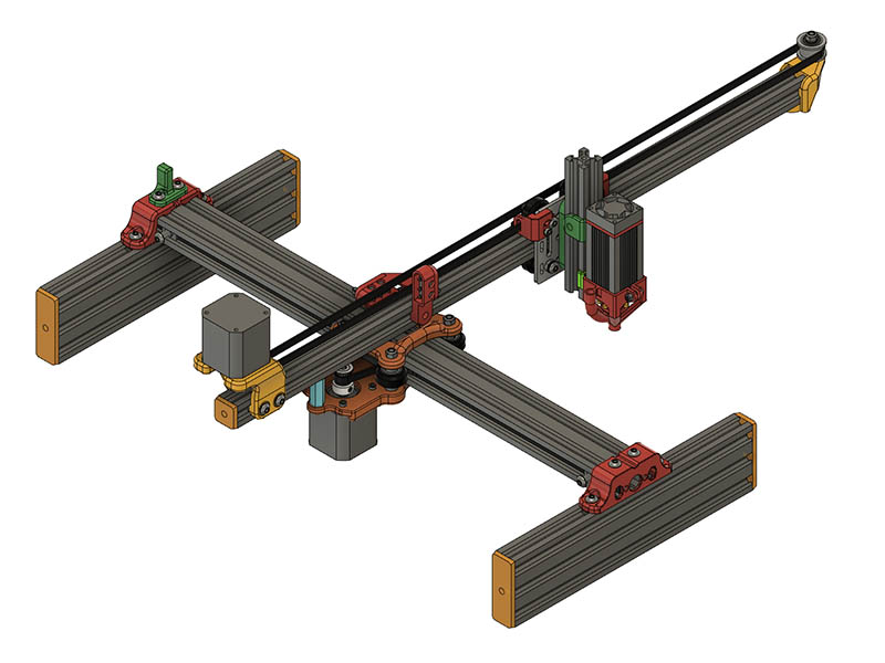
I spent most of today working on making a fusion 360 assembly of all the parts. Here is what it looks like. The 2060 endcaps press fit in so no need for any hardware on those. I might try a press fit design for the 2020.
2 Likes
Can someone tell me what the minimum recommended torque motors for this laser engraver should be? I am working on upgrading my BOM & ones I specified before from Aliexpress ( 42Ncm or 59 ozin) are way too expensive now. Does anyone have a link to a good reasonably priced nema 17 that is not too thick. The ones I am using are about 42mm thick. I have about 52mm clearance for the motor, but do not want to be too close to base. Seems like this machine would not need much torque since it is just moving wheels around. This one from Amazon might be a good one to spec.
Amazon.com: Twotrees Stepper Motor Nema 17 Motor High Torque 1.5A (17HS4401) 42N.cm (60oz.in) 1.8 Degree 38MM 4-Lead with 1m Cable and Connector for 3D Printer : Industrial & Scientific
I used a couple of 34mm deep motors but would think even the 20mm deep nema17’s would be fine because, as you say, there is little load on the motors.
Thanks Mike for your comment on motors, I added that to that build guide. I will also add a link to this build log at the end for reference to any problems they might have.
I decided to create a Mechanical build guide for this new version rather than a video build for now. Here is the 1st draft in case anyone wants to comment on it. I will probably release this design today or tomorrow.
I deleted this guide so there will not be a different version on here & on thingiverse.
1 Like
What an incredible project. Thanks for the amazing work geodave. I’m having so much fun building your machine.
The updated adjustable z carriage looks really stiff and simple.
Looking forward to the updates and will post my build once completed 
1 Like
Looks nice Dave. might I suggest you add that you really need V slot extrusions (as opposed to T slot) for longevity of the wheels, also I think most of these extrusions are available with either 5mm or 6mm slots, and you will need the 6mm slot type for use with 5mm Tee nuts.(ask me how I know that!).
I guess someone really needs to follow your guide while building it to critique it properly though.
Thanks for that remark. I was debating on that because the V-Slot is a registered trademark and some the extrusion I am using from Zyltech is called V-Groove so they do not interfere with their trademark. Guess I should specify that. It is handled in the spreadsheet BOM with the links to OpenBuilds & alternative link to Zyltech. I will go ahead & prefix all the 20xx notations in the build guide with V-Slot.
Thanks for the comments. I could not have started this project without @dart1280 original design as a nice starting point.
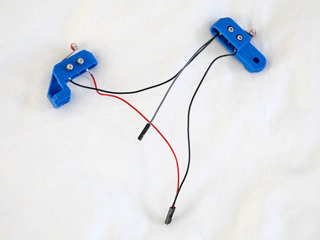
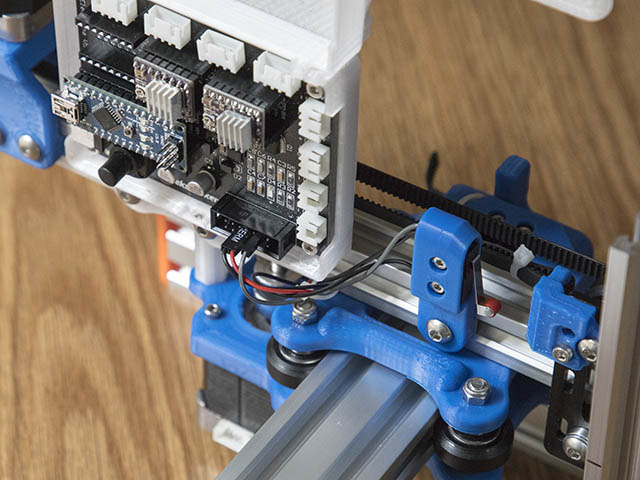
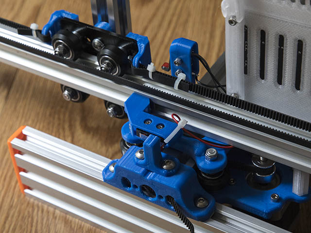
I wired these up as Dan suggested & tested them with the openbuilds control software as Mike suggested & works perfectly. I did have to invert the limit switch pins in GRBL. I was almost too short on the ground wires, but worked out well routing the wires under the 2020 with no interference.
I published the design on thingiverse this morning.
Cantilever Laser Engraver V821 by GeoDave - Thingiverse
7 Likes
Thanks for designing/sharing this! I’ve got an old laser engraver that I think I’m going to tear apart and convert to this as it’s much more portable. Great job putting this all together. It was fun to read through the design process that you went through!
You are welcome. It was a fun design to work with.
Hey dave quick question…is the carriage plate with the 4 wheels attached a printed part or milled/purchased?
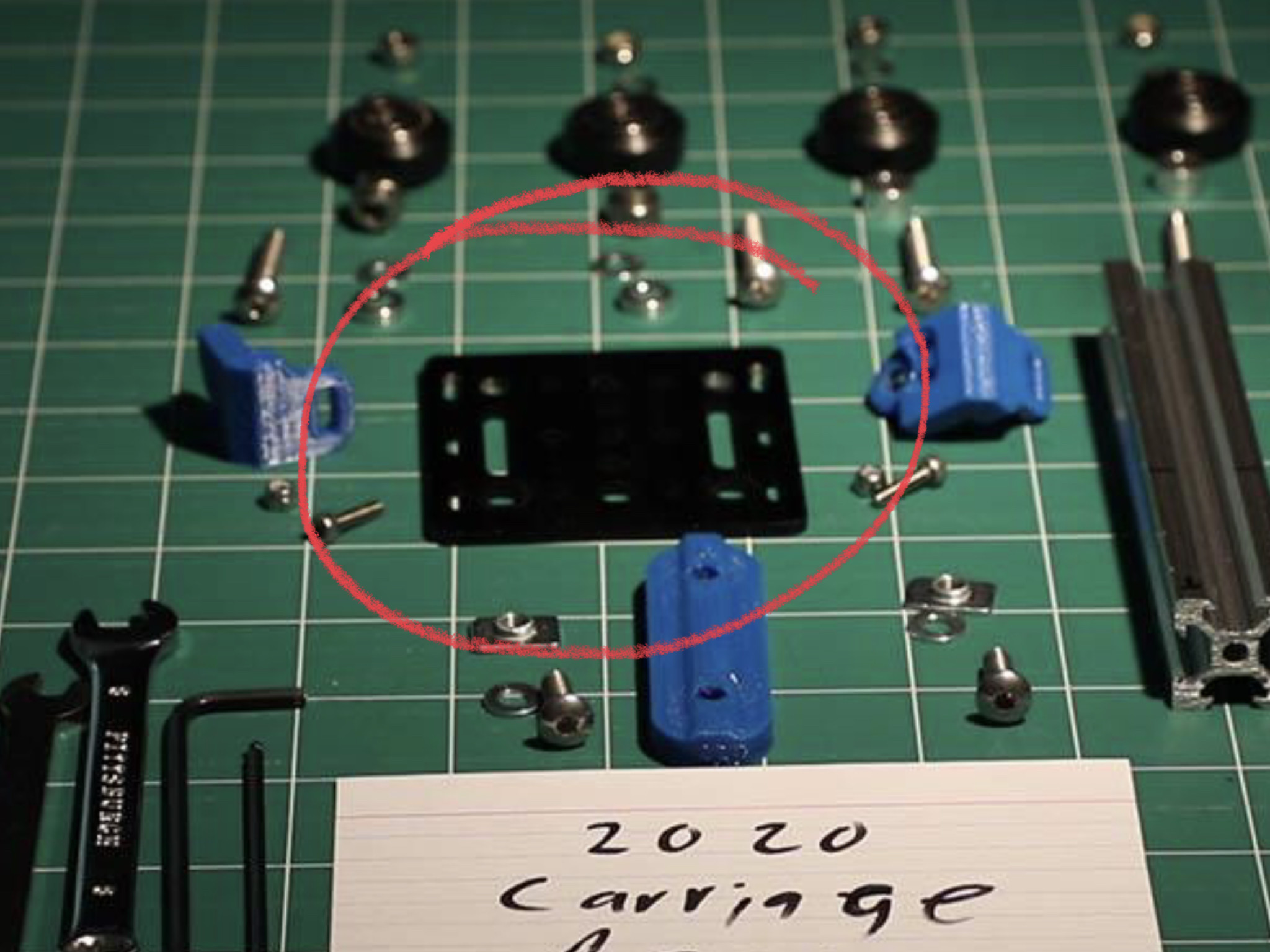
It is a purchased 3mm thick aluminum plate & shown in the BOM spreadsheet. Could make a plastic carriage, but not an expensive part & more rigid than plastic. If you made it out of plastic, I would go at least 6mm thick. Here is the link & alternate source link.
V-Slot® Gantry Plate - 20mm - OpenBuilds Part Store
Gantry Plate Silver for 20 Series V-Groove Extrusion - ZYLtech Engineering, LLC
1 Like
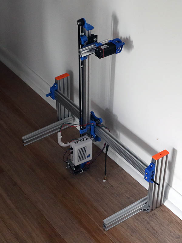
This machine might be more versatile than I thought. Here is an idea I had not considered. Mark at openbuilds asked if it could do vertical lasering with this setup. I moved the feet back enough for the motor to miss the floor & put a 2040 on each foot with one angle bracket & feels like it should work. It might need a stronger connection than that, but having only one screw connection on each member would allow it to adjust a little off vertical if whatever you are burning is not quite vertical. I would also put the 2040 on the outside of the 2060 feet for better clearance of the back motor. A 2020 might also be enough to work, but 2040 felt right to me to test. This could work similar to the LaserPecker, but with more burning room. What do you think?
6 Likes
Now you are fighting gravity one of the larger nema17’s might be needed for the up/down (Y) axis
1 Like
It stays in place by itself except for initially moving a few mms & is not a lot of weight. Think the motor I have is rated at 1.5 A, 0.42 Nm, 59 ozin. Total weight of carriage assembly is probably a little over 3lbs. Once I get it stabilized & enough ballast on the bottom to keep it in place I will test to see that motor is enough. I am going to cut a 1 meter length of 2060 in half today & change the legs from 250mm lengths to 500mm lengths so I keep configuration set for either situation. That makes the machine only 1 lb. 3.5oz heavier. I might just put a piece of 2x6 board on the back as that might be a better weight ballast for it. I could probably go ahead & test the movement before making these changes, but will see if I cant get the 2060 cut first. My problem with cutting the aluminum is covering my miter saw to keep the shavings from going everywhere. I have a little 7 1/4" Kobalt sliding miter saw that works well for cutting these.
I would say the first test looks like hardly anything to change. It does have some settling creep, but that should be easily fixed by making a plastic block to replace limit switch & just slide it to meet carriage & make that Origin for that axis. I am quite surprised at how well this worked on 1st try. Maybe I will try a real test tomorrow on my CNC table leg. Someone commented on the video that reminded to look into the grbl settings again. I am going to set $1=255 to keep motors energized & see if that solves the settling problem.
Here is the video.

3 Likes
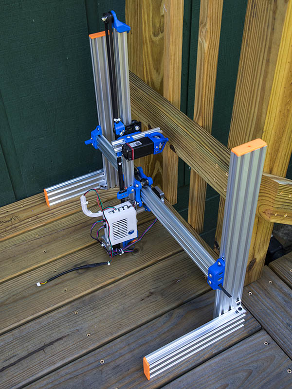
Here is the current setup. Original feet changed from 2060x250mm to 2060x500mm. I used the 2060x250mm for the now vertical feet using 2 angle brackets on each side. Weight is about 8 lbs. 10oz. Since the machine does not move very fast, I did not use any additional ballast.
This is starting to remind me of something you magnetically attach to a vault door. 
4 Likes