Isn’t the pulley at the end of the Y axis adjustable?
Initially I did that, but didn’t work well for me trying to pull that M5 & pulley back so I made it a solid connection. I could probably do with moving the motor back to tighten, but I like the fine tune adjustment of a screw & it is less than 1/10 oz extra weight.
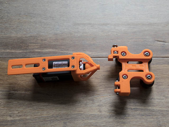
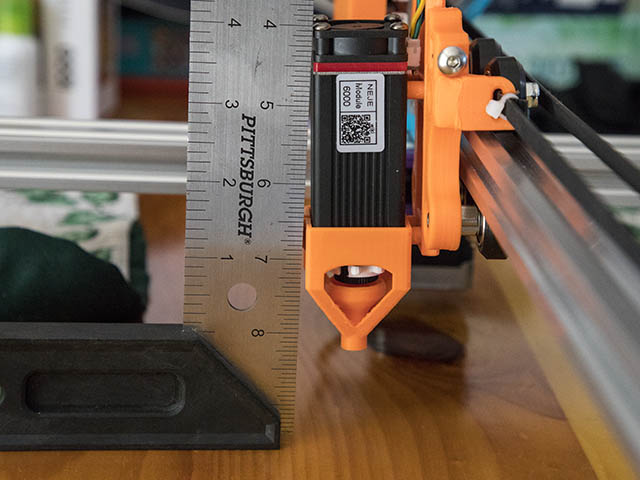
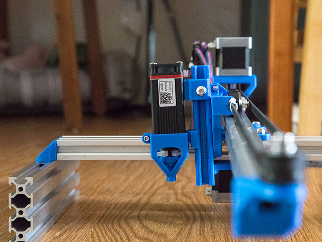
I put the new manual z-axis on today along with a newer version of the controller case. The case needed a little bigger notch for the usb connection. While I had it in the house, I weighed it & it comes in at 5lbs 12oz. I did notice the laser was not quite perpendicular now which for engraving is probably not a big deal. After looking at the photos, that should be easy to compensate for by adding a couple of M3 spacers on the bottom or top connection to get it back to perpendicular. Photo #2 shows the laser connection mounts. Using 6mm aluminum spacers instead of having the 6mm spacers are part of the carriage might have made this connection straighter. I connected laser wiring after the fact & it would have been easier to connect it before mounting it to the slider. Other than those 2 things everything else looks really good. Here are the photos from the install today.

3 Likes
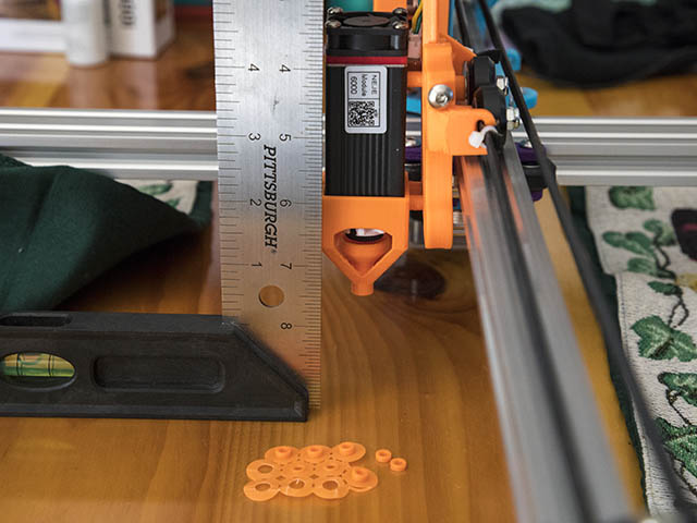
I printed some SPACERS from 1mm to 3mm high in increments of .5mm & settled on 1.5mm high to straighten the Z-axis out. Here is before & after photos.
I started looking at using my Porter Cable pancake air compressor for the air assist. I probably should get that hose & tube kit @dkj4linux mentioned, but thought I would experiment with making some PETG plastic fittings for 1/4" npt. Probably only use one fitting with threads on one end & tapered hole connection for the aquarium air hose.
I find openscad works better for threads than fusion 360 since I can set a tolerance diameter for the threads. I am using the thread library from: OpenSCAD threads
Here is my simple openscad code for the 1/4 Male npt with air hose connection on other end.
include <E:/Program Files/OpenSCAD/libraries/MCAD/threads.scad>
difference()
{
    union()
    {
        translate([0,0,0])
//.25mm tolerance for diameter is = 0.0098425"
        english_thread (diameter=.54-0.0098425, threads_per_inch=18, length=5/8, taper=1/16);
        translate([0,0,-12])
        cylinder(d=18.475209,h=12,$fn=6);		//Add the nut portion
        translate([0,0,-12-3.037])
        cylinder(d1=12.4,d2=18.475209,h=3.037,$fn=6);	//45 degree taper
        translate([0,0,-12-20])
        cylinder(d=12.4,h=20,$fn=52);
        translate([0,0,-12-20])
        cylinder(d1=18,d2=12.4,h=6,$fn=52);	//Add taper to base for better adhering to print bed
    }
    translate([0,0,-12-20-.01])
    cylinder(d=6.4,h=100,$fn=20);		//Cut 6.4mm (1/4" = 6.35mm) diameter all the way thru
    translate([0,0,-12-20-.01])
    cylinder(d1=8.4,d2=6.4,h=16,$fn=20);	//Cut taper hole
}
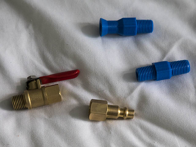
Should not be too much pressure by the time I set the compressor regulator to around 40psi & have a ball valve to adjust it even more. I did a test fit with slightly tightening the plastic fitting without teflon tape & there is only a minor leak. My only concern now is if the plastic part breaks, it might be a problem getting the threads out. Making that connection female plastic threads would probably make that possibility easier to deal with.
Here is a photo of the fittings I printed so far. What do you think of this idea?
2 Likes
Looks really good. I think the safety police would say you need to have eye protection whenever there is a chance it has pressure. But my gut tells me that if it failed, it would most likely crack, and the pressure would escape pretty quickly. It kind of depends on how much air volume is going to move at pressure, before the pressure drops.
It looks really cool.
The other question I have is, are these parts easy/cheap to source in metal? If you need a custom solution, then no. If you are just trying to save a few dollars, then I would only use them temporarily.
1 Like
I am reprinting all the plastic parts for this machine in PETG using 8 Perimeters & 80% infill for most of the parts. Since my shed is not insulated it gets pretty hot in there during some summer afternoons (99 on two afternoons this week). I think the PETG will hold up better in the long run.
I tweaked the design a little since I was reprinting, mostly the main plates & carriage. The 2020 end idler plate I added clearance for the 2020. There apparently was not any clearance before & I probably just filed it to fit.
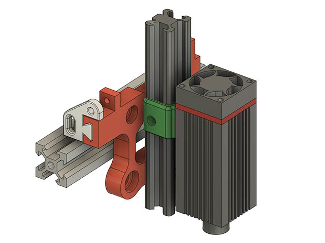
I wasn’t entirely happy with the manual z-axis & came up with a simpler more standard approach using a V2020 for the Z-axis. Actually I am going to try a slightly modified version of the 2020. I cut 3mm off the width. I will make another version of the slider in case someone wants to use the aluminum 2020. Plastic weight should be at least half as much as aluminum.
I have a 600mm length of 2020 & some longer belt, so will test fit to see if I can get a little more burning width. I am using 2-M3x20mm screws with locknuts to hold the the plastic 2017 to the carriage. If I used aluminum, I would use M3 screws with M3 t-nuts. Here is what the new Z-axis design looks like.
1 Like
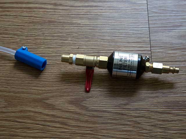
Think I have my air assist connections for the air compressor figured out. I bought a 1/4" M NPT coupling from harborfreight so I could use female threads on the plastic air line fitting. I will put some teflon tape on the last threads when I finalize the connections. I bought a water/oil separator from Amazon as I remembered having some water in the line during my last aluminum CNC cut job so that will be useful for that as well. This filter has a push button drain valve.
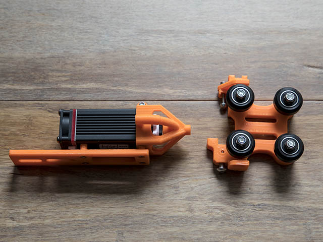
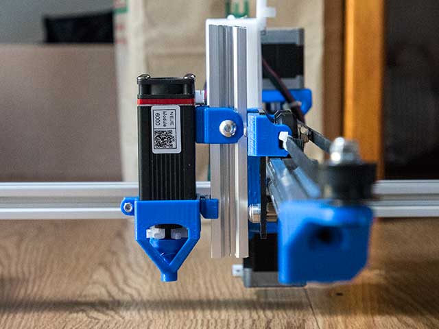
Seems plastic didn’t work well for this plastic V2020 Z axis, so have switched to a metal carriage & real V2020 for Z. It is little more weight, but seems ok so far. You can see a big difference between the plastic & aluminum z-axis in the 2 photos below. I am using PETG with 8 perimeters & 80% infill for all the structural parts.
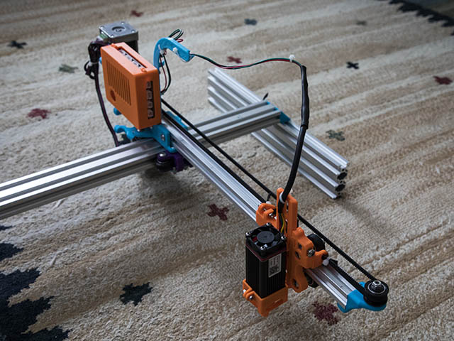
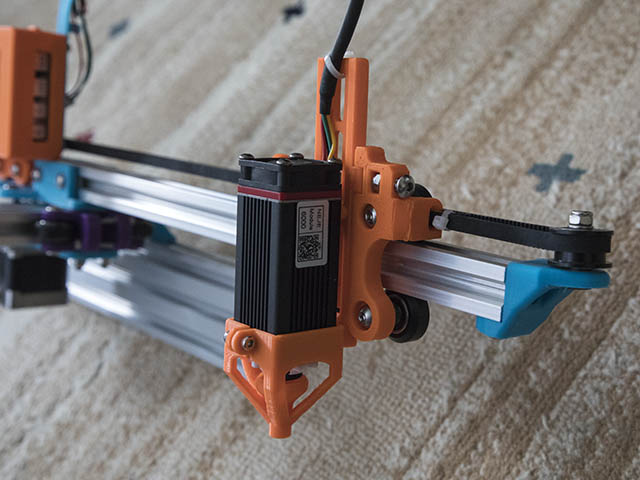
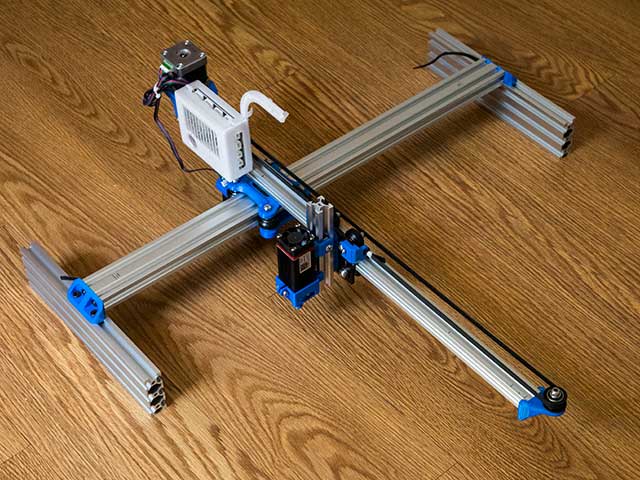
I also noticed about 3mm different height from beginning to end of cantilever, but after loosening adjusting the 2040 horizontal to 2060 vertical extrusion feet & retightening them with the another 2060 & shim under the cantilever it seems level enough. I changed my 500mm 2020 to a 600mm 2020 and now have about 320mm burn width. It was about 230mm with the shorter length. I changed the main 2 plates to use 4 - eccentrics instead Mike’s plastic eccentrics. I also shortened the top plate & took off side connections as neither seemed necessary. Since I attach a long M5 screw between the 2 plates in the back & connect to 2020 with T-Nut, it is pretty solid. I still have a few more tweaks to make before burning again.
3 Likes
I need to make a special cable to wire these limit switches to the Eleksmaker Mana 3 board & I cannot find a definitive answer with google search for whether to use the VCC or SIG connection to the D9 (X) & D10 (Y). It seems like SIG is the one I want to use, but would like to verify this before making a special cable. I really only need to tie the GND connections between the 2 switches, but want to use the 3 pin plugs on each switch to make a better connection. Here is the switch I am using.
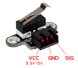
This shows the pin connections with the mechanical switch.
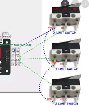
Most setups like to use the C and NC pins on the switches, instead of the C and NO pins like you have indicated. The reason being that if the switch becomes disconnected, or a wire breaks, the switch will then read as “triggered” and homing will stop, instead of crashing the head into the end of the mechanical movement.
My personal preference is to connect the signal (D9, D10, D12) to the C pins on the switch and then GND to the NC (Or, if you insist NO) pins on the switch. This allows the use of +VCC on the other pin if you find that there’s a problem with the pullup resistor. NC and NO will never close together on those switches, so connecting the third pin will never cause a short circuit. If you never connect the third pin, it will never be a problem, so probably doesn’t much matter, just a matter of convention for me.
Yes, you want to use the “SIG” pin for D9, D10, D12. Those switches with the circuit boards usually have their own pullup resistors, so they’re nice to have if your board doesn’t have them, or they’re broken. You can wire all 3 pins to them. Given the diagram you posted, I probably would, in order to be certain that the input is not left floating. So that leaves VCC to connect to +5V (or +3.3V) and GND to connect to ground.
Another question I forgot to ask in previous message was how do you see Endstop states with GRBL? In Marlin you can use M119. I do not see M119 in allowed GRBL codes. I want to be able to just test whether switch is working by engaging the switch before trying to actually home the machine. Grbl v1.1 Commands · gnea/grbl Wiki · GitHub
I tried the $10=16 for verbose status, but must be something else I need to set in lightburn. I also tried the openbuilds control.
Here is another good resource I found for limit switch problems which gave the $10=16.
End Stop / Limit Switch Problems : 3 Steps - Instructables
The openbuilds control does have a tab for checking the condition of all the sensor switches (under 'troubleshooting).
AFAIK there is not a GRBL command to show the switch state, I always check the homing switches (which are also the limit switches) by setting the carriage off in the required direction and then manually operating the switch lever…if the carriage stops the switch is working. 
With the appropriate settings to $10, grbl will include any tripped end stops in the status line, but they only appear in the status when they are triggered.
2 Likes
It seems to have been getting triggered & I did look at the troubleshooting tab in openbuilds control & it showed them enabled. Some how the firmware got messed up as I could not move either x or y axis. After reloading the firmware the motors worked, but took the endstops off for now. I might try the simpler mechanical endstops to take the extra complication out of the equation. I currently took the whole machine apart & doing assembly videos with the new version of the parts. I will try the endstops again after I finish these.
I’ve tried a couple of different times and a couple of different ways to use those endstop boards with LED’s in a Normally Closed configuration and never been able to sort them out. I just clip the switches off the circuit boards and wire directly to the switch pins instead. I don’t need the additional LED feedback on the CNC, although I do like seeing it on my 3D printer.
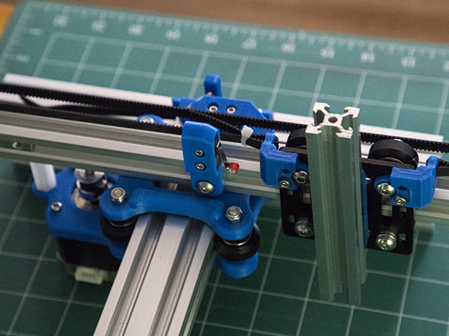
While taking this machine completely apart & putting it back together with some instructional videos I started rethinking these end corner brackets. Since the plastic parts have a little give to them, I have to loosen them in the tapped 2040 holes, adjust the cantilever beam to be parallel with base & tighten those screws again. I came up with 2 different versions of a wrap around bracket. I chose not to use metal angle brackets as I would loose even more burning width since I would then have to move the t-nut belt clamps, but that is still an option. I have printed the version on the left & test fitted them & it feels pretty good. That version I printed on its side & the 2nd version I am printing upside down with supports for the outside holes. I made them 18mm wide instead of the 20mm width of v-slot to cut out a little plastic as it didn’t seem necessary. Any thoughts on these ideas?
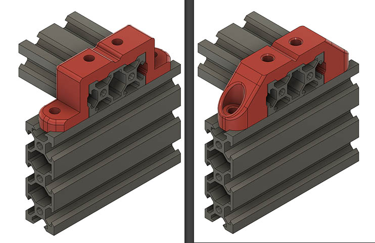
I am leaning towards the 2nd version as the print orientation seems better & looks cooler. Will see how the difference feels when I put that on. The advantages of this design is no tapped holes are needed, a stronger connection & might not need to adjust the level of the cantilever 2020 since the 2040 is sitting directly on the 2060s. The only disadvantage I see is loosing 25-30mm of burning width. I had 410mm before, so 380 is sufficient for me. I could always go to a 600mm or longer width if I needed.
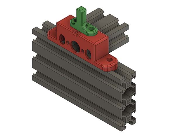
I also designed some mounts for mechanical limit switches. This is a similar design I did a few years back on my 3d printer to cover the electrical connections better & has been working well. With the new 2040x2060 brackets I will have to make a different end stop for the X-axis so I do not loose any more width.
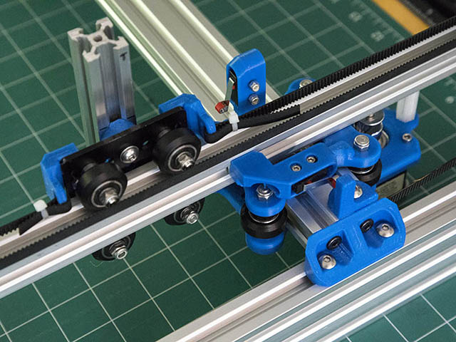
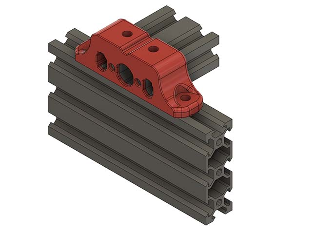
They both feel about the same to me, so am going with the easier option & adding a 2mm backing to it to cover share extrusion. The green part is the X-axis stop block for the limit switch.
I kind of liked the second one better. I agree it looks a bit better but I also think the additional support in the angles could keep it more rigid. You could add a little plastic where the countersunk whole starts and then drill it out later. This way you wouldn’t need any supports. I don’t know if I’m describing that well so let me know if it didn’t make sense.
BTW, I really like this project. It makes me want to disassembly my old laser engraver and make this one instead!
Thanks for the comments. I am kind of going back & forth on this. I might print another one with 2nd version with the added cover & see how that looks. Think I can print that on the side.
I decided on a compromise between the 2 designs. I might be finished with this version redesign & should be able to release the STL files in next few days. I am calling this version V821 for August 2021.
1 Like