Totally new to CNC. I bought the Jackpot 3 motors and everything Ryan had in stock from V1 a couple weeks ago. I ran the test that tells the firmware and when I was searching other peoples posts about x or y axis problems. I believe mine to be the lates I think it was 4.1.1 but not 100% the correct number. I need to enable 2.4 on my router so I can hook my jackpot to my wifi. I have tested both Y axis with $LIMITS what I assume is y min the rear of the machine Y max the front of the machine. I have both Y min wired together and Y max wired together. When I click the y min switches I get a small y in the terminal. When I click on the front switches I get Y. I tell it to go to Y - it goes to the back of the machine. I tell it to go to Y+ it goes to the front. When I click Y home it goes to the back when it engages the switches the left motor shuts off now but the right motor keeps grinding. This is after many hours of fighting and forgetting that these switches are closed when not engaged and open when engaged. Since the switch works with $LIMITS I don’t understand why it is not working correctly when homing to stop the right motor.
Hi, I’am guessing that since you can see “y” and “Y” when you enable the switches with $LIMITS , the Y min and the Y max are switched?
So Y is min and y is max? I’m going to switch my cables y0 and y1 cables to test if the issue moves to the other side.
To be honest, I’m not sure, but I think that the side with the rail is Y.
I swapped y0 and y1 and the problem switched sides even though the switches are wired together. The issue is on the A motor controller which ever motor is plugged into it does not shutdown when the limit switch is engaged.
How do you mean?
As far as I know on the lowrider Y axis is the forward and backward rails and x is the gantry left and right, and z is your up and down. Y0 is toward the rail and Y1 is the other side y max. I need to go over the documentation more since I am new to CNC.
The front switches are wire in series (I think that would be the correct term) and the rear are wires in series since you only have 2 y connectors on the board. This how I assumed they should be wired bc I could not find how they are supposed to be wire in the build instructions or on any video’s I watched.
Ok, another guess, you have wired both sides of Y min to y0 and both sides of Y max to y1 or vice versa?
Both y0 and y1 are on the y min side? Could you post a picture of your machine?
Pictures would not show anything at this point it is a birds nest. I cut the y max (y1) switch and y0 attached to motor controller “A” still grinds and y1 (y max) motor shuts off. Sorry if I have the naming wrong but it appears the issue is with motor controller “A” since the “Y” motor controller shuts off. I don’t know if this is a YAML issue and I have no clue about YAML I have just read it in many of the threads that I have been researching. I am running a bone stock Jackpot 3 that I received in the box from V1 engineering.
Maybe read this post?
Thank you very much I will check that one out. I’ll try switching to homing to the front but that is where all my troubles started lol so I tried homing to the back but probably made things worse.
I switched it around to home in the front like I was supposed to and problem followed the “A” motor controller does not shut off while the “Y” motor shuts off correctly. I guess I will post on his post to see if anyone knows why the this is happing or if there is a software fix for it.
Are you building a LowRider or ZenXY? This is posted in the ZenXY section but it sounds like a LowRider.
My bad I am building a Lowrider I don’t know if the mods can move it to the correct area or if I need to create a new thread there. At least with waimea help I am farther along.
That helps!
I will admit that I am also confused about the limit switch wiring you’ve described. The LowRider v4 build has 5 limit switches: Z, X0, X1, Y0, Y1, and each has a spot in the Jackpot 3 to plug in so I’m not sure why you would need to wire any of them “together”. A few pictures, even of a rats nest :), where you point out which switches you are wiring together might help identify the issue.
I think there is a typo in there, there is z0, z1, x0, y0 and y1?
So how do you wire in the Y max switches since their is no port on the board. I wired them together Y0 min and max and y1 min and max so when both switches on Y0 are engaged both motors should shut off. When the gantry reaches y1 on min and max the circuit is now open and should shut the motor down. So I should just use Y0 min and Y1 max and not connect the switches to anything? I tried that on the max side by cutting the wire and it Motor A always stayed engaged.
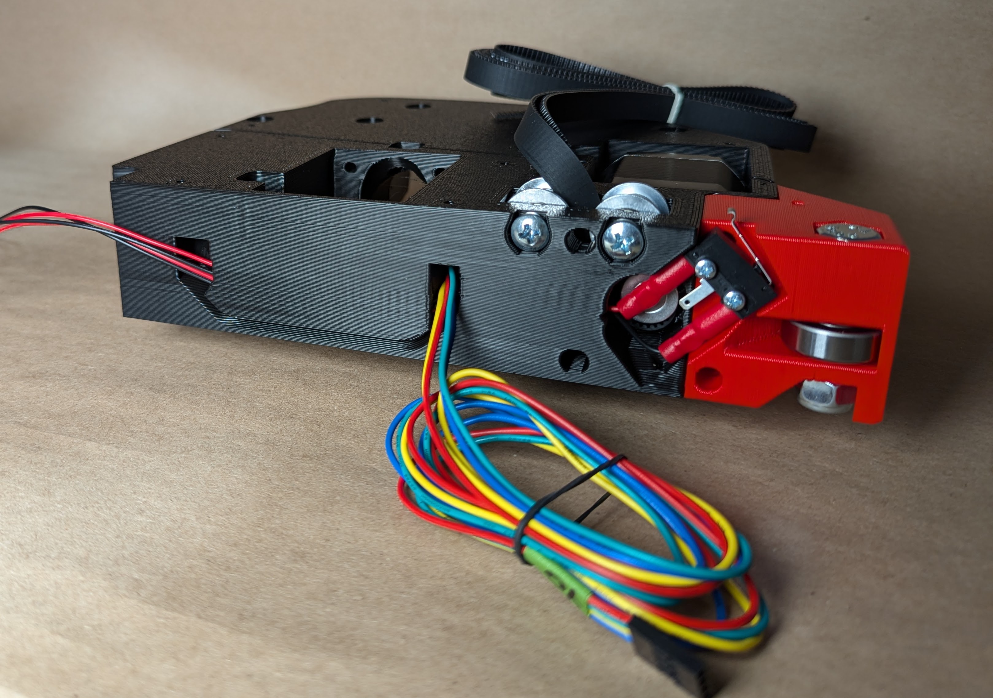
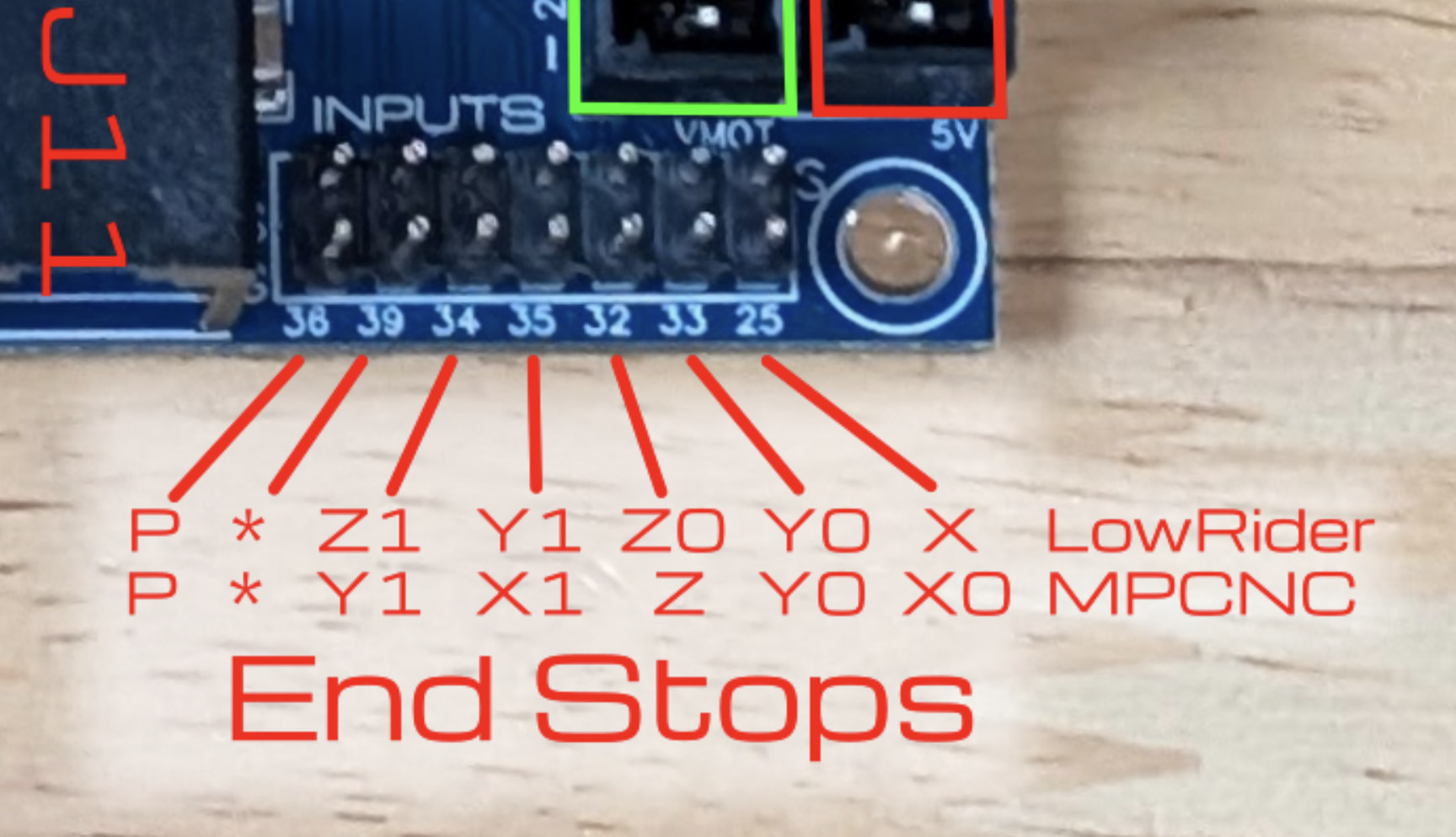
Oops! Yup, typing quickly before running an errand and didn’t proof!