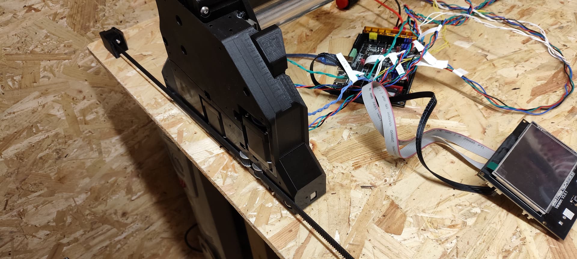
My LR4 build is pretty much done and I have tried to follow the instructions as closely as I can, but some bits are really vague.
My build has a Y axis endstop facing forward and one facing backwards, and it seems both of these have to trigger for it to home properly. But if it homes in one direction only, this obviously wont work.
Can someone explain how I can get this working properly? Is it mechanical assembly or firmware issues?
Basic usage it is only recomended the FRONT OF THE MACHINE to be the homing side. You can home to the back side but it is considered to be an advanced option
So does this mean I’ve assembled everything correctly? And there’s a redundant switch at the back? Is it supposed to be left unplugged?
I’m running Marlin (SKR PRO V1CNC_SkrPro_DualLR_2209-2.1.1) on an SKR Pro, this seems to use both Y endstops out of the box.
How would you recommend setting this up?
P.S. I’m not a n00b to this kind of motion system and configuring marlin, so I’m not intimidated by advanced options. I’m just curious about understanding the theory and intent behind it so I can use it effectively.
You need at least Y-endstop switches on the front of both Y cars. I don’t know about Marlin/SKR Pro, but the normal homing mechanism is that the machine will drive forwards until both switches are triggered, then pull back some amount to pull the gantry square with the rail (this is discussed in the ‘squaring’ section of the docs.)
Your assembly looks right to me. There are (normally unused) slots for rear switches on both cars. As long as you have the ‘front’ switches (actually sticking out the side) on both cars, you’re good.
If your machine moved backwards on homing, flip your stepper connectors into the board.
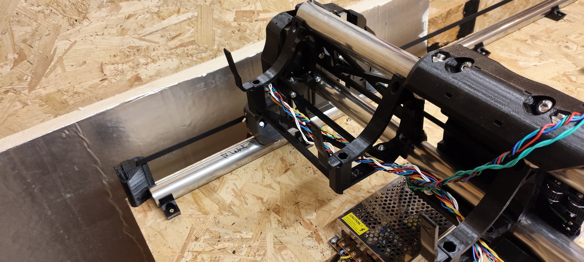
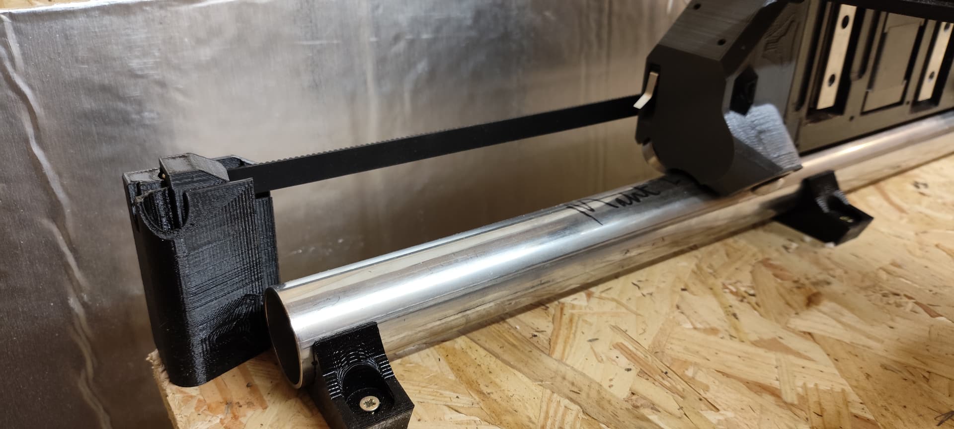
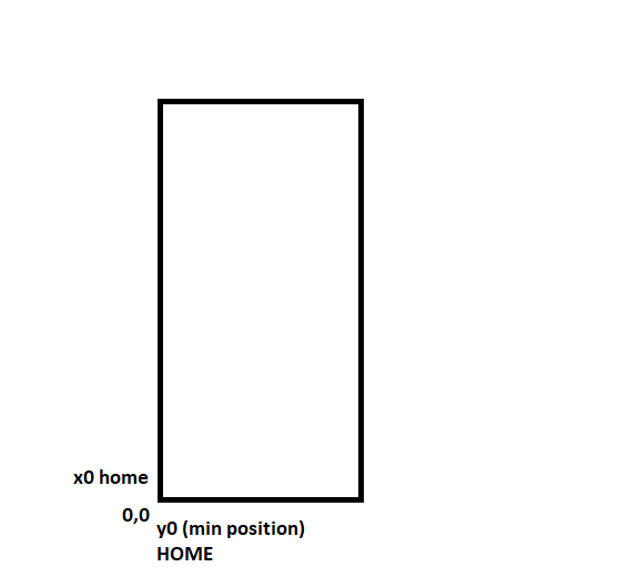
What’s throwing me here is only one of the switches is sticking out of the side.
There’s another one on the opposite side that’s pointing towards the rear, in the opposite direction.
So it would seem this switch needs to be moved to the underside switch slot on frontwheel_min (i think. …this would be much easier to refer to with a CAD assembly!)
the hole it is there for those who are going to be homing to the back ( if you are going to home to the back you arent populating the front ones) just leave them and dont connect them
what happens when you move your machine y +10 ( moves back or to the front according to the image?) - if it moves back just turn off the power and flip the conector to The driver
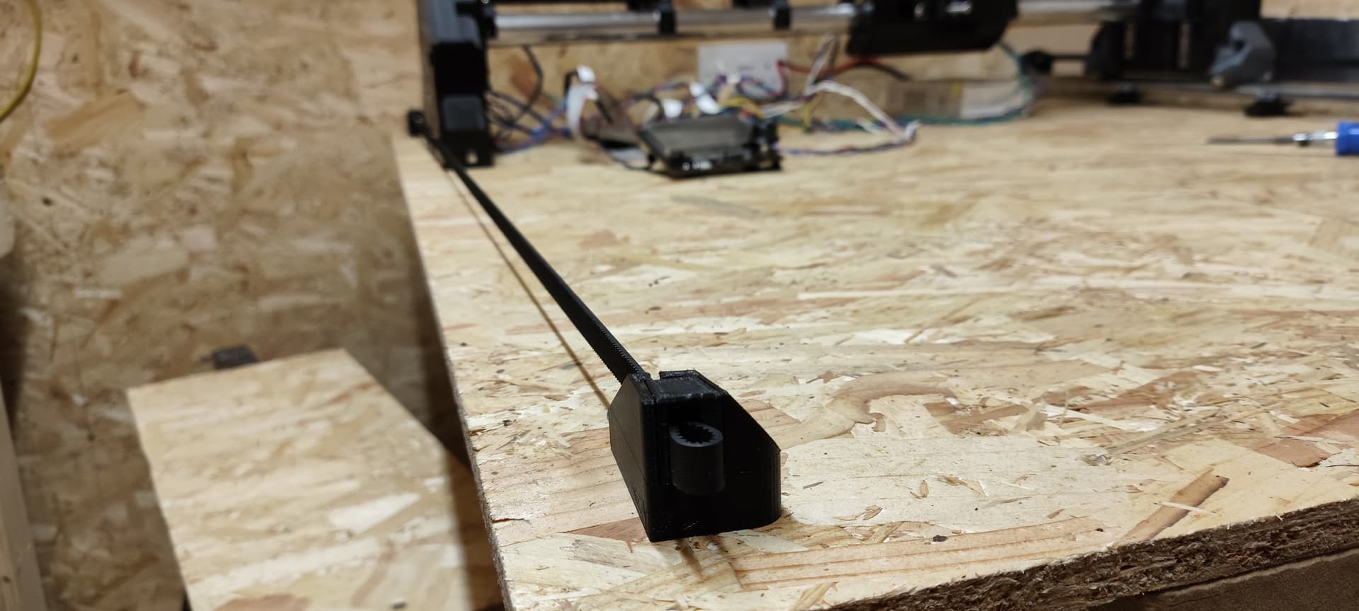
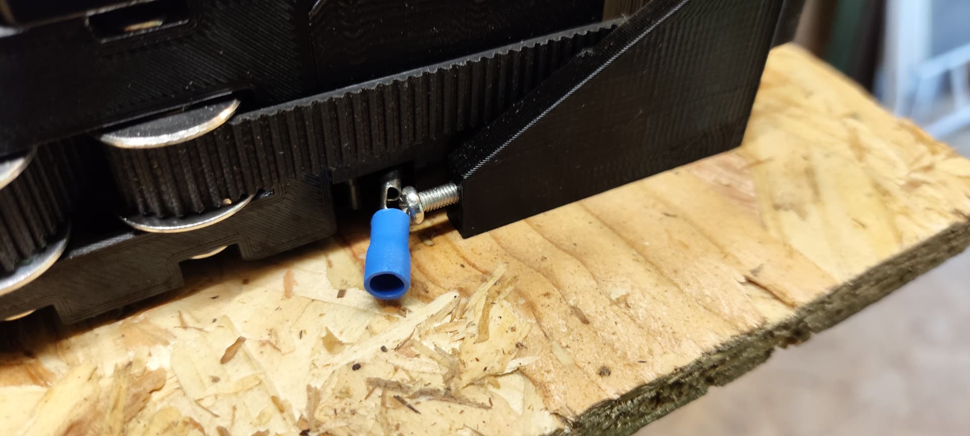
Ok I got it working! I moved the switch as discussed, and it crashed a couple of times, so I put some spade connectors over the microswitch levers on each side and it’s homing pretty reliably now.
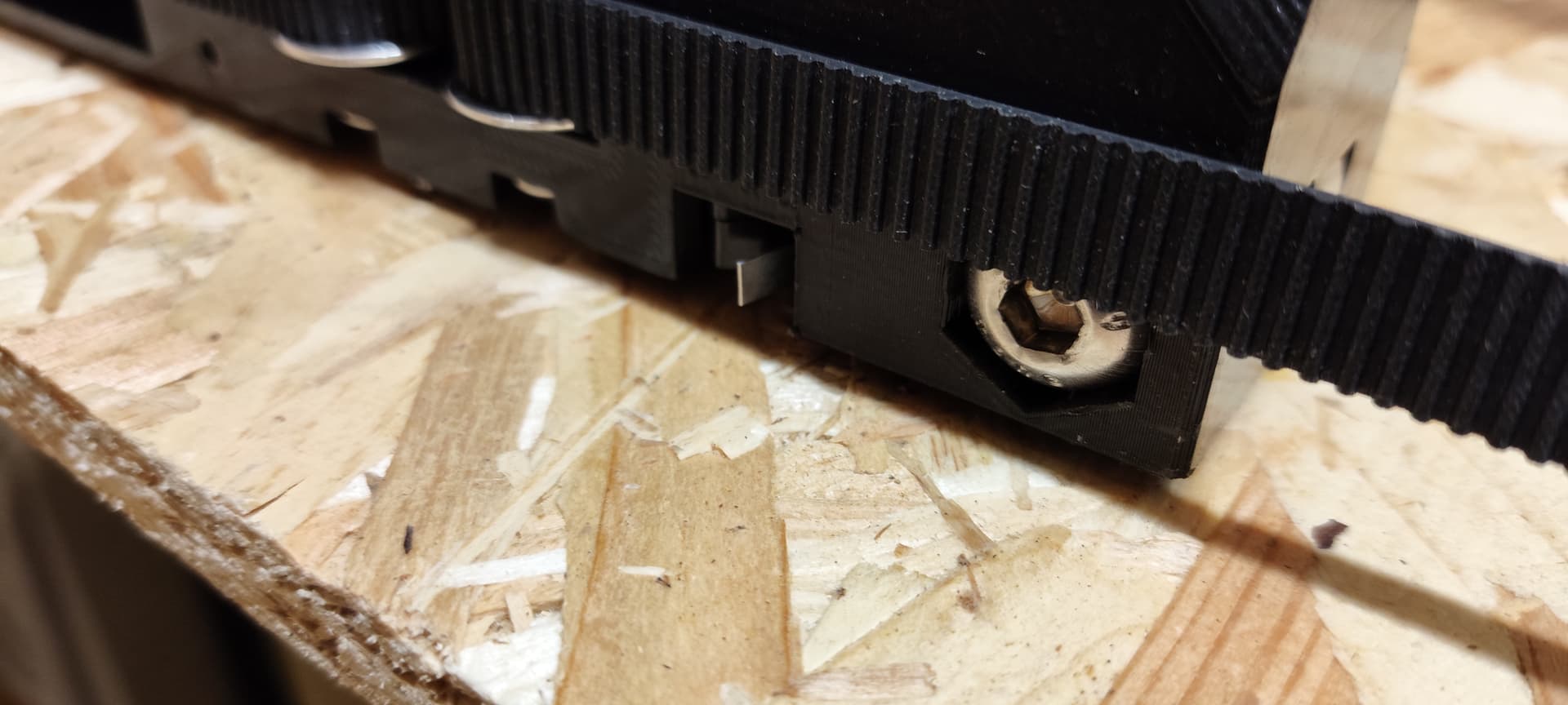
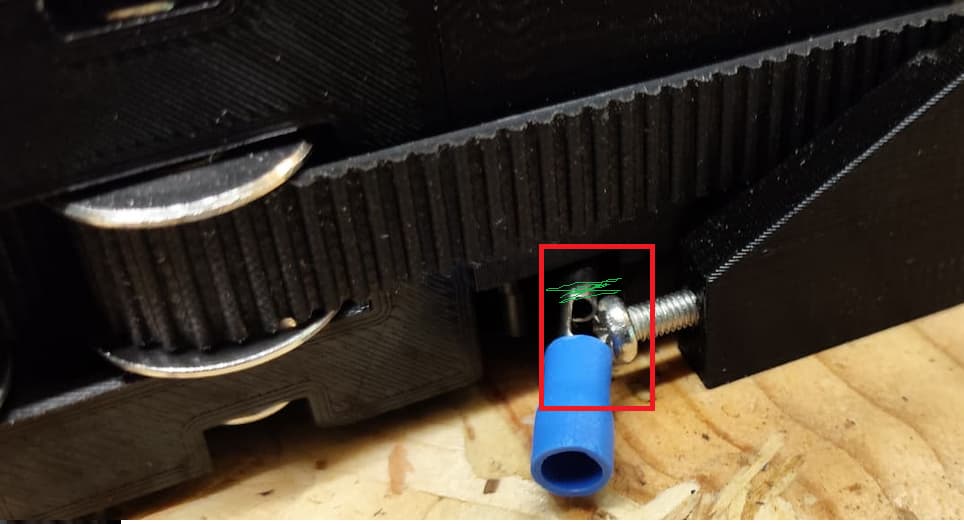
The pic isnt so clear but they stick out enough to make contact when the spade connectors arent attached. The problem is they then clip past the bolt im using. The switches I used were the ones specified in the BOM, but I guess the lever isnt long enough.
Anyway, my spade connector hack seems to work well enough so it will probably become permanent.
If you use a socket head screw on the y endstop you may have better luck with the switch tab not going past. Have you tried the switches with the roller on the end?