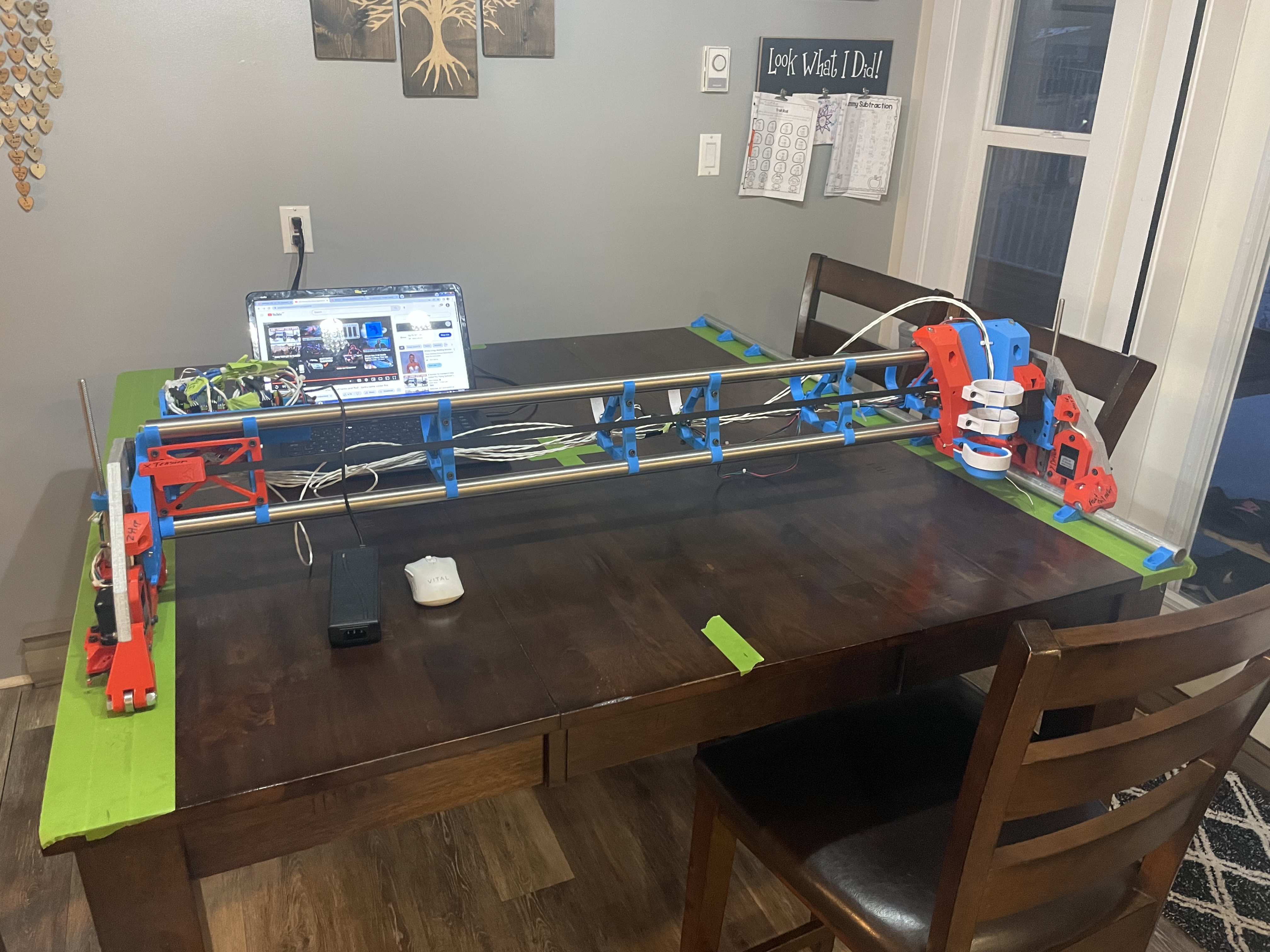
Haha yes I do I was just kinda laying things up and sitting back and trying to figure how I am going to do this lol.
54” width and I need minmum 60” I believe to cut gantry strut for my 4”
I might get 2 sheets of mdf so I can make a extension on the table to do the cut.
The plan is to cut a recess in the table for my tempered glass for Zenxy.
2 Likes
Ok I think I have decided to make two y rails.
One for my table cutout. And one for at work for full 4’x8’
We have nice tables there but they are 4’x8’
So I am thin king of getting 2 sheets of either MDF or plywood hood one side or I will epoxy flood the ends that have the rollers.
I was going to put them as if to make a 8’x8’ or now that I am thinking about it probably best to trim each sheet so I don’t have a huge overhang.
Like maybe go two 5’ sheets so it makes a 5’x 8’ table. Does that make sense ?
I could put a couple boards underneath to tie it all together so I can remove and put aside for longer cuts as well.
2 Likes
Sharp looking build! I was going to call your color scheme “Captain America” but since it’s Canadian, I’m going with Captain Canada! You can tell people that “CNC” stands for “Captain 'N Canada”! ![]()
1 Like
Haha I am literally on the border
Thanks I appreciate it
soon I will make some things just half asking and also documenting my odd process.
1 Like
Uh oh. If you are married, i think you will be in TROUBLE, LOL
2 Likes
Heh, we had that table in our last house. ![]()
3 Likes
So I went about things oddly and here I am.
I chose a square table and I would not recommend one that is under 60”x60”.
Since this is a temporary build I made two piece 1-4” plywood struts. I will add a little doubler over them I think.
Aside from all my mess ups the machine works great what a sweet design.
On a side note I had issues trying to use estlcam, and I originally couldn’t get the customizable struts that someone spent a lot of time on to work.
Was going at it as a “part” and should have went with a engrave move. As it would not let me do a part that wasn’t fully closed off. Anyways I have learned a lot already.

If I was to do it again I would have made a proper table done my custom size struts and the full size ones and then re mounted on temporary table.
3 Likes
It’s easier to do the milling on a too small table if you add two pegs you can then use to just flip the board over, perfectly aligned.
2 Likes
Damn that’s a amazing idea.
So have two common dowel pin spots that you align with your cam software. Then you can flip and keep things aligned.
I was a bit off so I had to cut them in half.
Yes, like this (blue are the dowel holes):
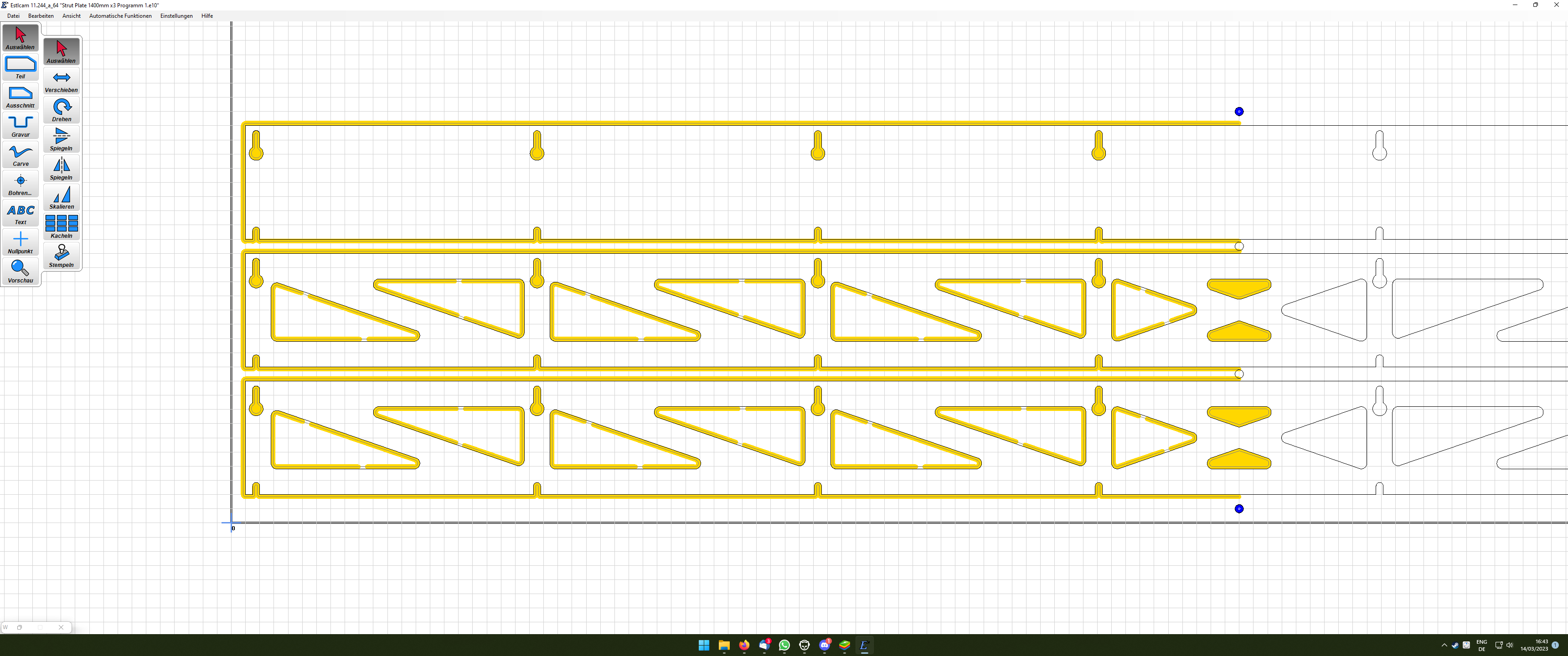
Obviously the second program does not have the middle parts and dowel holes cut out, but the rest is identical. ![]() Just remember to take the dowels out (or make them low) so the CNC does not hit them, nearly happened to me.
Just remember to take the dowels out (or make them low) so the CNC does not hit them, nearly happened to me. ![]()
2 Likes
Big oooof here lol thanks so much for the visual I spent a good amount of wasted time building my ugly heavy ones.
So you can open the variable file then simply use the not automatic function and engrave to only do partial cuts ?
Literally spent hours trying to do it lmao
1 Like
Yes, I chose “engrave” for the halves, then clicked “manual”. If you then move the mouse close to the end, it is going to highlight a path for you. You have to then right (!) click and it will create a toolpath along this line (you can switch outside/inside if it does not match). If you left click, it will create a toolpath from where it was to where the mouse is now, so don’t do that. The file are the whole strut plates, but since they would have gone over the borders, I just didn’t create toolpaths there.
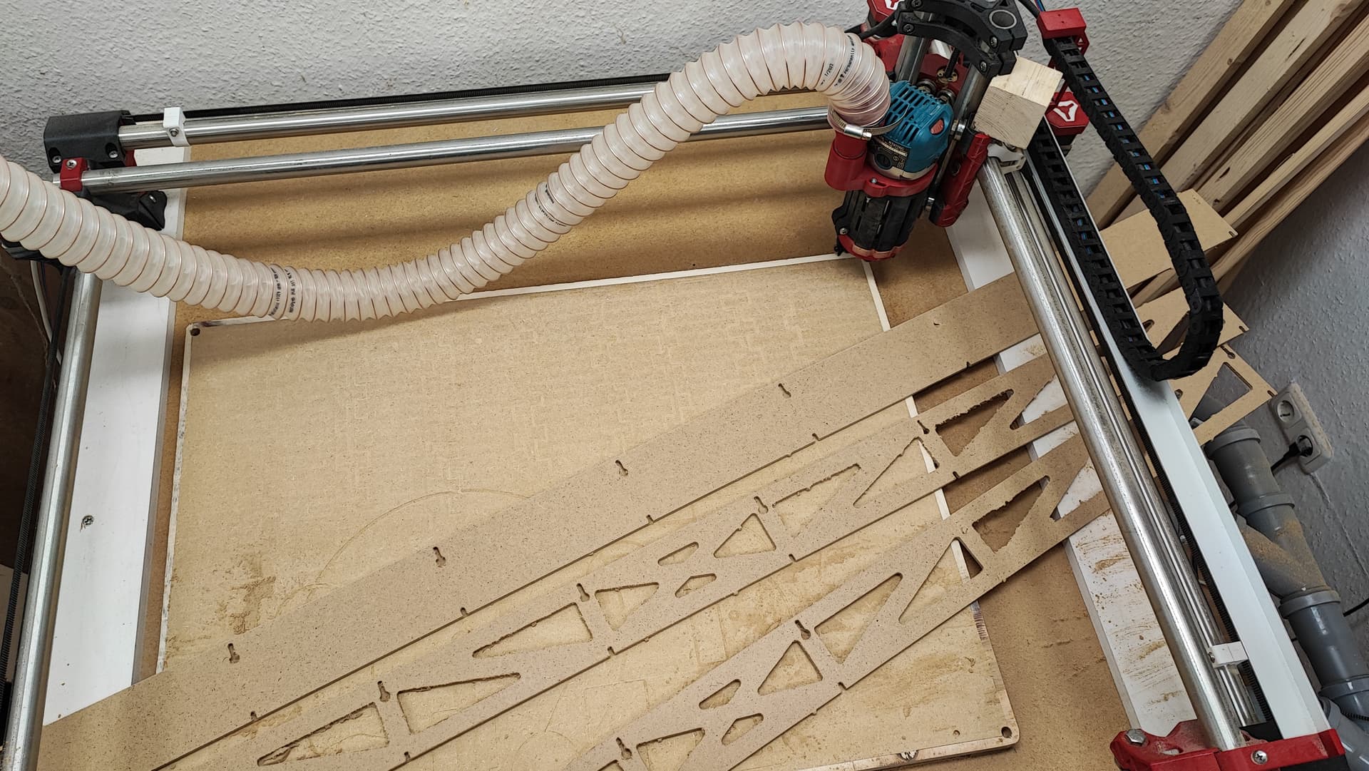
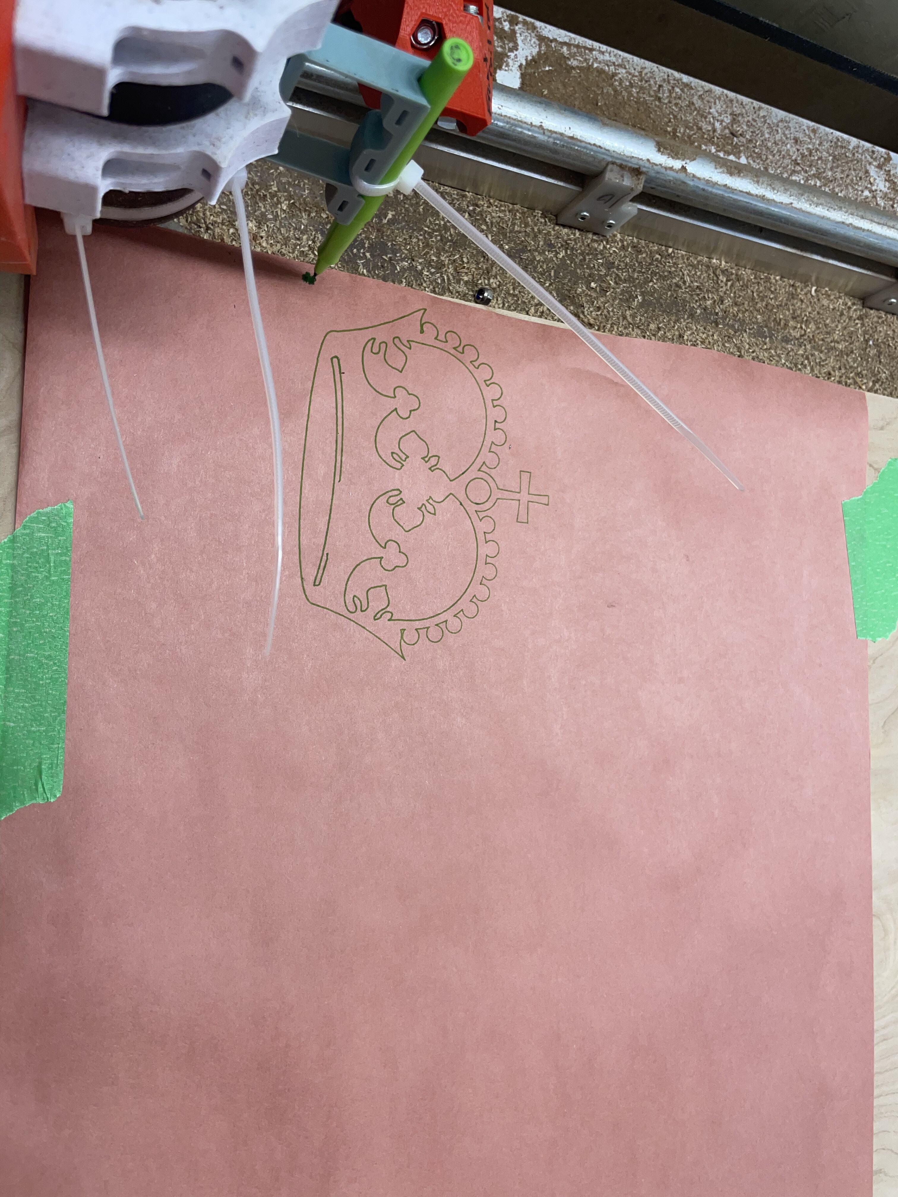
The peg can be seen just below the gantry, top right of the cut:
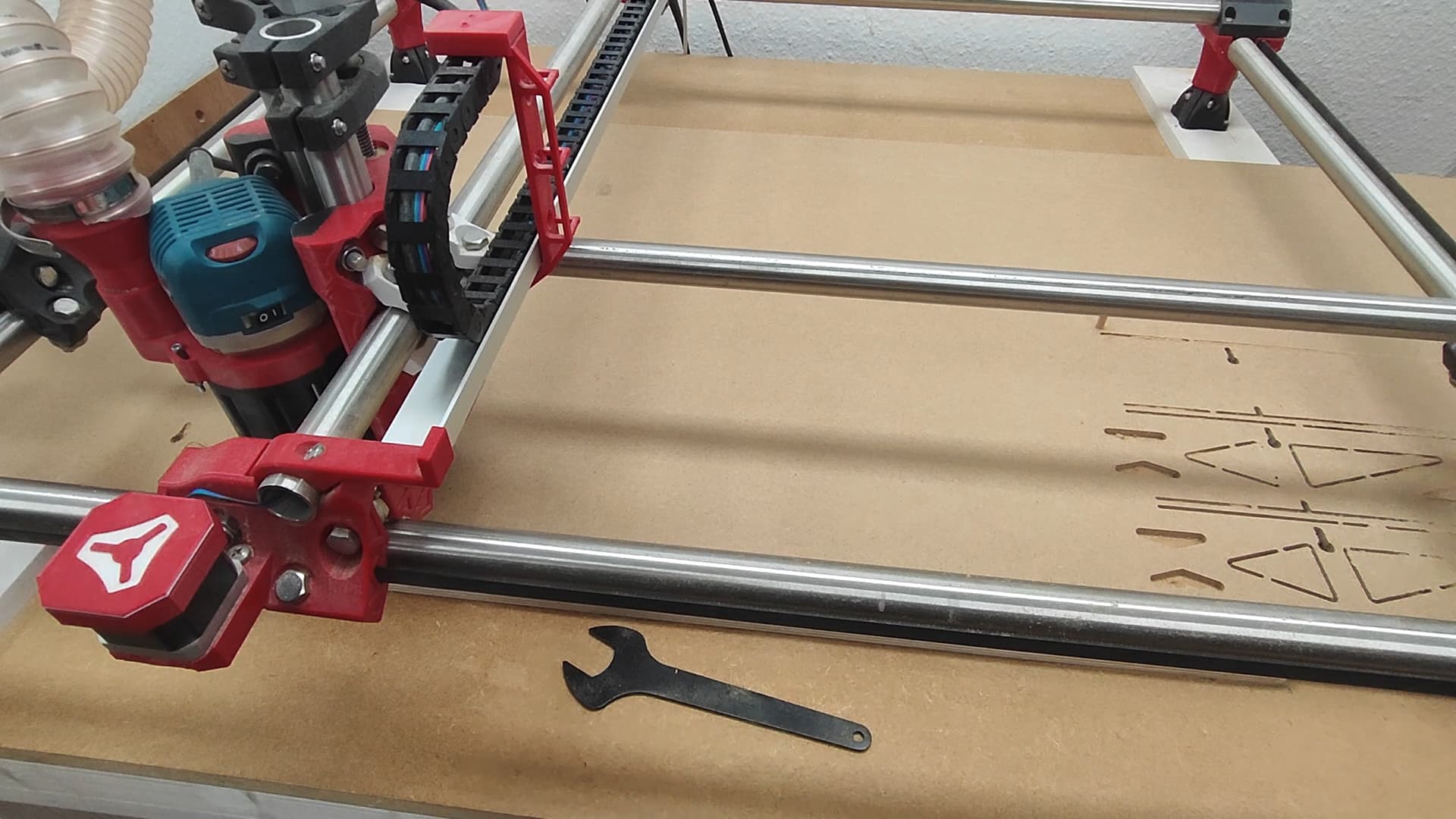
You can see one of the holes for the pegs in this one at the bottom right (not the big one, a little to the left).
I do have a video of the cutting, but never uploaded it since I never made a LR build video. -_-
4 Likes
I think I will pick up a bit of dowel for future things.
Thanks a lot for the pics and help!!
2 Likes

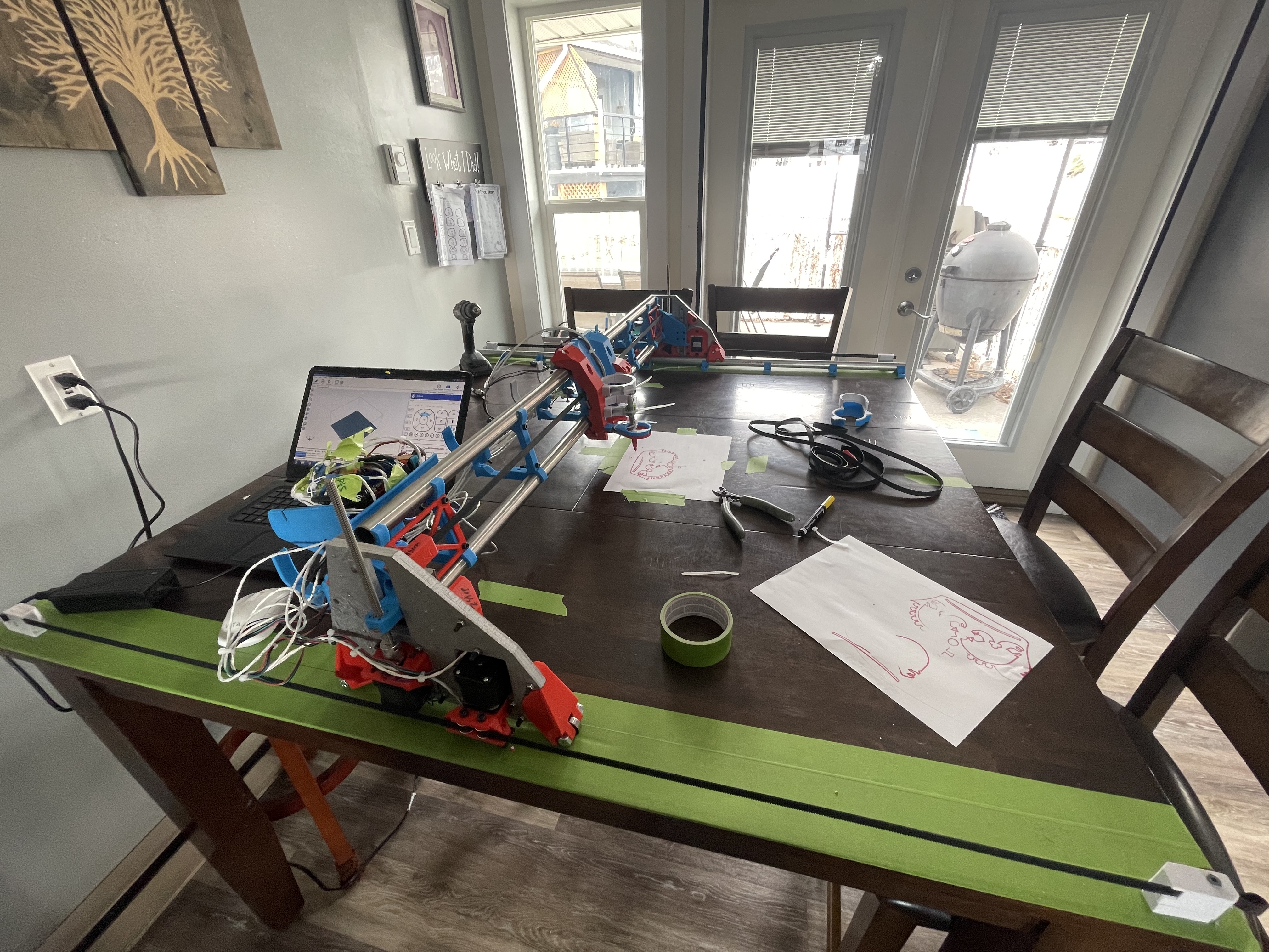
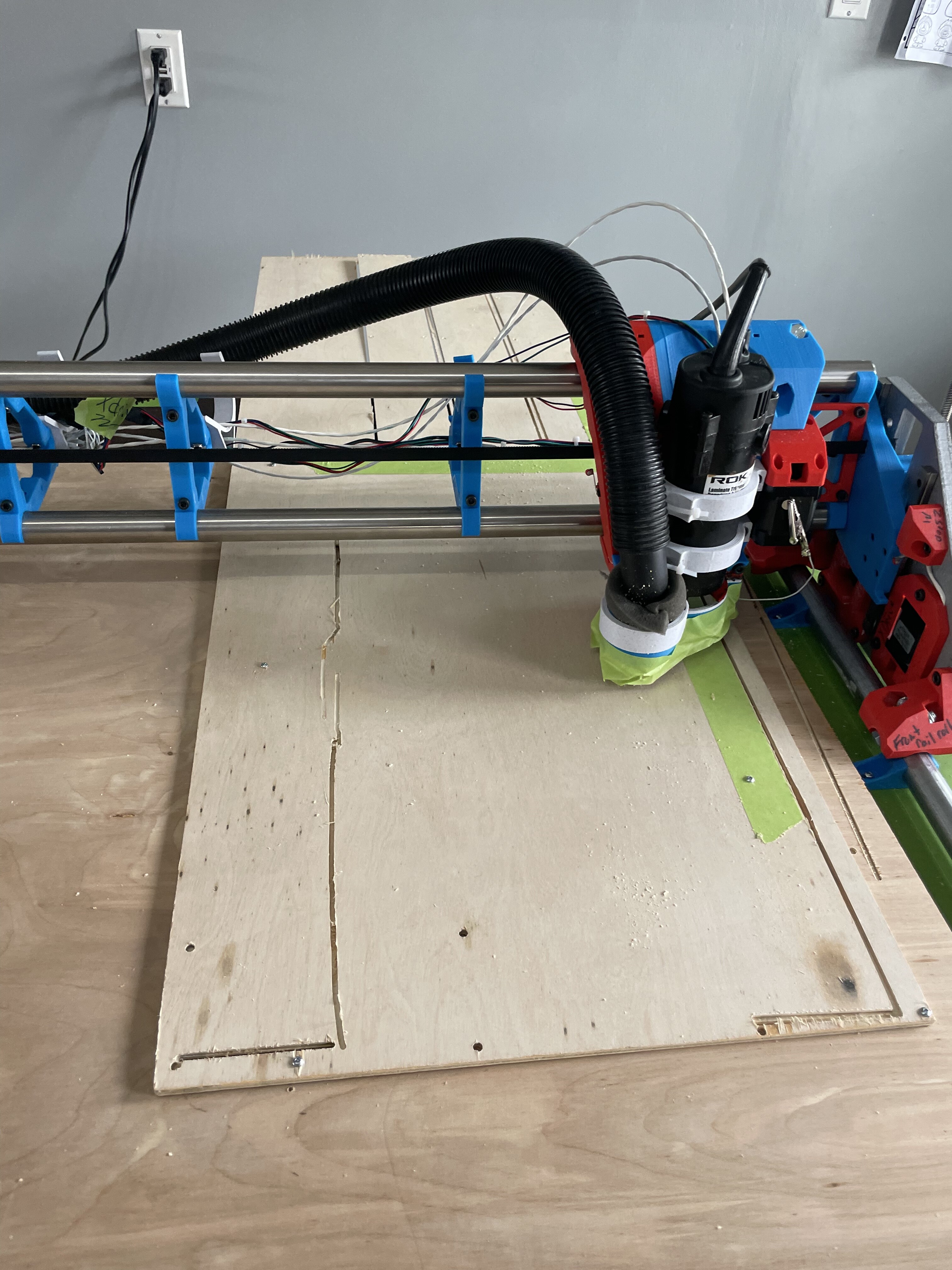
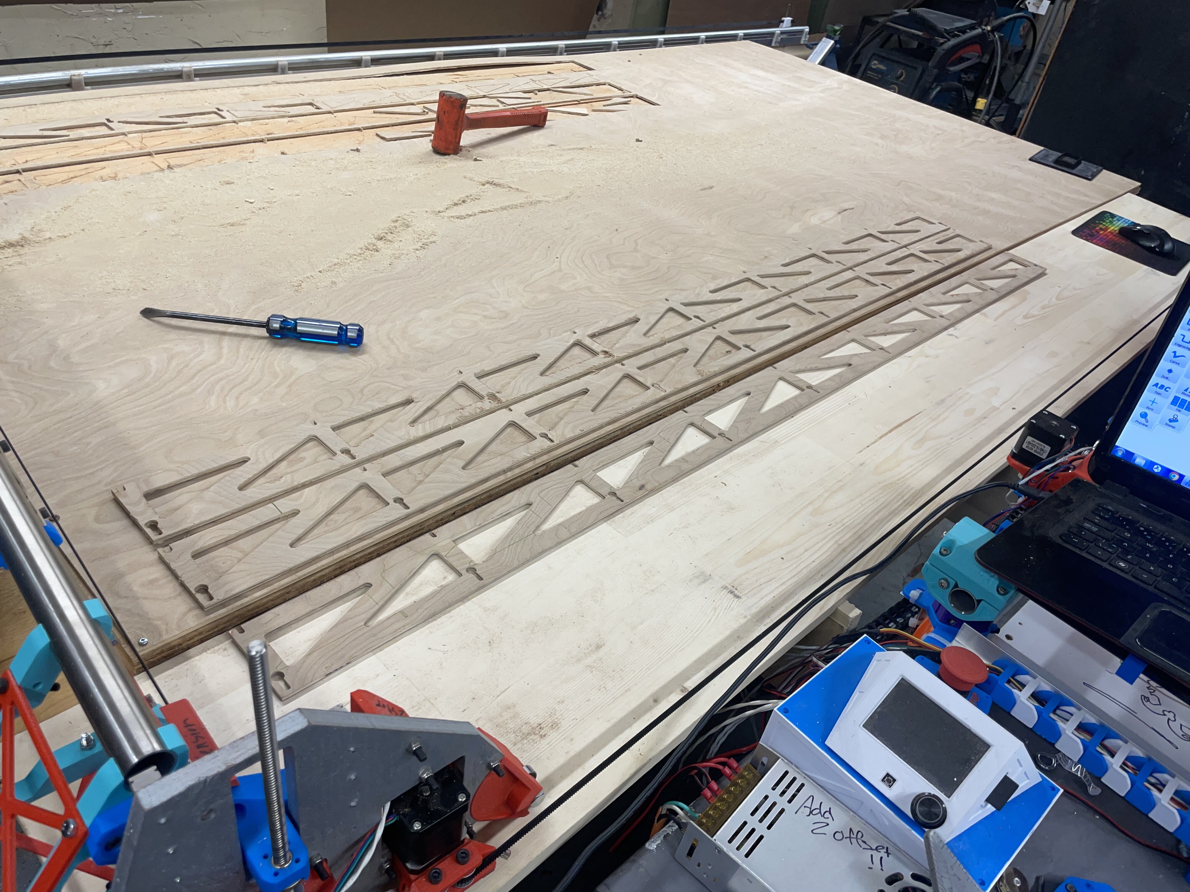
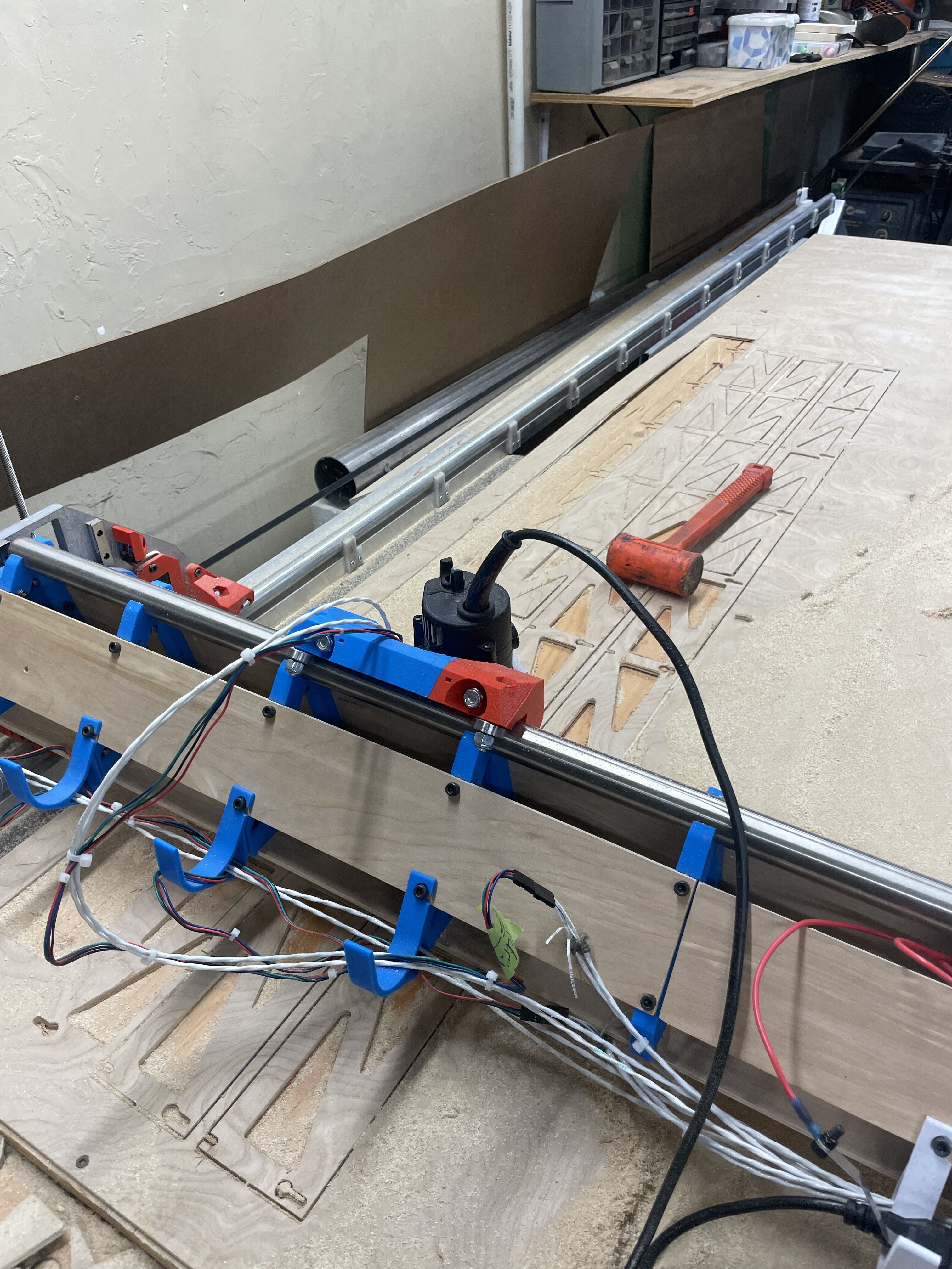
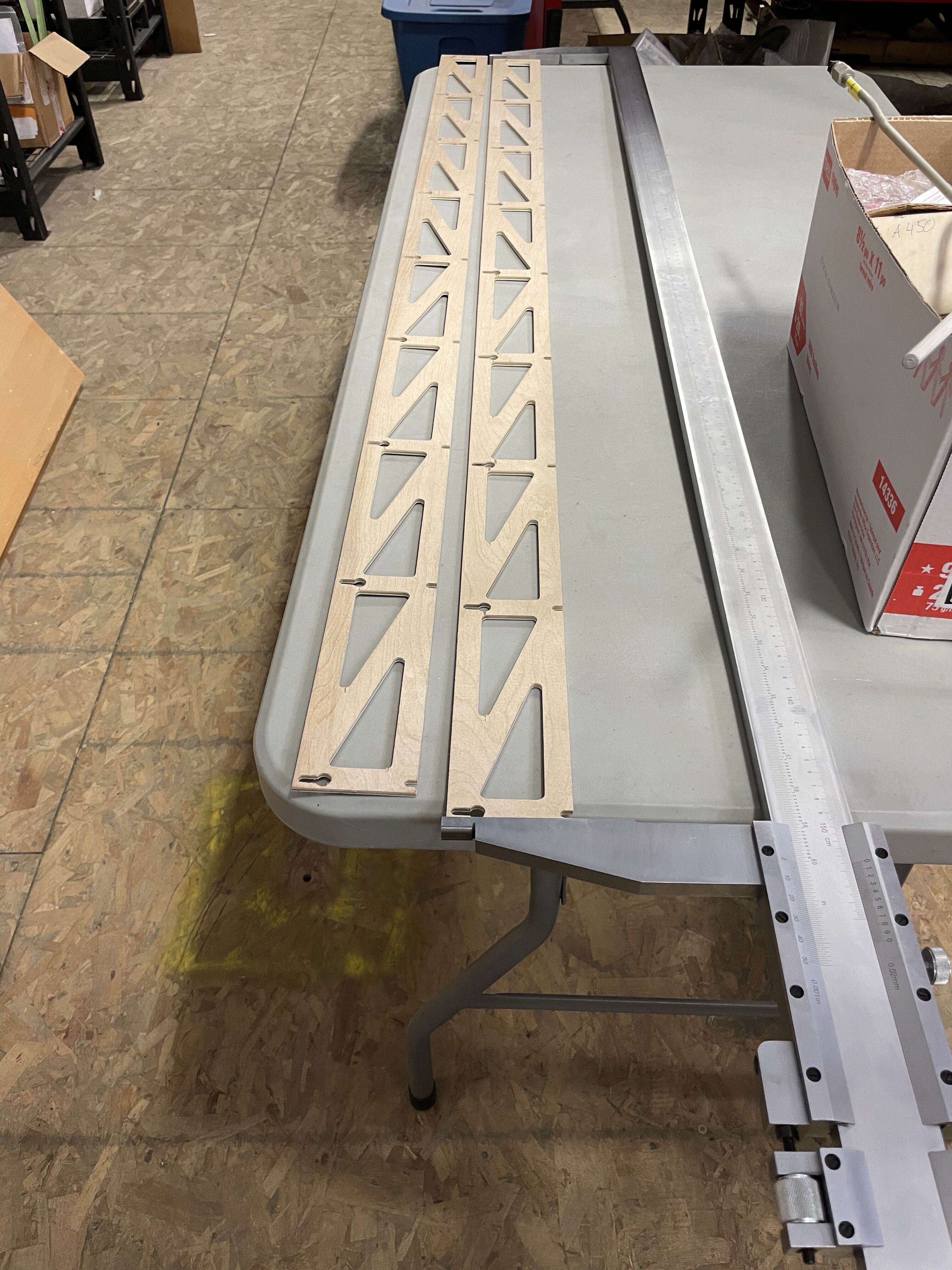
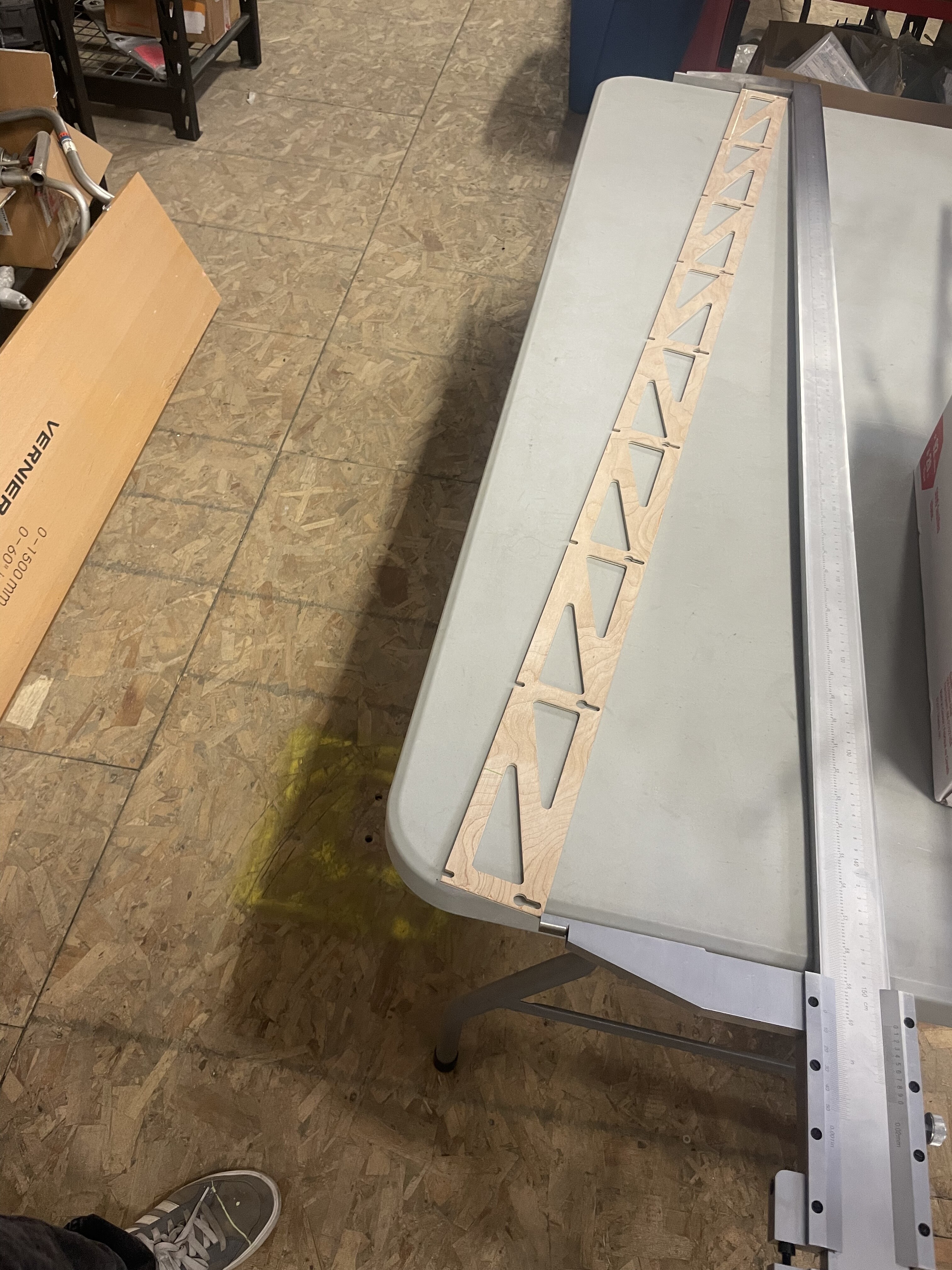
Well I think I am going to be at proper width here soon.
I had some issues with cutting depth as I use 3mm instead of about 5.5mm so I had to do some odd things with using zstop so I could go deeper. I had to command a z lower at the 0,0 and then I zprobed it there with a thicker offset.
And here I am sanding lol.
Next one I cut I will fix it.
4 Likes
Ok I just made my file again using Ryan’s awesome parametric calculator. It appears I cut mine at 1526 for some reason.
Anyways my question is after re reading some great info on here.
Is it a thing to do finish cuts on your struts?
I added them in this time doing 6mm total DOC with 3mm increments(z)
And just selected 1/8th bit and left it at zero so it would do a 5% finish pass by default IIRC. I only did this for the outside “part” and figured it didn’t need to be super accurate for the triangle access holes. Is this going to be alright ?
1 Like
Looking good! Finishing pass certainly won’t hurt.
1 Like
Tried to do the nice finish pass. And it was going well and was my table out of whack and failed.
But it was taking 28 mins to finish so i could re start. At my no end stop 0,0
So I did a 6.2mm doc one pass at 18mms and it worked pretty well I was super impressed.
Cut it down to 12 mins a strut.
6 Likes
Nice!
1 Like
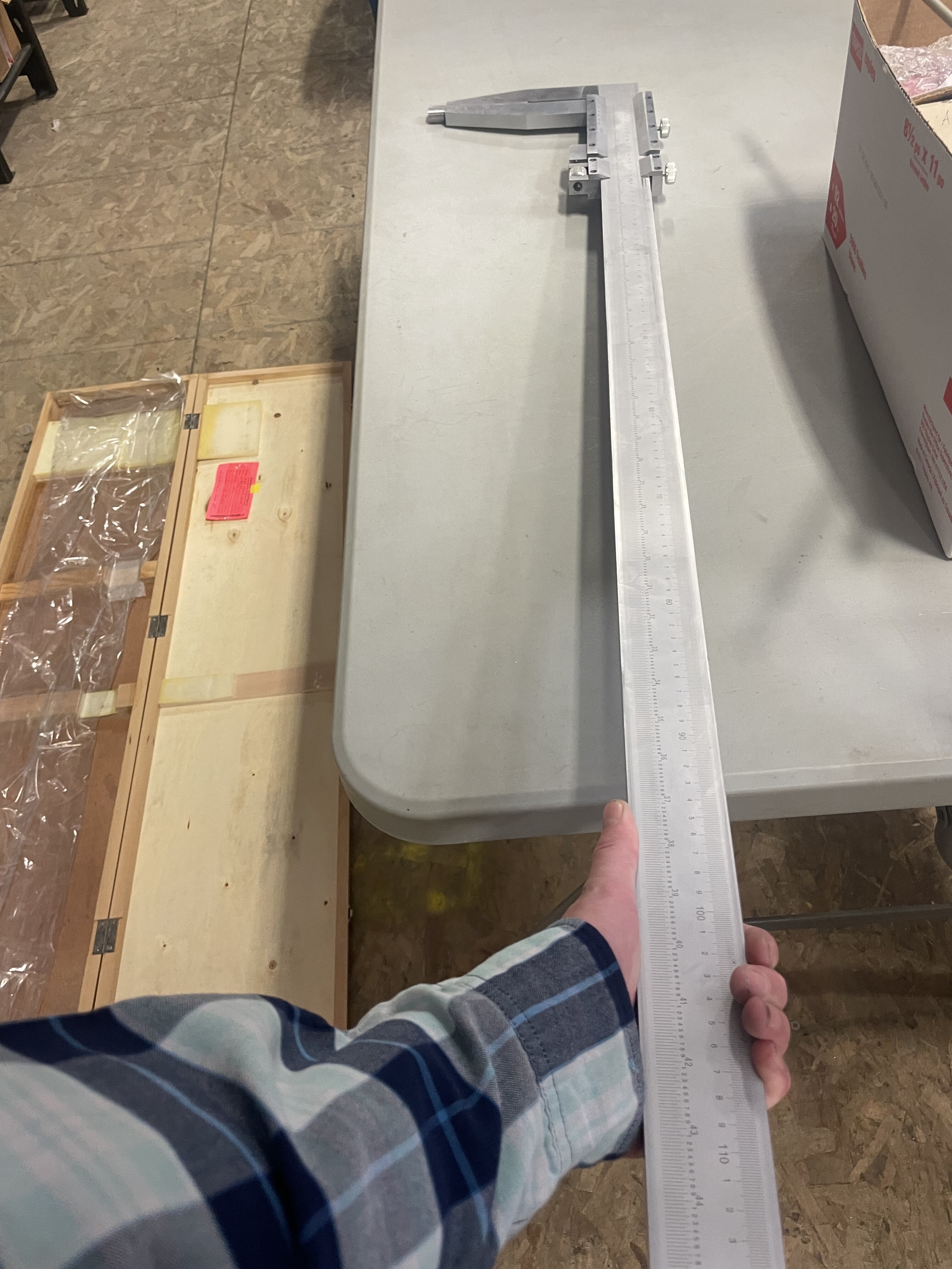
More funny than anything but I thought why not. And of course I now need larger calipers. Out of the range by 27mm
Still did it even tho they are out of calibration.
Supposed to be 1526mm but I never did finish pass etc.
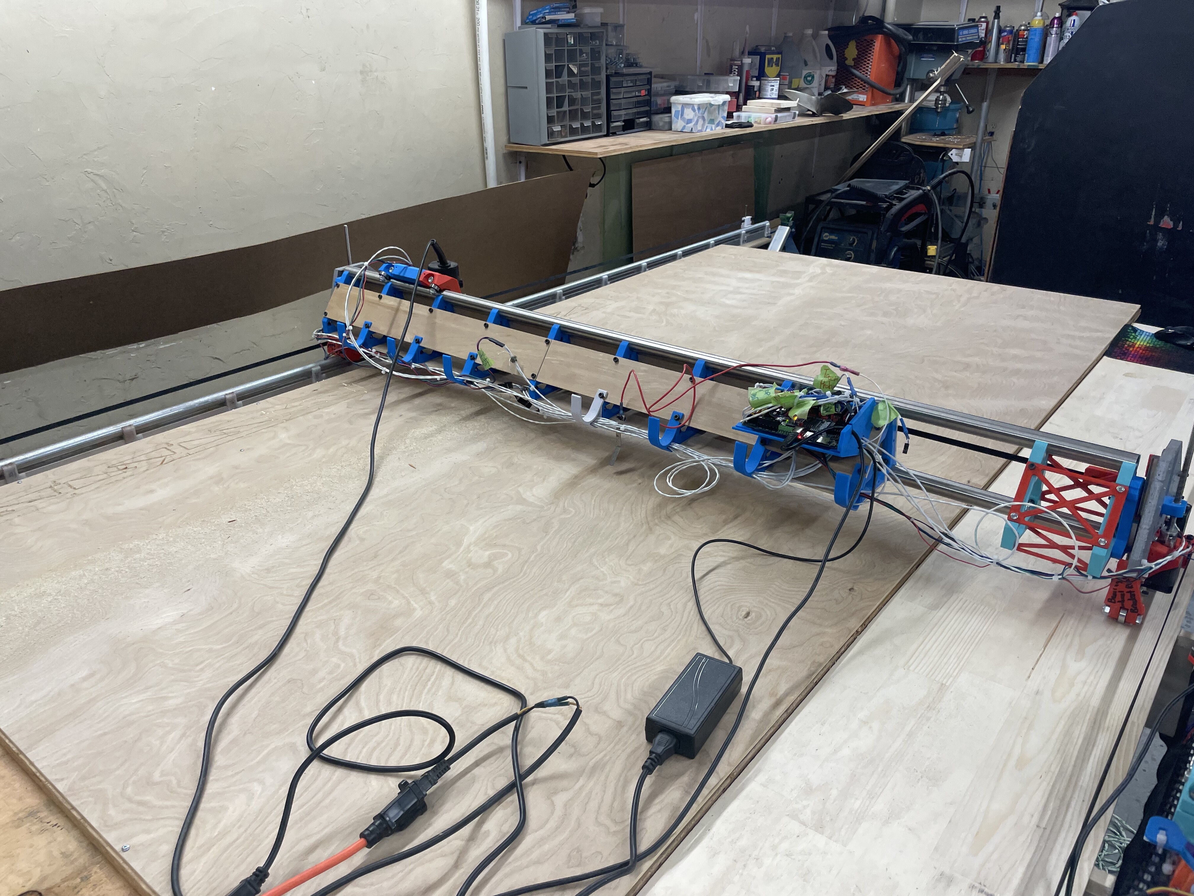
this machine surprises me all the time especially since I had a bit of a wonky situation I think due to my crappy temp struts. As you can see things are messed up in all kinds of places. It’s like a train wreck that still rides true. What a amazing design. All of these miss aligns are my doing and I will fix them once I get the struts done and mounted.
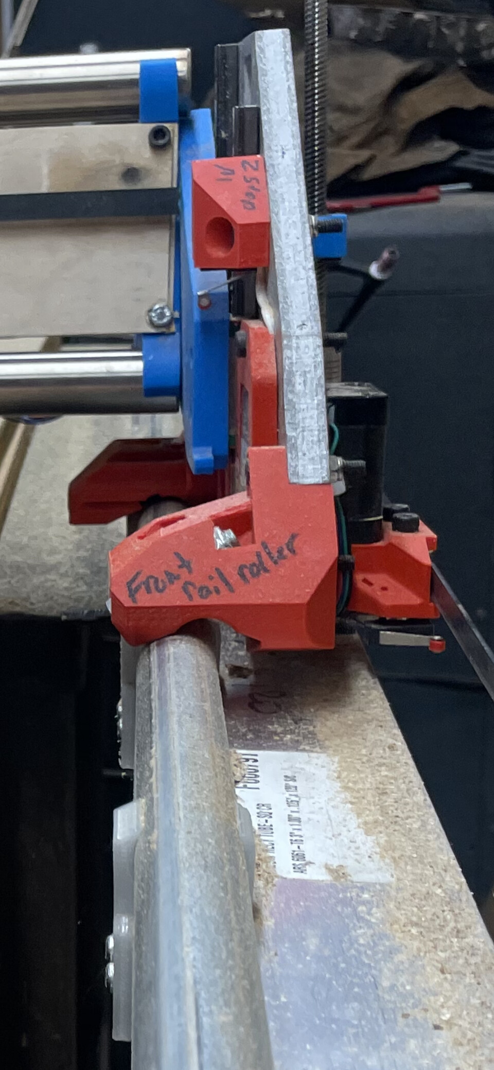
After all that I think I mixed up my measurements lol
5 Likes