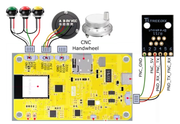
Hey folks! I just finished my CYD Pendant and I’ve come across a couple of posts on the TX/RX connections being incorrect. Is anyone able to confirm that on the RJ12 connector, that Pin 4 is TX and Pin 5 is RX? I just want to verify I’ve got TX-RX and RX to TX before I button everything up.
Update, I’m still unclear on which is correct, but in reading throught the Jackpot 2 forum post, 690 posts, I came across, what I think, is the point of confusion I’ve been reading about.
The FluidNC Wiki page and the image in post# 465 of the Jackpot 2 page shows Pin 5 (RX) of the RJ12 connector on the JP2 board going to the pin next to GND (TX) on the CYD board. My CYD board has that pin labled as RX, and the pin next to the 5V line labled as TX. Is this just a variation in board Manufacturers, or am I just more wacked in the head than I already thought?
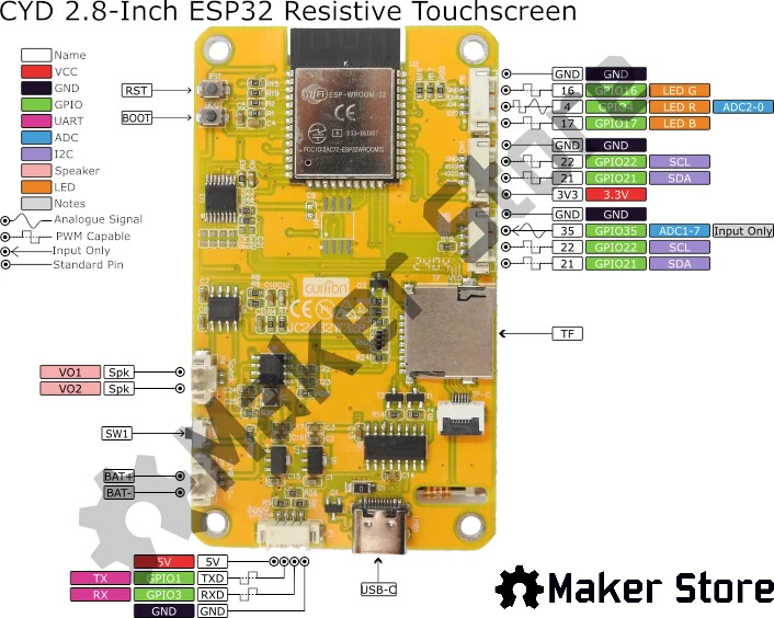
Wondering if other CYD board have the RX/TX swapped. The way I’m reading this though, is the yellow wire, labled as PND_TX_FNC_RX, means that wire goes from Pin 5, which is RX on the JP2/FNC to the TX point on the CYD board. The second pic show a PINOUT diagram which indicates the TX pin is actually the pin next to the 5V pin, not ground.
I actually don’t have the Pendant configured at all yet… That’s what I’m doing now. I was just wanting to verify I had the two wires correct, but as Dreyfus pointed out, if it doesn’t work, flip em.
The issue that I’m having in my brain (One issue of many!) is that I’m unclear as to which pins on the RJ12 connector are assigned to which GPIO. I’m probably seriously overthinking this and it’s more obvious that the nose on my face, but I just am not seeing it clearly for some reason.
Well, It’s working. It appears that the diagram in the FluidNC Wiki that shows Pin 5 on the RJ12 going to the CYD pin next to GND and Pin 4 going to the CYD pin next to 5V, is CORRECT. At least in reference to the CYD board I have. I have an alarm, but at least it’s connected. I believe the Alarm is due to not having a limit switch on my Z axis. Heading down that path now!! The stenciling on my CYD board shows that the pins are +5V, TX, RX, GND… The diagram on the wiki shows Pin 5 on RJ going to the RX on the CYD. It’s working in this configuration, so I think the labeling on the board is backwards. Nothing is ever simple!
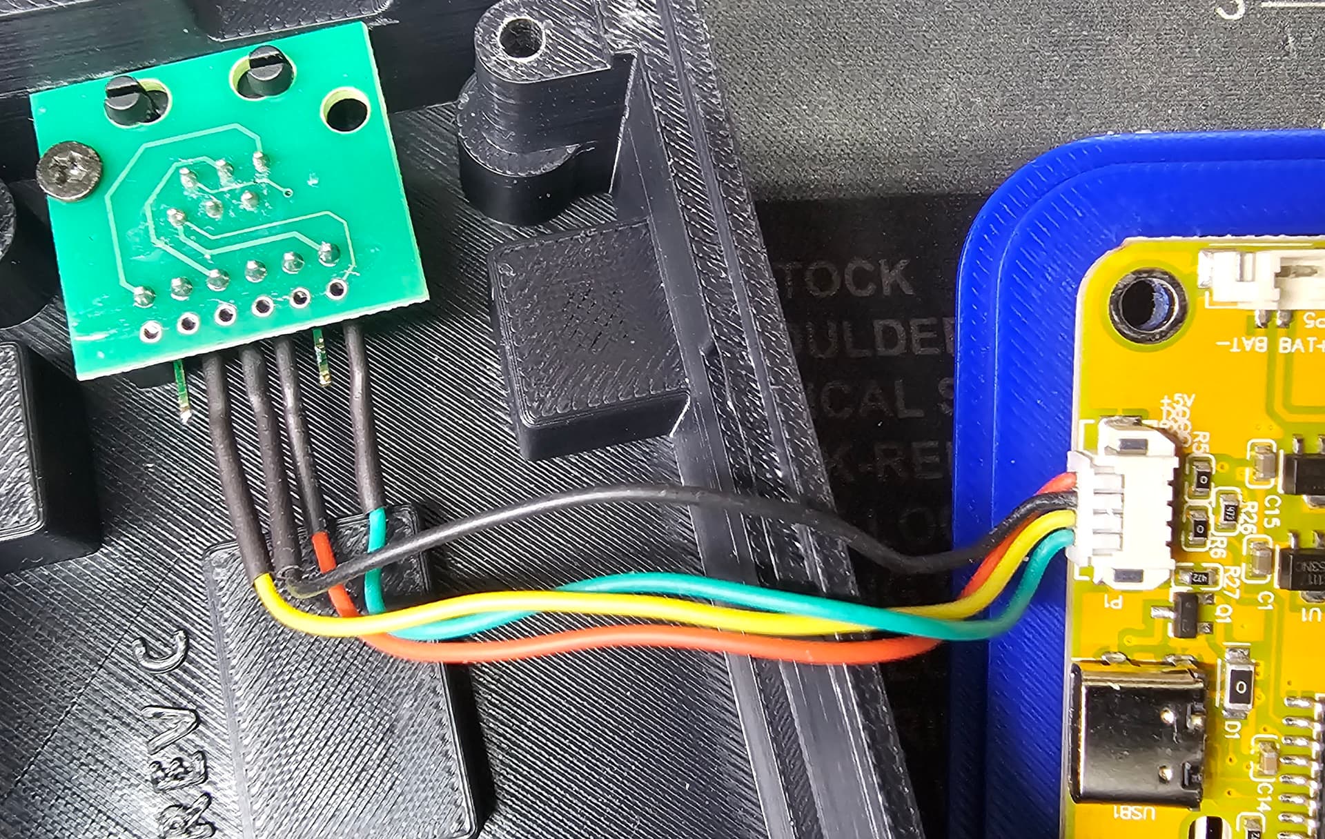
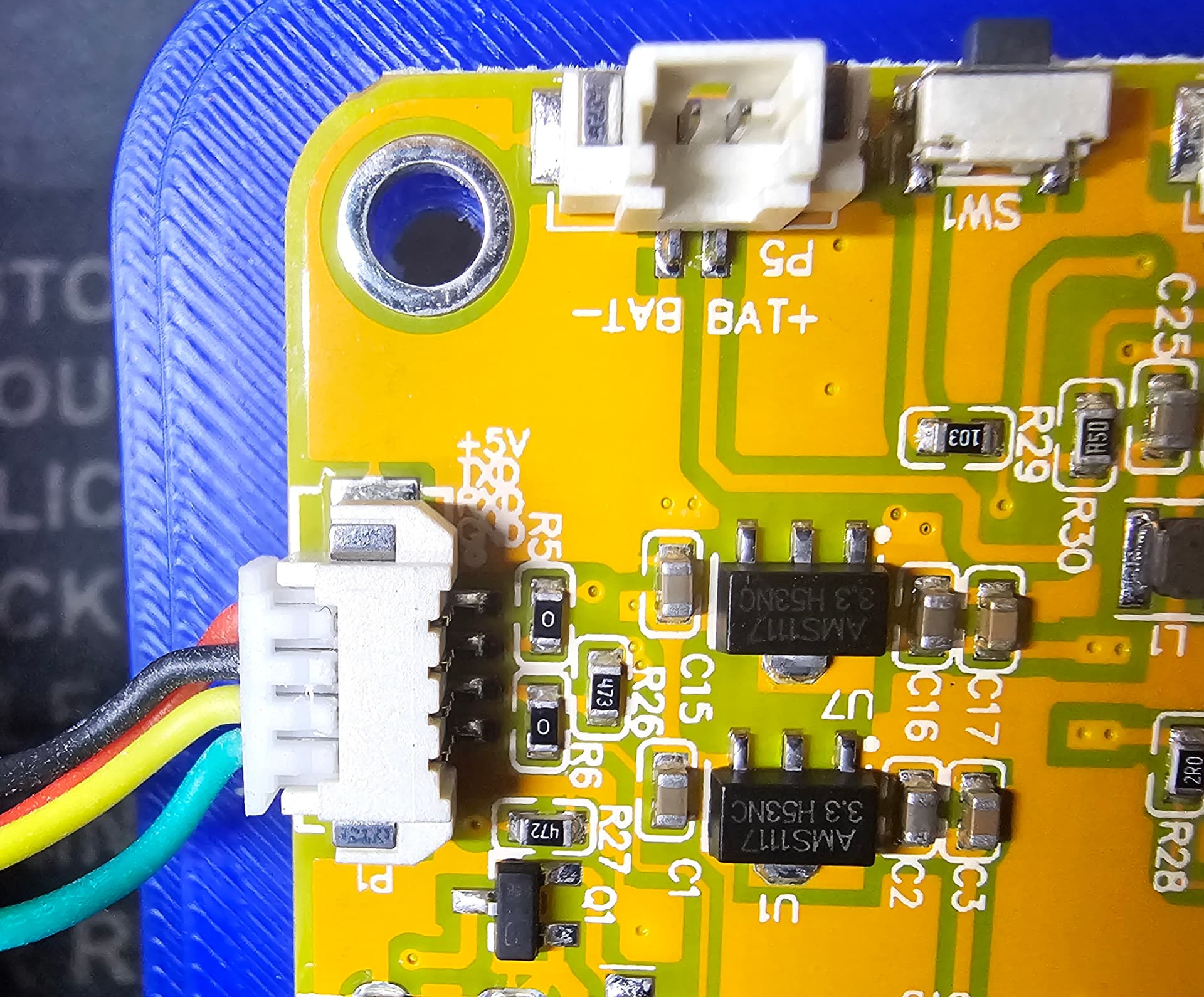
Pics below of my connections. Pendant is connected like this.
Didn’t mean to make extra work for ya Ryan. I still have vivid memories of all the weird shit I dumped on you guys about 5-6 years ago when I built my Burly. Archim 1 board, had some WEIRD stuff!
Glad it’s working. I’m playing with Ryan’s CYD design, except I’m going to modify both of mine to include a tiny DCDC converter to take VMOT power down to 5V. I think this is a slightly better approach to pendant power than a long 5V run.
I’ve got mine all dialed in now. I will go ahead and admit now that I nuked my first CYD unit by being lazy. I’d ordered a RJ12 breakout board from Amazon, but the ones I ordered didn’t have pin numbers labeled on the PCB. After a quick google search, I located Pin 1 on the female socket and, here’s where the laziness got me, “ASSUMED” that the Pin out at the rear of the board would be inline with the Pins in the jack. So I soldered the connector backwards to how it should have been. A super quick check with my meter, AFTERWARDS, showed all of the pins crossed. So my moment of laziness cost me $22, and 3 days of waiting for a new CYD. I put my meter on the RJ12 connector coming off the JP2 controller, and it turns out there was 24V on one of those pins, and that was one going to the RX pin. Afterwards, I plugged the CYD back into the USB-C on my laptop, and the LCD backlight came on, and that was that. I knew I shouldn’t have assumed and damn it if I didn’t do it anyway! ;(
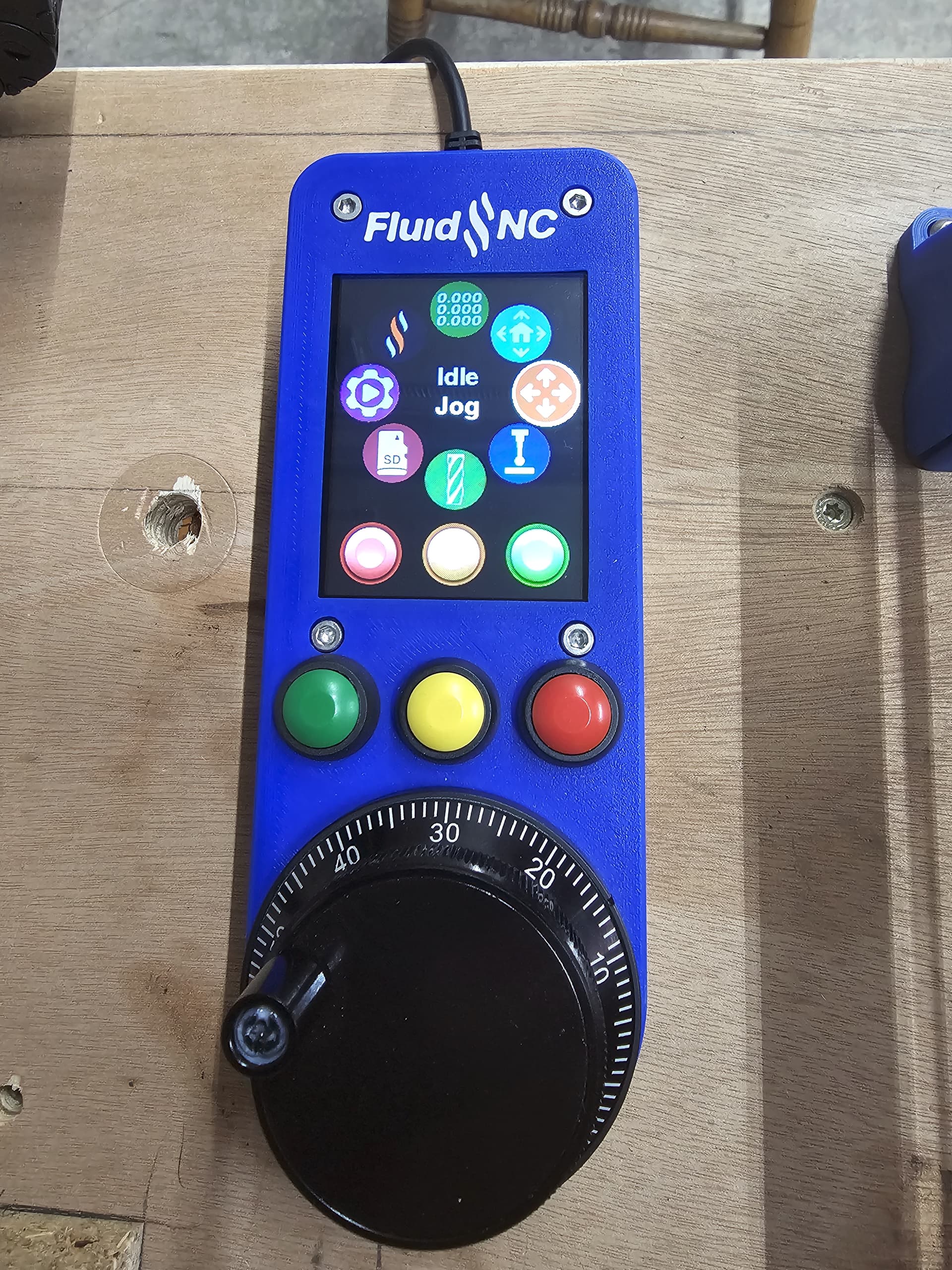
All is good now, another lesson learned. Here’s a pic of the completed controller.
It’s really cool how DIY stuff today does NOT look like the DIY stuff of even 10 years ago.