CAM - Spoil board newbie help please

Hi

I’m struggling a bit with making my spoil board file.

I have my MPCNC working perfectly and have created lots of drawings and basic engravings by exporting DXF files into ESTLCAM.

I have spent a while trying to make a file for a grid of holes, but have had no success. I have managed to create a model of the hole I want in tinkercad but have no idea how to export it properly - I’ve even put it into Fusion 360 but that seems even more complicated. Any file I’ve exported and converted to DXF doesn’t seem to be recognised by ESTLCAM. Can someone help? Can this be achieved in Tinkercad? I’ve used it a lot for 3d printing. Any of the free CAM programs seem clunky and non-intuitive.

All I want is some pocket holes in a 400x400 spoil board to hammer in a steel insert. I’ve downloaded Inkscape but it seems really complicated.

Screenshot 2020-07-20 at 10.07.25

Suggestions on the easiest way to achieve this and app to use would be appreciated. I have access to mac and PC.

Thanks

Make circles in a pattern with inkscape and make two pockets/holes in estlcam. (Sorry for being short, on cell phone)

2 Likes

Its not the model of the hole that you want to export it is the model of the board after the holes have been removed from the board. I don’t use tinkercad but can quite easily make a board 400x400 and ‘add’ a grid of your ‘hole’ model to that board and then subtract the ‘hole’ model from the ‘board’ model to leave a grid of holes in the board when using 123DDesign which I believe is from the same stable as tinkercad so should be quite similar in function (and less complicated than fusion360), and a google search will return videos on using the subtract function in tinkercad.


Estlcam accepts the .DXF exported from 123Ddesign ok.

1 Like

Fabulous. Thanks Mike - I’ll have a go.

Looks like 123DDesign is no longer available. It’s a shame tinkercad won’t export in a suitable format for ESTLCAM as I’ve easily managed managed this:

Looks like I’m going to spend ages trying to master Inkscape via youtube tutorials. Even just altering canvas size and drawing circles in a grid seems difficult.

123Ddesign is still available from many places, for example here
its just Autocad no longer support it.

Doesn’t ESTLCAM have a ‘tiling’ capability?

I think you can get away with only designing one hole and export that. Then in ESTLCAM you can tell it to tile the existing hole at certain offsets.

He talks about it here regarding another user’s issue:

I know that doesn’t help with getting the dxf to work.

In fusion 360, you model your hole. Then I typically create a new sketch on the face of whatever I want the dxf to contain. I don’t make any changes to that sketch, and I save it. Then you right-click on the sketch in the tree and select ‘save as dxf’.

I would keep a job like this in 2D. I would make the wider and smaller holes and then do a linear pattern to make the entire grid. Export that to estlcam. Then I would set up the toolpaths for one of them, picking different depths for the two holes. I would then use estlcam to do the pattern (as David suggested) to move those toolpaths to the other holes. I would add the chamfer myself with a drill bit.

Unless your spoil board and machine are perfectly flat, you will find that you won’t have exactly the right depth. So you might consider going a tad deeper.

2 Likes

More than one way to skin a cat huh :slight_smile:

Like Jeff said. AND if you want to be lazy about the chamfer, that could just be a third hole, middle size, middle depth. The chamfer probably doesn’t need to be very perfect fit a good fit.

1 Like

I might also consider just doing something very lazy with the CNC and marking the holes in the grid with a 1/8" drill hole about 2mm in, and then come back with a forstner bit and then then drill the main hole. The only reason I would do that with hand tools instead of the CNC is that I would be worried about the Z depth of the machine over the whole area. I also think a complete grid may not be necessary, and I would convince my lazy self to just do one row, one column, and one or two diagonals. :man_shrugging:

So, certainly more than one way to skin a cat. :cat:

Maybe I’m extra lazy, but the t nuts I had were nowhere near the top of a half inch board. I’d fire it up and crack a beer. If the z drops a little, it’s almost certain to be ok. If it wasn’t deep enough that means I get to zero z a little higher to force it deeper and get another beer.
I’m afraid we’ve gone from not having any option that gets this to work for him to having TOO many options to choose from!

Stack a few sheets of pegboard together as your spoilboard? Roll out some glue, and I bet they laminate quite nicely. :smiley:

Actually not so much. Don’t ask how I know…

It will be worth your while to learn a few things in Inkscape. It is a bit steep to start off which. So many features.

You can make a canvas the size of your usable space and save it as a document with the name “default.svg”. Set it up with the grids and dimensions that you would like.

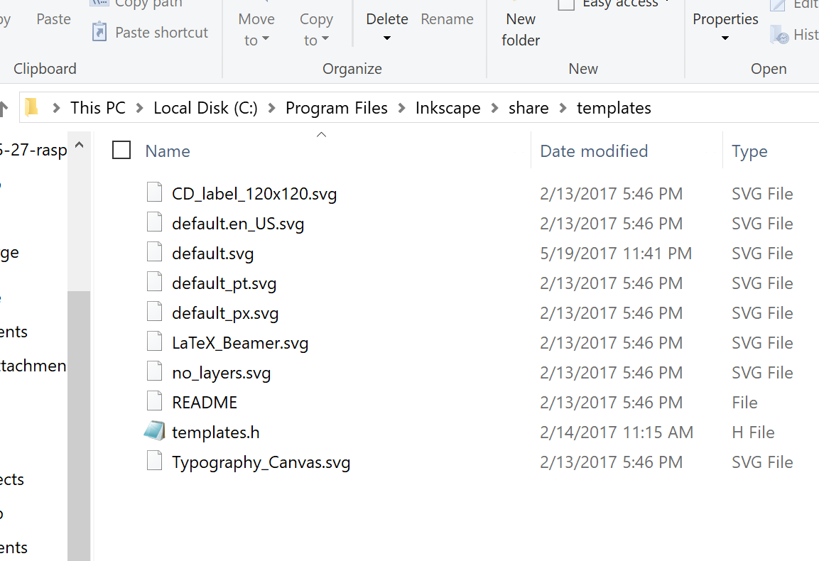
Open up file manager in administrator mode and copy that into the templates directory in Program Files > Inkscape > share > templates

Now every time you open Inkscape, your default template will be for your CNC. I have a couple templates set up, one for my laser and one for my MPCNC. I use metric in the CNC but Imperial in the laser (or used to. Now I have switched to all metric but haven’t updated my template.)

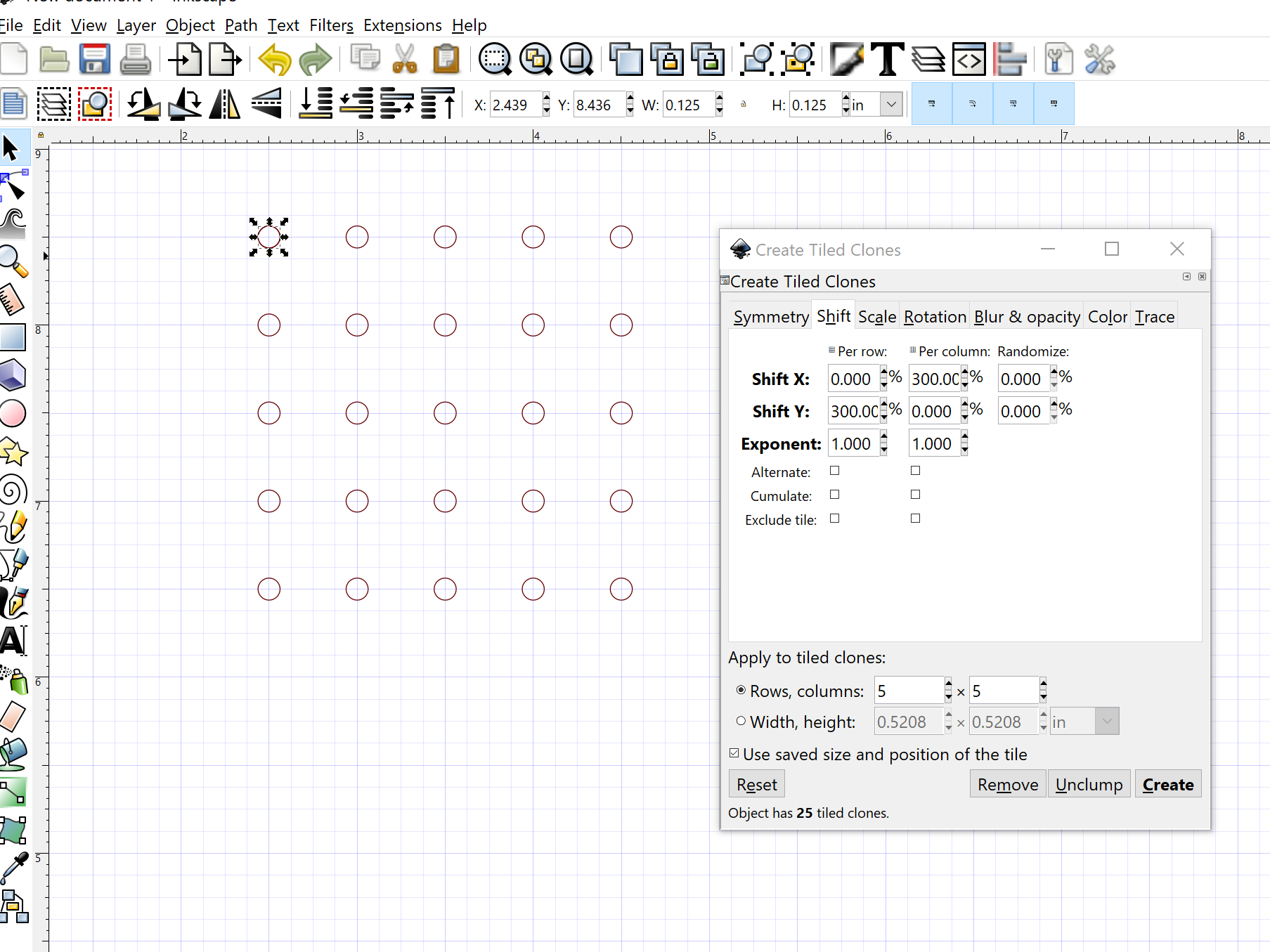
The other thing to learn about is the tiled clone tool which hangs out in the Edit menu. The way it uses percentages and messes with columns and rows and X and Y gets me a bit confused, but here is a setup that you can use to make an array of circles.

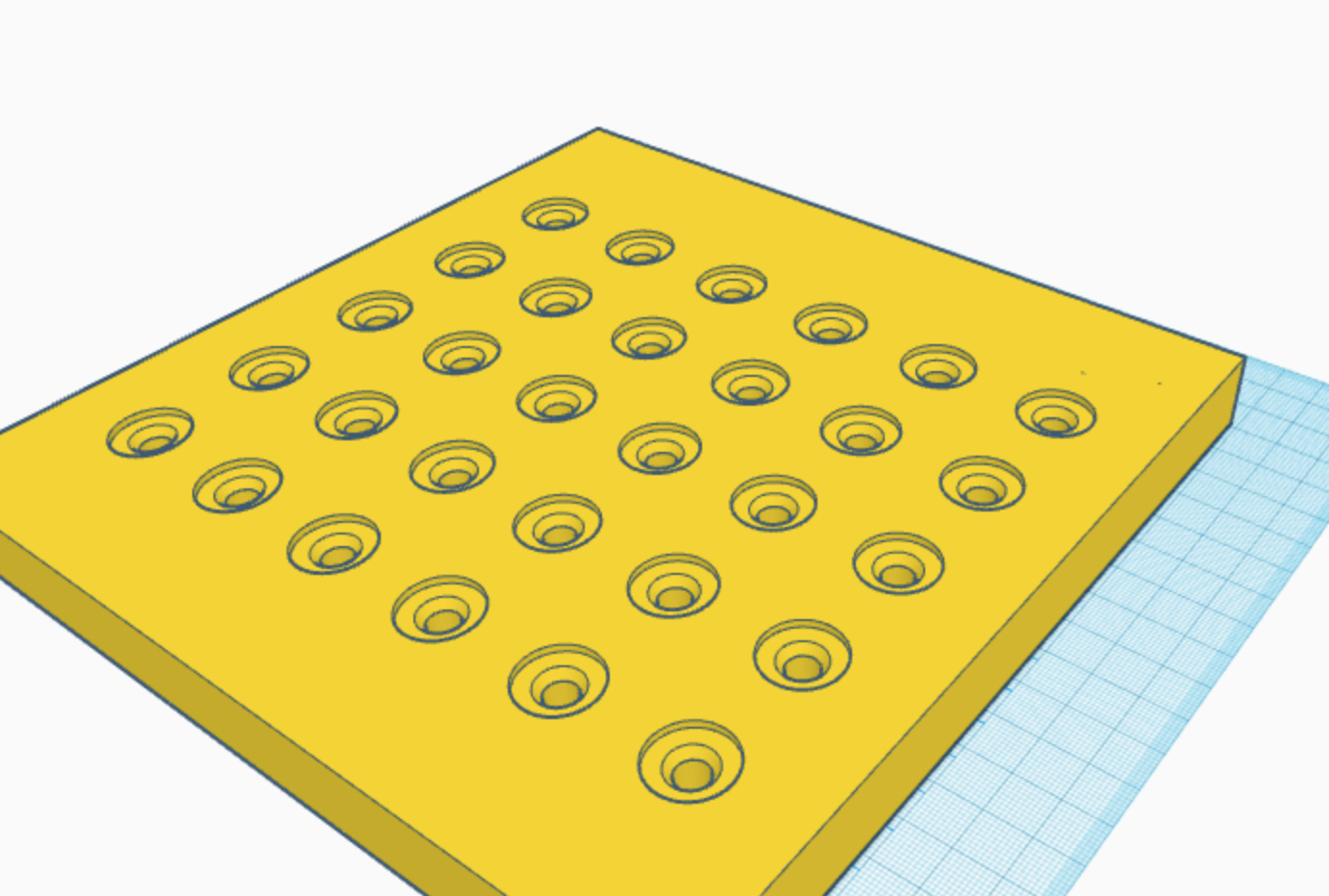
If you make a circle of .125". Then you can do a tile clone shifting each over and then down by 300%, you will get holes spaced exactly 0.5" apart.

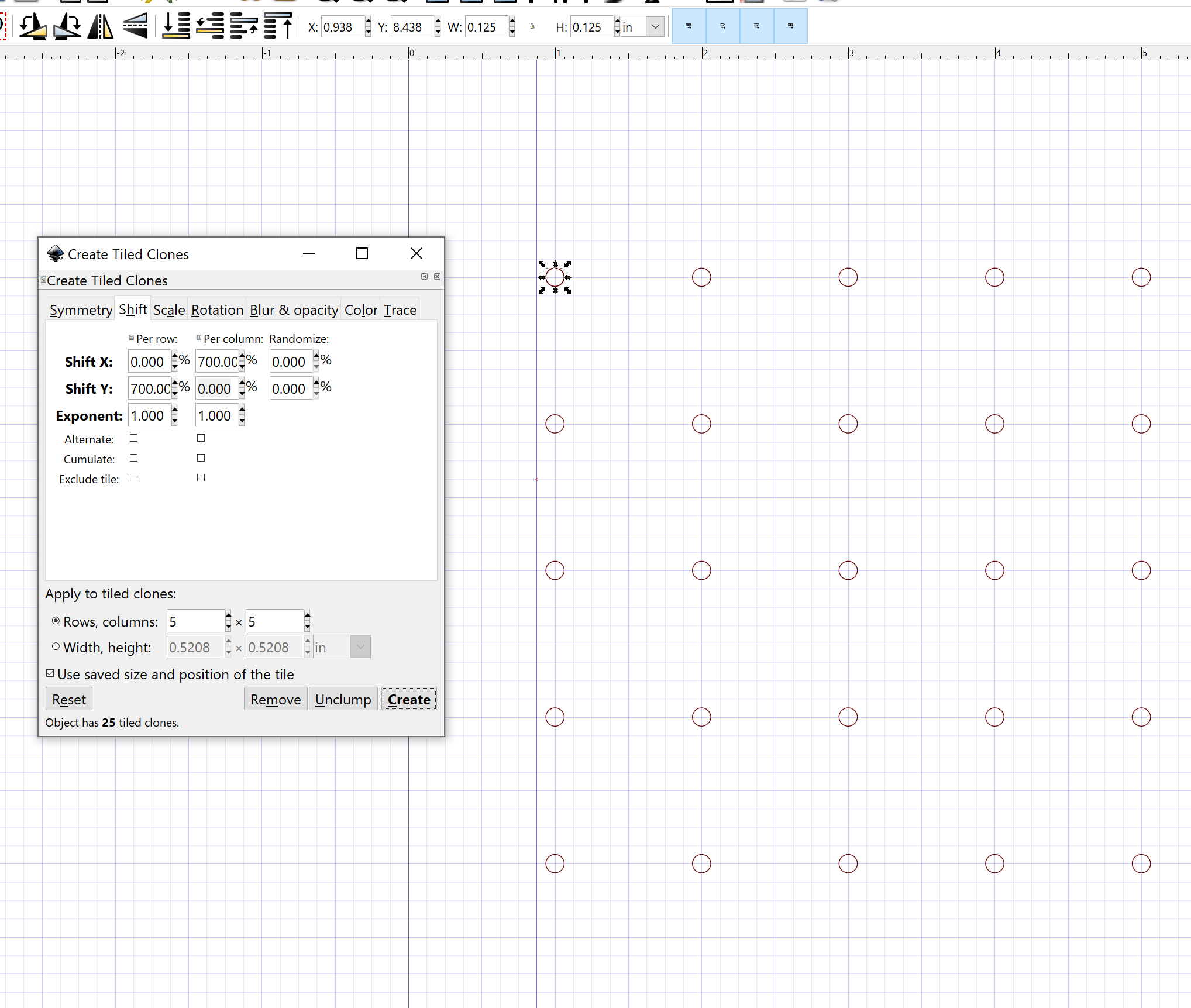
Make the holes 700% apart and they will be spaced 1"

Don’t forget to delete the extra clone that is on top of your original object. Make sure you unlink all the cloned circles to make them individual objects or you will get just one circle in the final design. Do that by selecting all and then Edit > Clone > Unlink clone

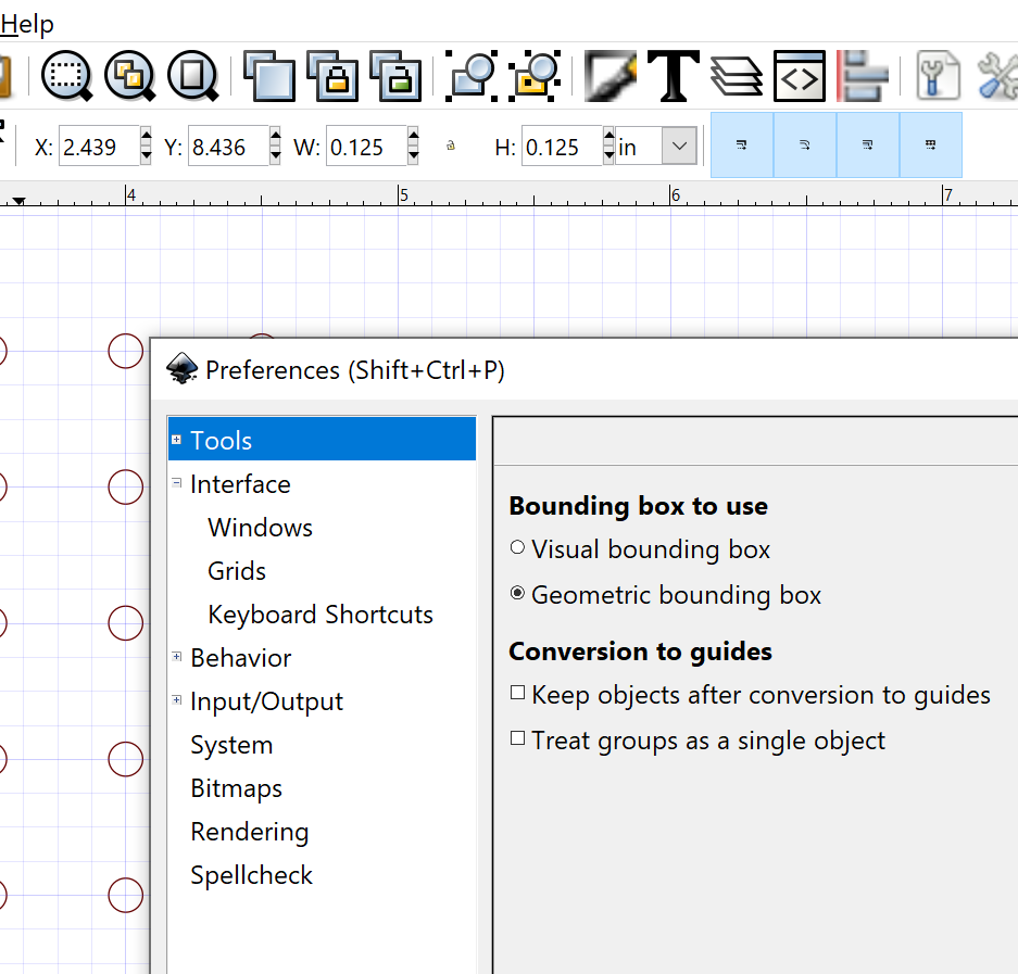
Make sure you are using geometric bounding box for measuring. That’s an obscure trip up that can through your measurements off. Found in Edit > Preferences > Tools What is going on is that measurement can either be from the center of each line or from the edge of each line so defining a 1" square can be done differently if your stroke width is wider or narrower.

The other way of doing holes is to make a bunch of them and do the align and distribute in the Object menu. Make all the holes you want and then put four of them at the corners of where you want the grid to be, then align and distribute. A little more complicated but great for when you are filling a known space.

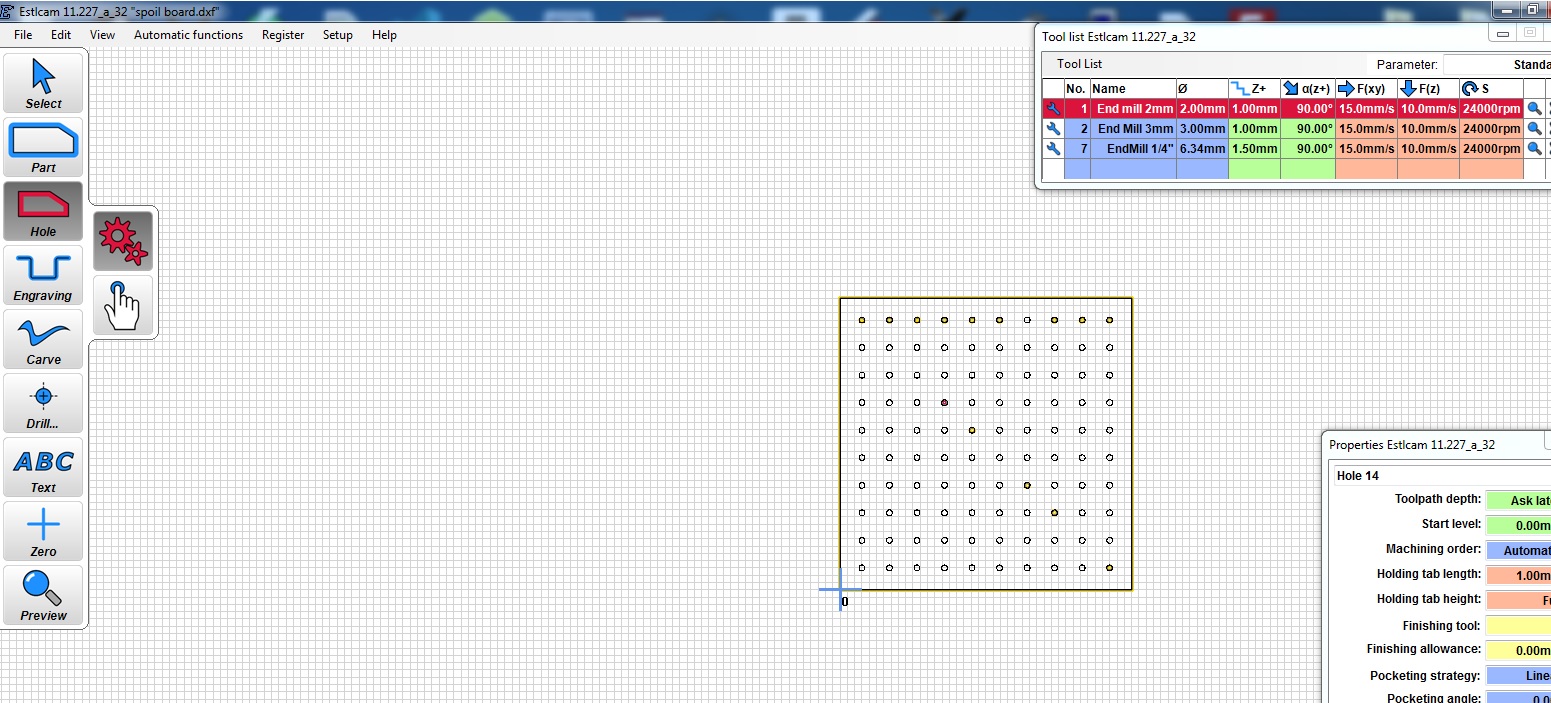
Oh, and this will give you a lot of holes to define toolpaths for. EstlCAM’s tiling function is much more efficient, but as noted, you can define all of them at once by selecting all the objects.

6 Likes

Very informative thank you

1 Like

Thanks all for spending the time to reply and especially for the steer on Inkscape. I’ll give it a go and post results :+1: