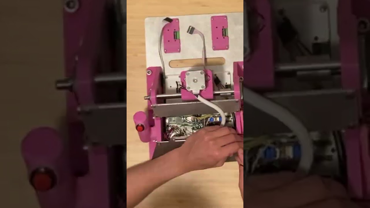
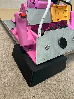
Lets see it!?!
^^^^ what he said ^^^^
Hahah doing me dirty Ryan. I’ll have another video in a sec… ![]()
YES!!!
Wait
Are seconds longer where you live? Lol
Yes hahahah different units around these parts. A penny for your patience:
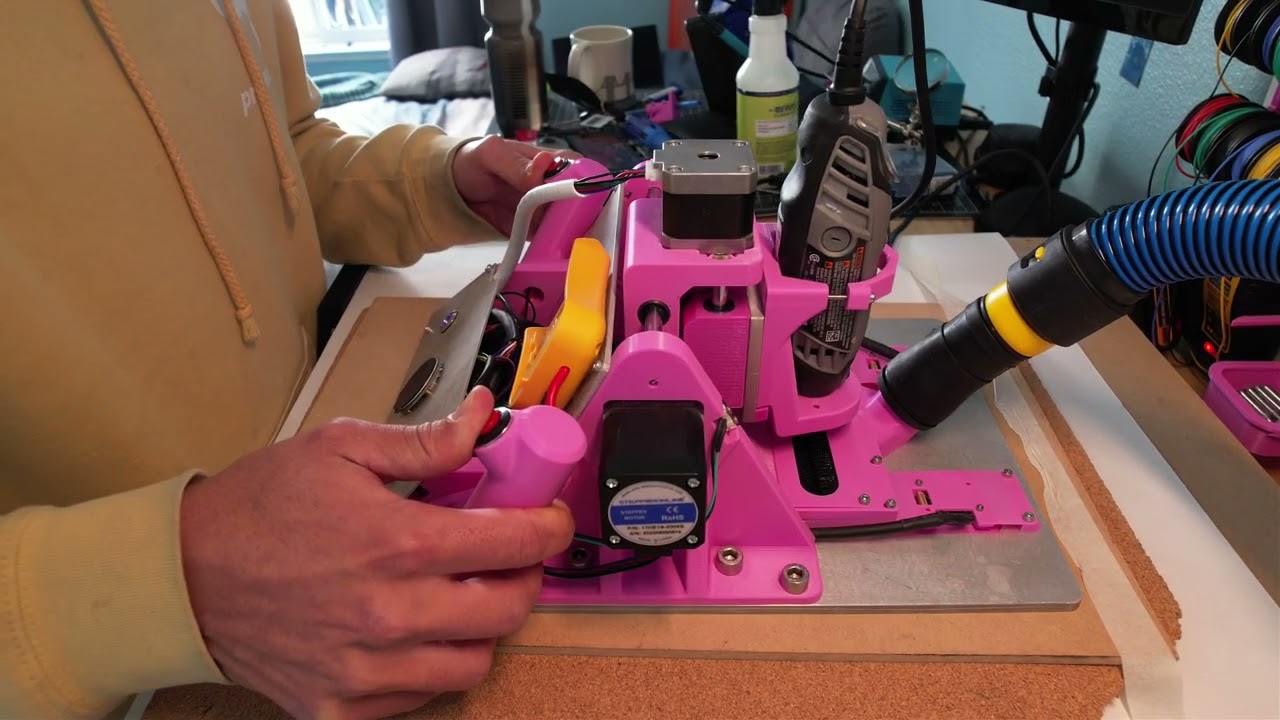
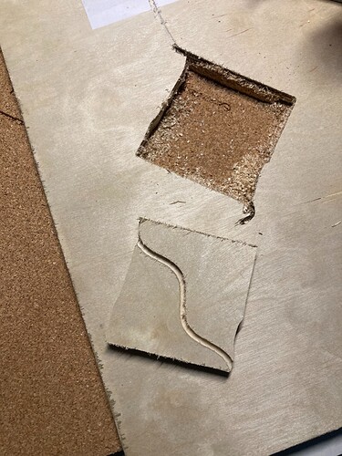
A few failed attempts here hahah. Realized after a couple trials that some dust got in the sensor (will have to figure out a more robust way to keep debris out of the lens). I can definitely feel the extra feedback force from the dremel with the thicker wood. The imperfections in the final cut are coming from the dremel having a mind of its own and the motors not being able to catch up in time. Might benefit from a more powerful router…?
See if your local big box has some small 2x2 squares of this stuff, https://www.homedepot.com/p/Owens-Corning-FOAMULAR-NGX-F-250-2-in-x-4-ft-x-8-ft-SSE-R-10-XPS-Rigid-Foam-Board-Insulation-52DDNGX/315197962
It is great for practice cuts, and using as a spoil board. Your current board might be adding some drag as well.
A bigger router will help but that dremel is pretty good for validating your code I would imagine.
Super exciting to see it cutting wood after watching so many pen drawings.
I wonder about maybe waxing the bottom of the aluminum plate or using something more slippery like HDPE. Does the bottom of that plate have a bevel or it is rounded?
It also seems like multiple passes with a shallower DOC might help. This seems to be crossing into more traditional CNC territory where feeds and speeds come into play. Interesting to think about in this context.
That is exactly how I feel about it. It is so different, I keep wondering if the workflow should or can be the same.
If it was something milled you could add small air channels from the outer skirt to the inner work area so the vacuum is always keeping air flowing past the lenses. An HDPE skin is super easy to mill and like Jason said might give less motion resistance. Or a 3D printed base.
Super fun to think about the differences.
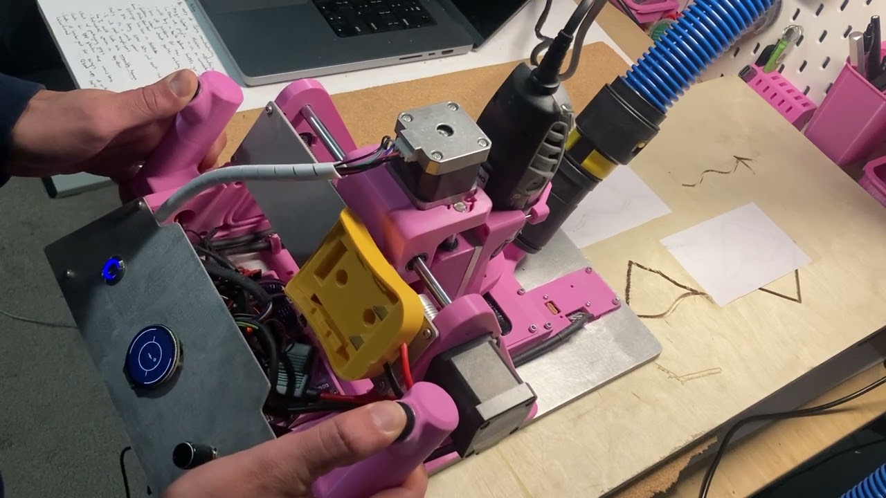
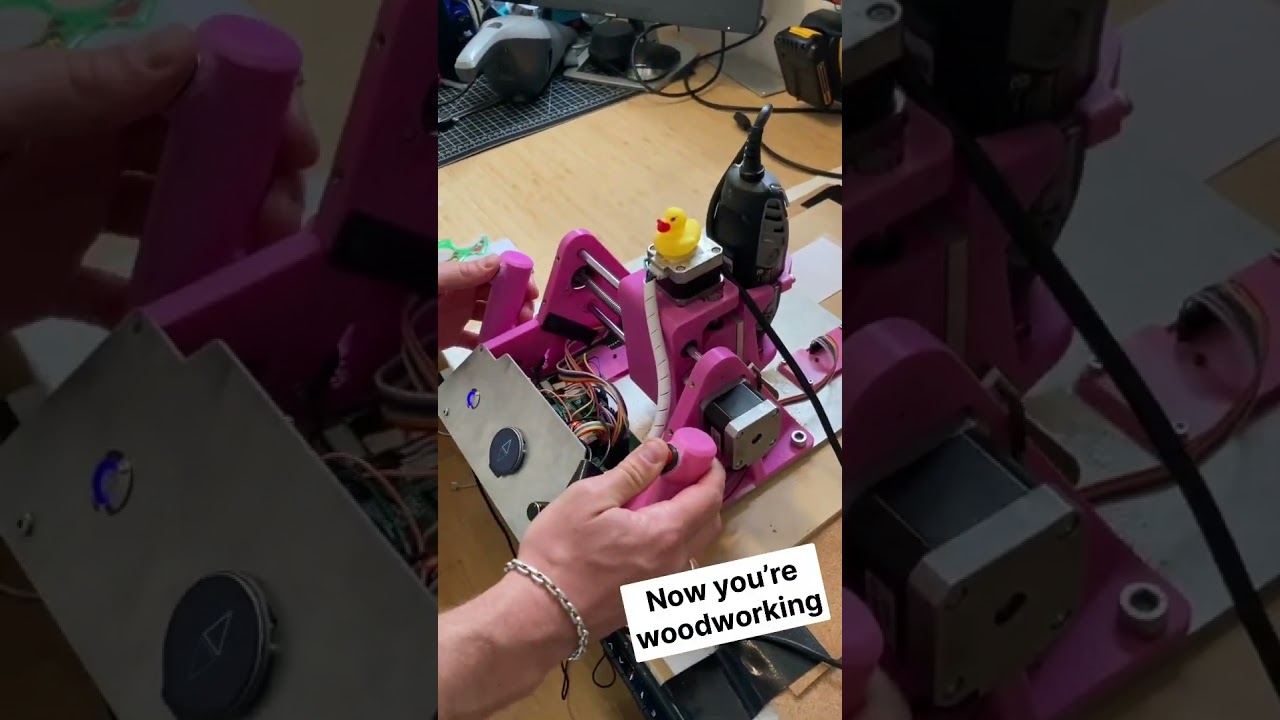
Demo of the current interface,
This demo and the straight line at the end kinda blew my mind, and I have actually tried it myself. I understand the first two, the third one really hits it home that it is not just moving left and right to correct.
Hahah totally. It’s so much more exhilarating to use it when it’s cutting than with the pen. You gotta give it a try sometime!
Hmm yeah I’ve thought about maybe using HDPE. The slipperyness of the base hasn’t really been any issue for me, though. It’s more so the resistance from the cutting tool when it’s doing its thang.
And yeah hahah I keep have the same thoughts. Multiple passes would definitely help with the cutting feasibility, but then you have to consider the potential drift with the sensors. With the current design, the further you go, the more possibility for inaccuracy, so you’re always trying to minimize this with your path planning. You would just need a consistent way to re-zero the machine in between passes. I’ve been testing this with a 3D printed bracket on the corner of the workpiece. This seems to work decently, but it could definitely be optimized to get more consistent results.
Ok yes! I have really been wanting to experiment with a 3D printed version of this. I’ve been flirting with the idea of routing part of the vacuum flow to the sensors and incorporating some sort of venturi to flip the flow and push air out of the sensor lens holes as well. That might just be me getting too deep into over-engineering day dreams though.
That will push debris into the lenses though right? Pull in fresh air from outside.
Have you done any long distance test to find a limit? That zeroing corner bracket seems easy enough honestly. Easier than a bunch of stickers.
Maybe just go full hovercraft.
That is definitely outside the box…and I love it.
I demand a hovercraft CNC.
Sensor drift? Easy, just compensate with atom interferometry in a quantum accelerometer ![]()
Yeahh, you’d have to have some sort of filter between the vacuum channel and the output.
It’s kind of tough to say an exact limit, because the drift just increases the longer the path is. It’s really how much accuracy you need - or how much slop you’re willing to accept - for your cut. I did do some testing real early on and found that there is about 0.1% accuracy relative to the length of cut. So if you do a 1m long cut, there would be 1mm of error. But it’s hard to say how robust that testing was. It could be worthwhile to do some more in that regard.
So valid! Can’t believe I haven’t thought of that.
12 days and no updates, videos, pictures…killing me smalls. I know you are up to something.
