Do you have a gummed up ball in your linear rail? X or Y? I was told to pull my linear rail carriages off and clean and lube them prior to putting them in service. of course I didn’t do it at first until one of them was kind of sticky. It is worth checking on.
Just to rule out a non-mechanical root cause- can you run your sliced model gcode through Arc Welder (or it’s now-integrated functions in PrusaSlicer) and do the circular print with an arc-optimized set of gcode?
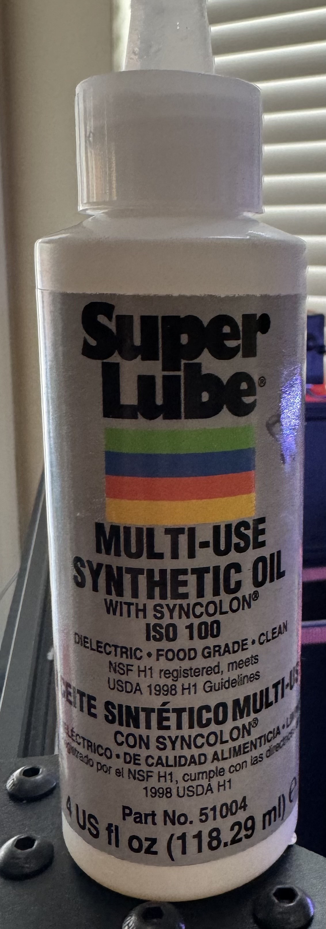
Did that. Disassembled the carriages, dumped the bearings out and flushed with rubbing alcohol. Re-lubed with super lube oil
2 Likes
I don’t think you can lube the belt in a way where the part that runs across the idlers is always lubed, but across the stepper is never lubed.
I don’t have it mapped out or anything, but a quick move from one corner to the other and I see at least 6 inches of overlap where idler belt crosses the stepper.
If lube is on the idler, I feel like it will eventually make it to the stepper pulley
1 Like
My slicer is already set to do the arc optimization.
It’s not unique to the rounded surfaces though. It does the same on rounded surfaces or long flat walls
Have you looked at those sections of gcode and verified that it is one long move and not many short linear moves? We’re trying to rule out a kinematics math problem (e.g. within the slicer or within Klipper)
Is there an issue with getting some lube on the toothed side of the belt? Part of the point of having a toothed belt is that it’s not as friction dependent as something like a V-belt.
tl;dr: The belt could be ‘sticking’ to a incorrectly cut toothed pulley, perhaps lubing the toothed side of the belt might help diagnose this, or replacing/swapping the toothed pulleys between A/B.
As a rough theory, if you had a pulley that had been cut wrong such that the slots were too narrow you could end up with a situation where the teeth of the belt get ‘wedged’ into the pulley and stick there. Then, as the pulley turns, the teeth of the belt would need to be pulled out of where they’re wedged. This would need force applied perpendicular to the pulley face, while all the force starts off as tangential. As the belt gets pulled around the pulley beyond where it would release in a frictionless environment the force vector will start to change until the perpendicular component is enough to pull the belt tooth out of the pulley. That effect would lead to the belt tension and belt path length changing as the pulley rotates, probably not by a lot in any ‘real’ cases, but perhaps by enough?
It would also somewhat explain why tightening the belt makes it better as the belt is likely fully wedged into the pulley at relatively low forces, so increasing the force doesn’t wedge the belt more but does mean that the perpendicular force to unwedge it builds faster relative to the angle of the pulley.
No idea if that’s a real effect or not, but it seems plausible, to me at least. One way to check this could be to try to lube the teeth on the belt. Something like graphite or PTFE spray could work for that, or even just light oil if you’ve got a belt you could consider sacrificial and you’re down to the last resort type options. Another diagnosis could be to disassemble and swap the A/B pulleys everywhere to see if the problem follows the pulleys or stays on A/B.
Personally, I think my money is on either a pulley that isn’t round or concentric, or a less likely possibility that it’s the belt sticking to the pulley.
1 Like
Here’s the Gcode for 1 layer of the box. 0% infill. 3 walls. each side is one long move
EXCLUDE_OBJECT_START NAME='Shape_Box'
G1 X150 Y184.91 F15000
G1 Z22.1 F3000
;TYPE:External perimeter
;WIDTH:0.629999
G1 F5857
G1 X115.09 Y150 E2.41005
G1 X150 Y115.09 E2.41005
G1 X184.91 Y150 E2.41005
G1 X167.455 Y167.455 E1.20502
G1 X150.064 Y184.846 E1.2006
G1 X150.064 Y184.846 F15000
G1 X150 Y184.058
;TYPE:Perimeter
;WIDTH:0.659999
G1 F5857
G1 X115.942 Y150 E2.47138
G1 X150 Y115.942 E2.47138
G1 X184.058 Y150 E2.47138
G1 X167.029 Y167.029 E1.23569
G1 X150.064 Y183.995 E1.23108
G1 X150.064 Y183.995 F15000
G1 X150 Y183.186
G1 F5857
G1 X116.814 Y150 E2.4081
G1 X150 Y116.814 E2.4081
G1 X183.186 Y150 E2.4081
G1 X166.593 Y166.593 E1.20405
G1 X150.064 Y183.122 E1.19941
EXCLUDE_OBJECT_END NAME='Shape_Box'
1 Like
I don’t know that it is definitely an issue, just questioning it because it seems like something that I wouldn’t normally do.
A quick search online and see some saying absolutely don’t do it.
I don’t have any graphite. Only super lube oil.
1 Like
OK, I’m pretty convinced you have a pulley/belt related impact as has been discussed above. All of the next steps would seem to involve swapping things between A/B and looking carefully at them for defects. Shafts bent, motors somehow misaligned, pulleys miscut, belts dancing up/down or getting stuck in teeth.
If you have a suitably sized square, you might also double check perpendicularity and parallel where appropriate (e.g. is the print head carriage actually perpendicular to the left and right rails? Are the belt paths really parallel or in line as appropriate all around?)
Yeah, normally I’d say that it shouldn’t be needed as well and if it fixed the issue, I think the answer would be not to keep the belt lubed but to find the offending pulley and replace it, so maybe that’s a saner path, given that it’s not really feasible to ‘unlube’ the belt, I guess.
If you’ve got a pencil, you’ve got graphite. Just scrubbing a pencil across a surface can sometimes help, otherwise I’ve used the graphite from a pencil sharpener or by whittling it with a craft knife before, in a pinch.
Ok, so new datapoint…
What I changed:
- Max accel set to 500
- Disabled Input Shaper
- Disabled Pressure Advance
- Loosened belt back to what should be the normal reasonable suggested tension (around 2.0 on the PFMakes belt gauge)
I printed it at the normal 110mm/s for the first 30 layers, then limited the speed using KlipperScreen down to 29mm/s the rest of the way
Pictures
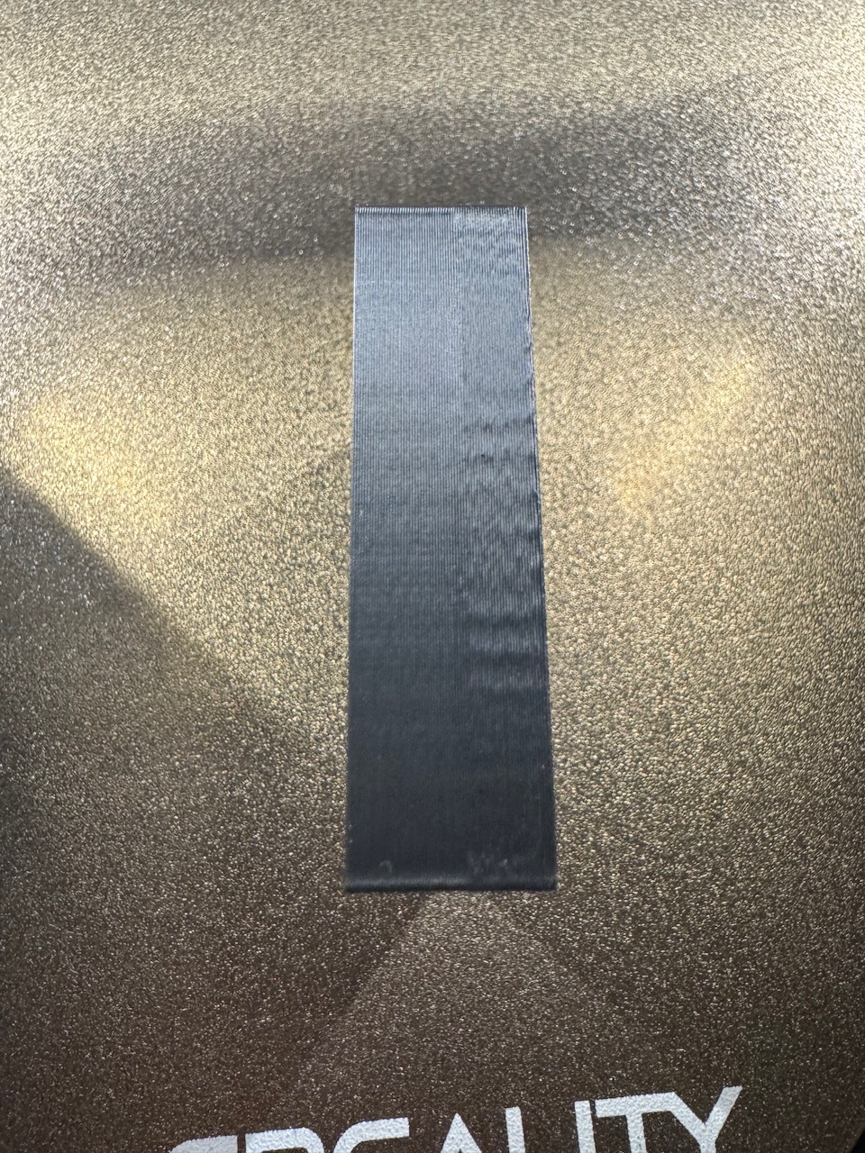
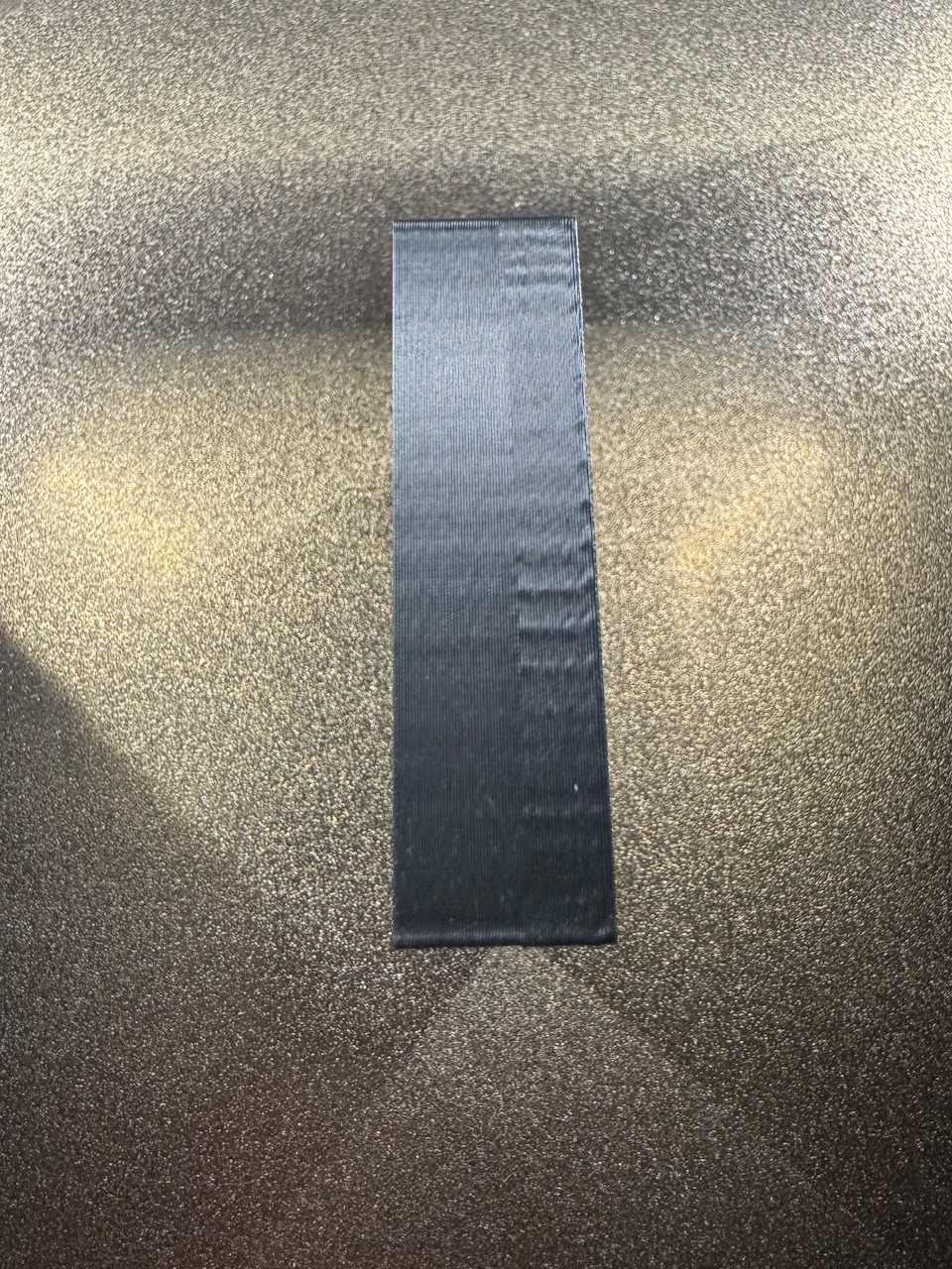
Observations
- While it normally only really showed on the B belt side, the pattern now shows almost equally on the A and side
- While the slower speed does look better, the pattern still appears even at 500 accel and 29 mm/s print speed.
1 Like
If you decide to try lube, AI suggested to consider something other than graphite…
![]()
As frustrating as this must be to work through. Personally appreciate this topic, seeing the steps taken, and ideas/thinking bouncing around from people.
Applications: “Gaskets, transfer belts, conveyor belts, …rubber moldings”
" GS 1100 is recommended for use on metal, plastics, glass and rubber."
Please, please double-check anything that that garbage fire tells you. It lies. I cannot count how many threads there are in technical forums laughing about how asking any of the AI assistants a technical question gets you a ‘truthy’ answer that’s misleading at best or plain wrong at worst.
2 Likes
Replacing all of the toothed hardware was going to be my next course of action before I started this thread, so I think I’ll go ahead and do that and see if that makes a difference
3 Likes
You have no idea……this is a thread of desperation lol
This has been 3-4 weeks of printing, changing, printing, disassembling, changing settings, printing,……
I had to stop for a couple days for my own sanity, then started this thread to see if it led me down a different path
@Jonathjon can vouch. He’s been trying to help me through it too
The flip side is that having 0 experience with a CoreXY printer, it helped me to learn a lot about it and what drives it
2 Likes
What is the spacing of the lines? You said it’s not the belt pitch but what is it exactly? Also is the pitch consistent around the round object?
That was measured with my calipers as accurately as I could. Hard to tell the exact beginning and end though.
Round lines are roughly the same
1 Like
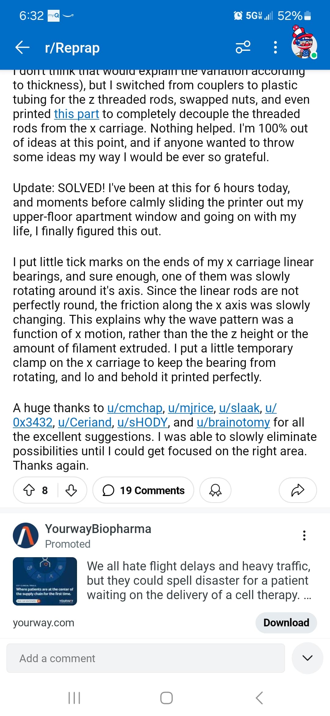
Want to send the link to that thread? I’d like to check it out
1 Like