Nope.
2 Likes
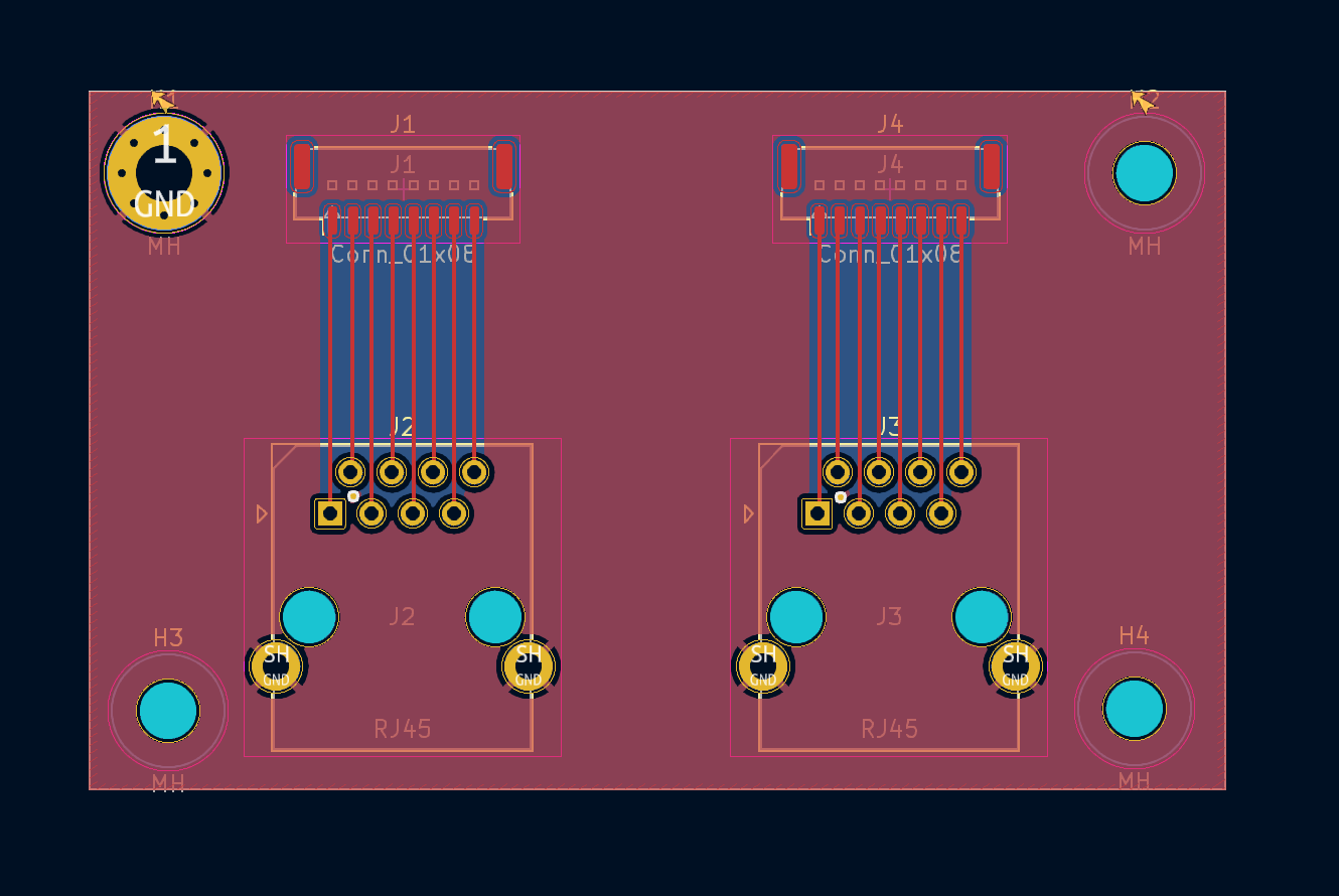
Yep, that’s the one. Ethernet patch cables are 1:1 pinned, just with a weird pinout for pairs vs pin number. You don’t have any pairs and won’t be testing for impedance/reflections/whatever so it just needs to be continuous and correctly pinned. Depending on MOQ you could also make it a single smaller board that handles just one end, that way if you only need 1 or 2 sets, getting a MOQ of 10 boards would give you 5 sets.
I also don’t worry about thermal reliefs anymore, personally. All my stuff is high-current and direct connected and we don’t see soldering issues anymore. I’d also add those mounting tabs on J1 and J4 to the ground plane without thermal reliefs for strength. Is there a PTH version of that J1/J4 header? If so, you might want to use that instead as it’s going to be going through hundreds/thousands of mate/unmate cycles. That said, it’s cheap enough that if you’ve got spares or need another it’s no drama. Alternatively, you could specify adding some epoxy/hot glue to the header to help with a bit more stability.
I’d also beef up those traces for strength. Make them the same thickness as the SMT pads and then neck them the minimum amount to get through the pads.
1 Like
Great tips.
Unfortunately not. It seems like JST only makes an SMD version. I’ll beef it up by removing the thermals and adding structural vias as suggested.
1 Like
Hi,
Excellent project. I’ve added it to my must do list but have a few others to finish first ![]()
If you want to test cables I would recommend just looping them back and streaming data over them. Just short pins 1&2, 3&4, 5&6, 7&8 on a socket and plug in one end of the cable.
Connect the other end to port pins on a micro, Teensy, Arduino, etc
If you drive out on pins 1,3,5,7 and receive on 2,4,6,8. Send an known pulse train and just look for it coming back in. You can do it directly from port pins with say 100 ohm in series with the outputs. If you drive all outputs at once with different pulse trains you can see if you are getting noise between lines.
You can then mechanically flex the cables and sockets to see if you have contact issues while streaming data.
You can also use USB / serial / 5V converters and do it straight from a PC. Depending on the chipset you can usually get 115200 baud with no problems sent as a 5v or 3v pulse train.
A bit painful to setup but if you truly want to “exercise” the cables I’ve found it’s the best way.
And I might stir the pot further by suggesting Flexprint PCB instead of cables?
These are often used in cameras, come with locking connectors and can even be shaped with folds or bends if you need to route them around corners. Haven’t priced them in some time, but may be cheaper than cable.
A nice metal box enclosing the back of your electronics may also go a long way to reducing noise. Its been along time since I worked in an EMC lab but bulk metal was always good!
Thank you, and I get the struggle!
I appreciate the tips and suggestions. Do you see any advantage to this method of shorting pins and debugging via microcontroller vs. the ethernet cable tester approach?
I steered clear of them just to allow for more flexibility with cable routing. I’d be interested to see if they’re cheaper, though. The cables are actually pretty easy to get very cheaply.
Hi,
Only if you are looking for noise or crosstalk issues and from your description and pictures of metal foil I was worried you had noise / crosstalk issues.
If you send a known message on one loop, you can check if any glitches are coupled onto the other loops by seeing if the other inputs change state.
You can then “walk” through each loop in turn checking the other inputs while it’s happening.
Similarly if you send “A” 10000 times, and don’t receive the “A” back 10000 times you can see if noise is corrupting the message and how often.
If your comms issues are most likely from bad crimps / connectors / solder joints then stick with a cable tester.
I’m trying to get KICAD running and bring in the schematics / PCB’s for a good look but traveling for work so my internet is limited this week.
If you are suffering from noise / crosstalk issues let me know, though I’ll probably just suggest a big metal box with all the cable shields connected to it ![]() and a capacitor to connect them to your DC ground.
and a capacitor to connect them to your DC ground.
Best Regards
Tim
Okok gotcha that makes sense. I was struggling with noise/crosstalk issues a while ago, but mainly from the stepper cables or when communicating with multiple sensors on the same SPI line. If I isolate one sensor/sensor cable, the only issues that really come up are from bad crimps or joints.
I think if I want to test the individual cables, the cable tester method still seems like the way to go. The noise/crosstalk issue is still something that should be addressed, but that’s seemingly systemic and applies more to the overall electronics design than routine QC.
I would certainly like to hear your feedback for the next PCB design!
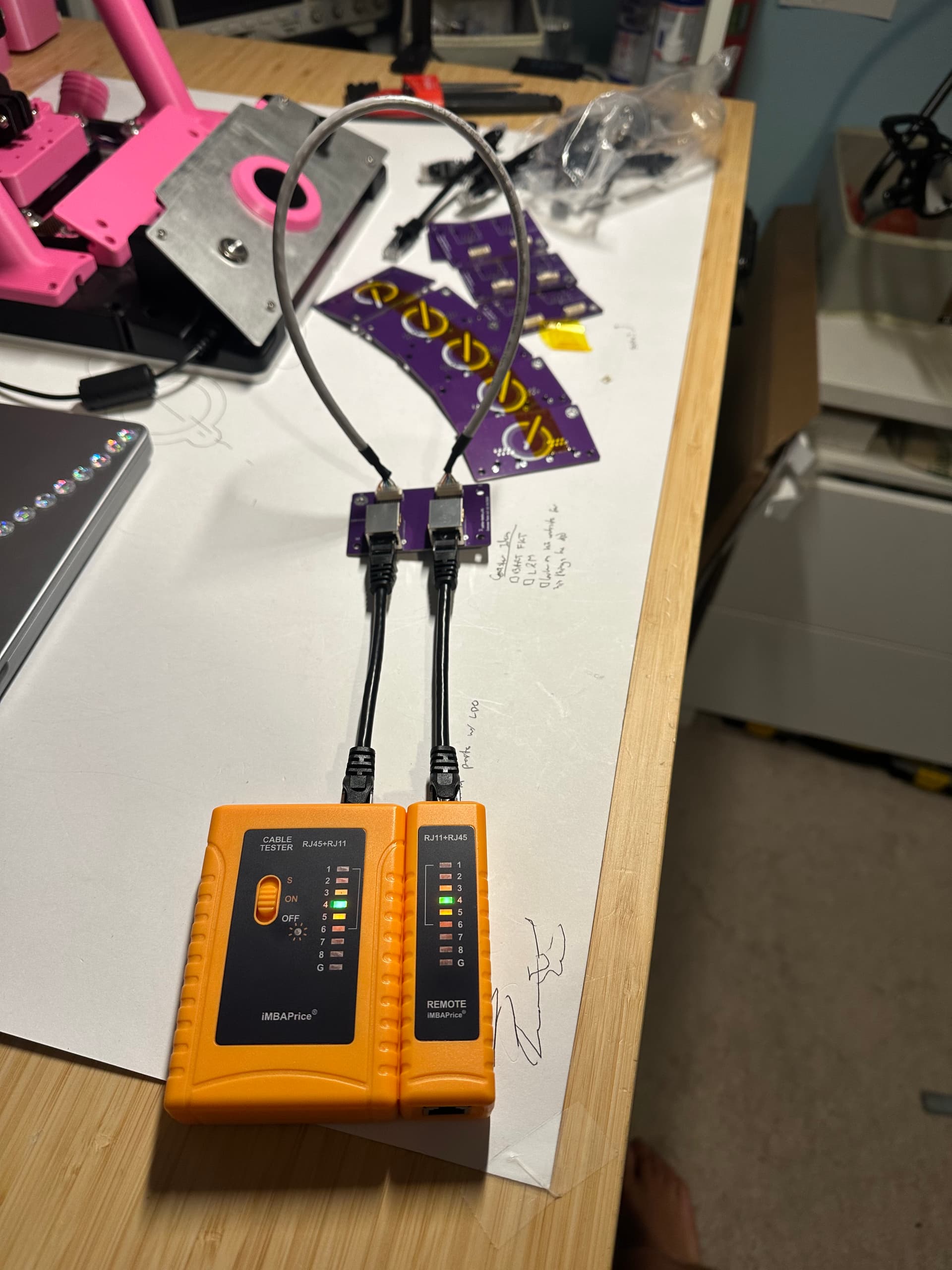
PCBs came in and it does the trick! At least for continuity checking. I just got the cheapest cable tester I could find on Amazon. Maybe it’d be worth it to get a nicer one that can test data transfer as well..?
2 Likes
I think that is not necessery.
You have no mega transfer rates on it.
And if you use CAT6 Patchcables ready assembled, they are proofed.
I got in our company a FLUKE DSX-8000
It will cost over 9.000 EUR.
I think that are ROCKETS on small BIRDS…
This tester is not testing anything other than continuity and lack of shorts, so it’s perfectly suited for this kind of test setup.
I don’t see any reason to try chase anything else, especially not data down the cable. Cross-talk should be fixed at design time, not tested for in this case. By the time it’s causing actual data corruption, your signal integrity is so bad that you’d already be running into real world issues.
1 Like
Heard, thank you guys! This setup should do just fine
Hi,
Finally dragged the PCB’s into KiCAD V9.0 they look fine. (Assuming I imported correctly ![]() ).
).
Might have reduced the number of ground vias but better too many than too few, otherwise looks good.
Sweet! Are they still easily editable after import?
Yes, just getting familiar with the new interface.
Couldn’t get the 3d model footprints to automatically import and had to manually re-assign them.
Can share the Kicad project files if you want.
Sure that’d be awesome! I want to start shifting everything to KiCad anywho. It’s such a better streamlined format, and exporting for manufacturing just makes so much more sense
1 Like
Compass.zip (5.5 MB)
Files attached.
See how you go.
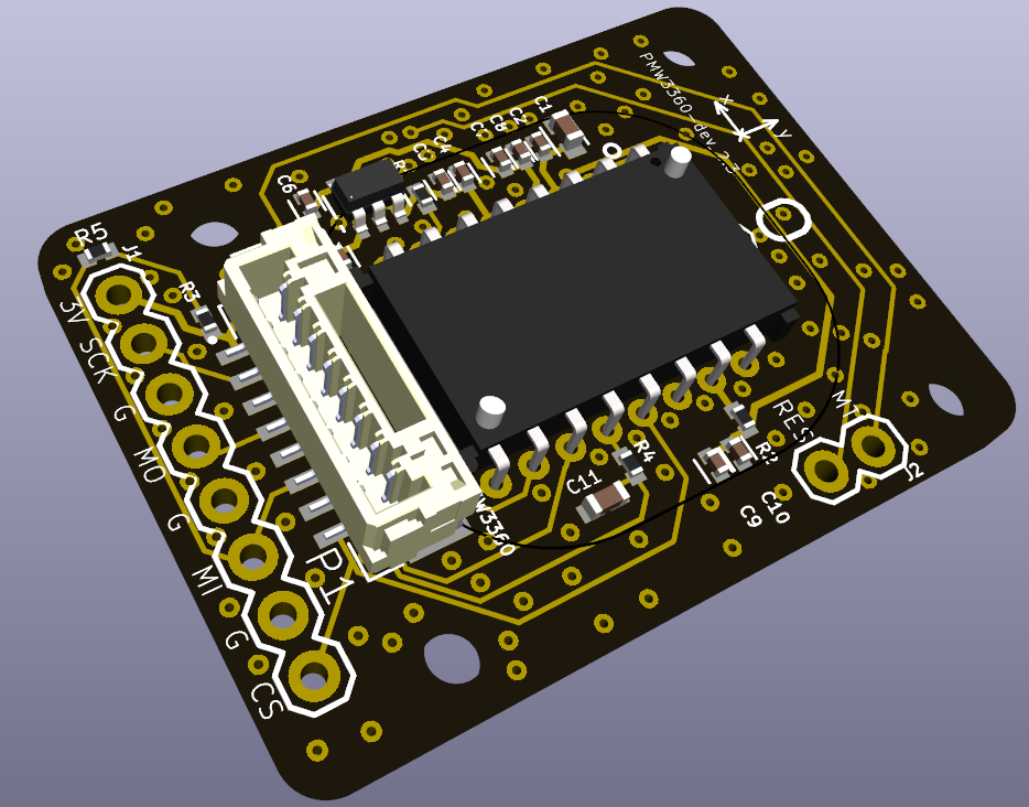
Not sure I should have brought the PMW3360 under the Compass project but haven’t had time to tidy it up yet.
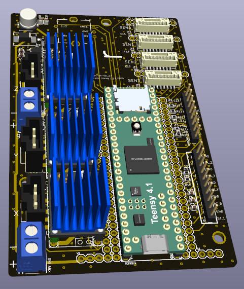
I haven’t uploaded the Teensy or TMC2209 3d models as these are large >18MB. You can download directly from Grabcad.
If it’s an issue I can share on Google Drive or similar.
1 Like