Absolutely, it’s always the ‘Hmmm, I wonder…’ type things that end up turning something up. Always good to double check all assumptions.
1 Like
So I went ahead and ran a couple experiments:
- First, to double check the control, I took out the tinfoil turned on the machine. Sure enough, the sensors didn’t initialize. None of them.
- Next, to debunk the magic tinfoil EMI hat theory, I replaced it with cardboard. And to my dismay, nada. A couple sensors initialized so it was a bit better than the control, but pretty sporadic
- Next, I again brought in the tinfoil, except now I wrapped it around the cardboard and stuck it back in the same position. Still not good, but better. Only one sensor that wasn’t initializing.
- Now, I thought I’d try to separate the cables manually and give them as much space as I could. This worked great. All sensor started up fine
- Now I wanted to test it against another control - my original build (Arnold) with soldered cables. They have the same PCB (actually the sensor PCBs are old b/c I didn’t want to waste good sensors, but I don’t think that matters too much), but the sensor cables are soldered. As expected, immaculate performance. I tried my best to get the sensors to fail, taping the stepper cables to the sensor cables and trying to get long parallel runs, but alas Arnold prevails. It’s funny because these cables are unshielded CAT5, whereas the fancy cables on the other unit (Clarence) are CAT8 and shielded.
- Then I went back to Clarence and now in the same setup he didn’t feel like cooperating. One sensor wasn’t initializing. So I swapped out the cable for one from the “bad” pile (while testing the cables for kits, a few of them refused to cooperate - even without stepper motors connected) and sure enough still no good. Then I swapped it out for one from the “good” pile, and voila - everything working again. Nothing even had to be separated.

Not really sure what to make of this. I don’t know if it’s quite enough evidence to say for sure that the connectors are the issue. I’d like to dig deeper with a probe, but I got other pressing things on the todo list right now. I will also try adding caps when I have a second.
1 Like
Interesting. It would be fascinating the follow the thread of the cables being a factor. As a first thought I’d be concerned that it was an intermittent issue that just happened to line up with a cable replacement so I’d be going back and forth a few times until I trusted that it was definitely the cable and not random. It could very well be a poor crimp somewhere and the working/failing could line up with other things like having manipulated the cable lead to strain on the joints, pressing conductors into the crimps etc. That’s kinda the thing with crimped connections, if they’re correct they’re bombproof but if they’re not, they’re horrible.
It could also be that by adding the series resistors you’ve made the system less noise immune. That’s definitely a risk. Without the resistors there the drive impedance is lower so any induced noise currents will result in less voltage. With just the resistors the impedance of that line is higher and the noise currents result in larger voltages. Adding the capacitors in then reduces that impedance again accordingly. The increased impedance of the resistors will limit the amount of noise produced by the switching of the SPI lines so they’re still definitely worth having, but there could be other side effects.
The other thing is that I’d very strongly encourage people not to assume that a shielded cable or higher CAT rated cable is any better, noise-wise, than not. It may well be that the shield is acting as a big antenna and causing there to be much higher noise currents in the system. That’s no problem if the shield is properly terminated to an enclosure or ground plane on either end, but if it’s not then it’s conceivable that it’d make things worse. Also, I remember the last EMC training course I did specifically called out the shielded modular comms connectors for ethernet as being examples of incredibly poor shield performance in a number of ways.
1 Like
Yeahh I could honestly see them being bad crimps. When I was working with the manufacturer, they were saying how crimping the ethernet cable was giving them a bit of trouble. The conductor gauge is on the large side of the JST GH connector’s limit, so it was especially hard trying to cram in extra shielding conductor. Wish I had just gone with lower CAT rating and no shielding ![]() hahah live and you learn
hahah live and you learn
Ok that is actually super interesting. I wish I had some CAT5 crimped cables to test out. I guess I could just snip the shielded connection…?
What are the shields connected to?
The cable shield is connected to one of the ground pins on the cable.
You could and see if it changes anything, but it may not because the cables internally have a huge amount of capacitance to the shield conductors, so it may change things but not super predictably.
Is the shield connected at both ends? Do both boards have a good ground plane?
They’re only connected on one end. To the best of my knowledge, both boards have good ground planes. They’re the same designs that you kindly helped me work through. One thing to note is that I haven’t really taken care to make sure that all the sensor cables’ shields are connected on the same end - i.e. all grounded on the motherboard or all grounded on their sensor boards. Looking at it now, they’re definitely not consistent. I’m not sure if that would matter much? I fiddled around with that bit while testing them initially but got unpredictable results.
Shields should pretty much always be connected at both ends. If they’ve got good ground planes on both sides then you should be able to get a decently low impedance connection from ground to the shield. It’ll always be compromised at higher frequencies due to the tail that’s going into the pin connector and the impedance that that adds.
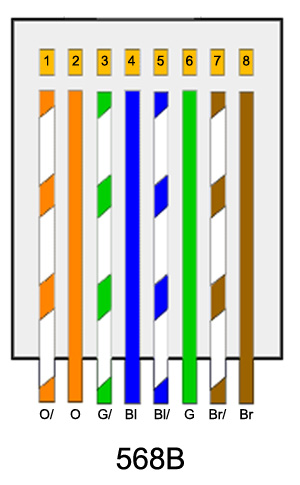
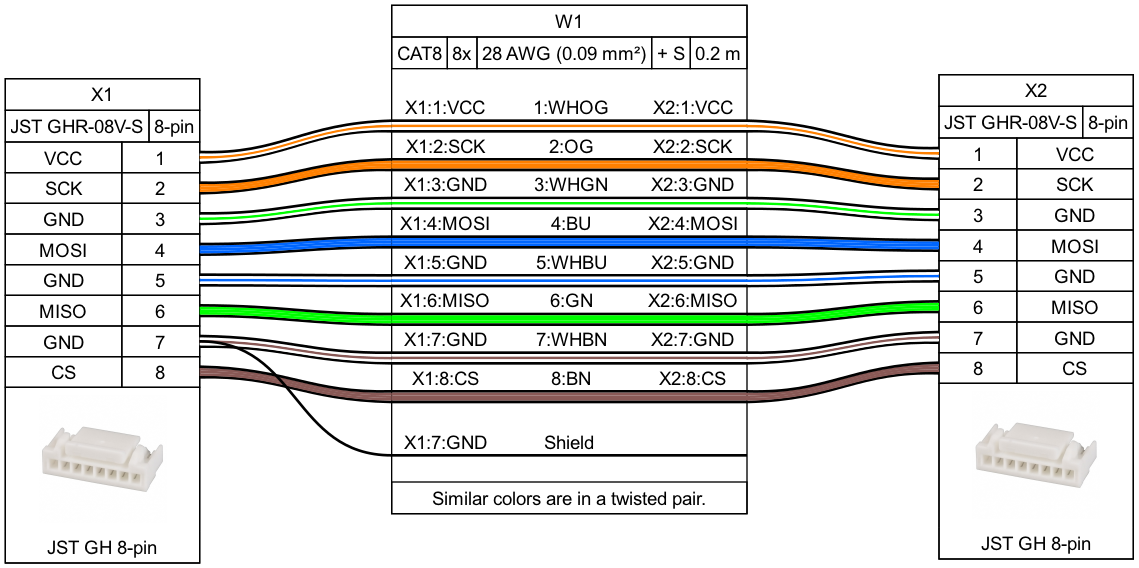
Thinking about it, you’re using 4 twisted pairs for this. Are the pairs/colours used the same in every cable for every pin? What does that work out to in terms of which signals are on which pairs?
Oh ok, for some reason I thought they should be connected on only one side. I think my initial impression was connecting on both sides would create a ground loop. But I guess that is mitigated if you have good ground planes?
Yes.
This is the current config:
Yeah, you’re not alone in thinking this, I think I thought the same for a long time. Hell, there are a LOT of resources out there, even ones from big names in the industry that claim this.
They do create a loop, but that loop has no area if you use good termination practices so doesn’t have an EMC penalty, or rather it does but that penalty is vastly outweighed by the benefits of having it connected to the reference plane at both ends. I really need to get out of the habit of using ‘ground’ to refer to the return/reference conductors/planes.
It creates a parallel DC path so current will flow in the braid/screen, so care is needed there but in most cases that current is DC or such low frequency that it doesn’t have EMC ramifications either and low enough that this isn’t an issue. If there’s the potential for extremely high DC currents then the shield can be AC coupled (which is a bit ugly), the power supply can be isolated or the far end supply can be isolated, all of which can eliminate that issue. Or it can be mitigated by running a bigger return conductor with lower DC resistance.
That pinout looks all good, I think we had discussed that before.
1 Like
Also, I did some more experiments. TLDR: still not really sure I have figured out anything conclusive…
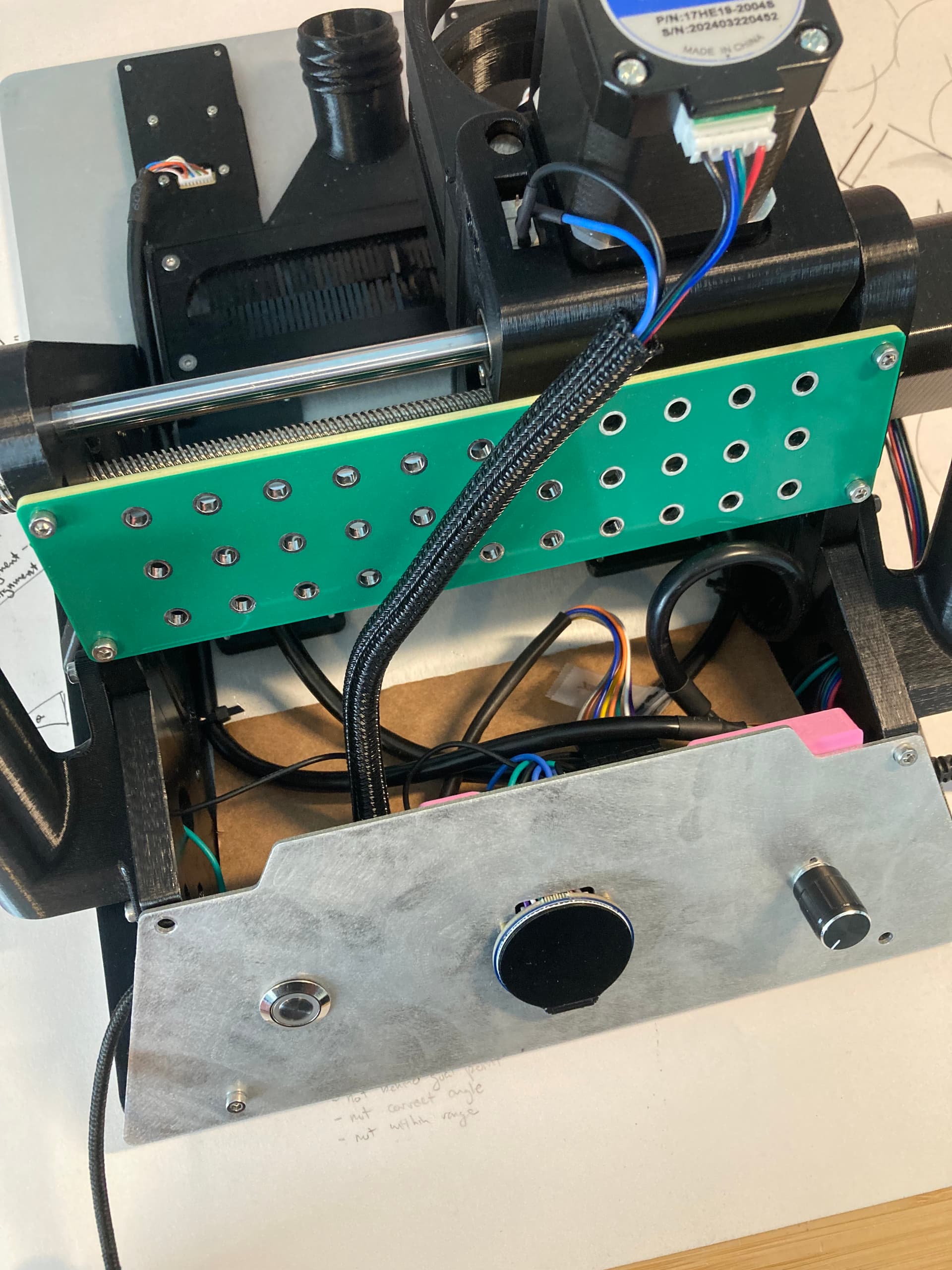
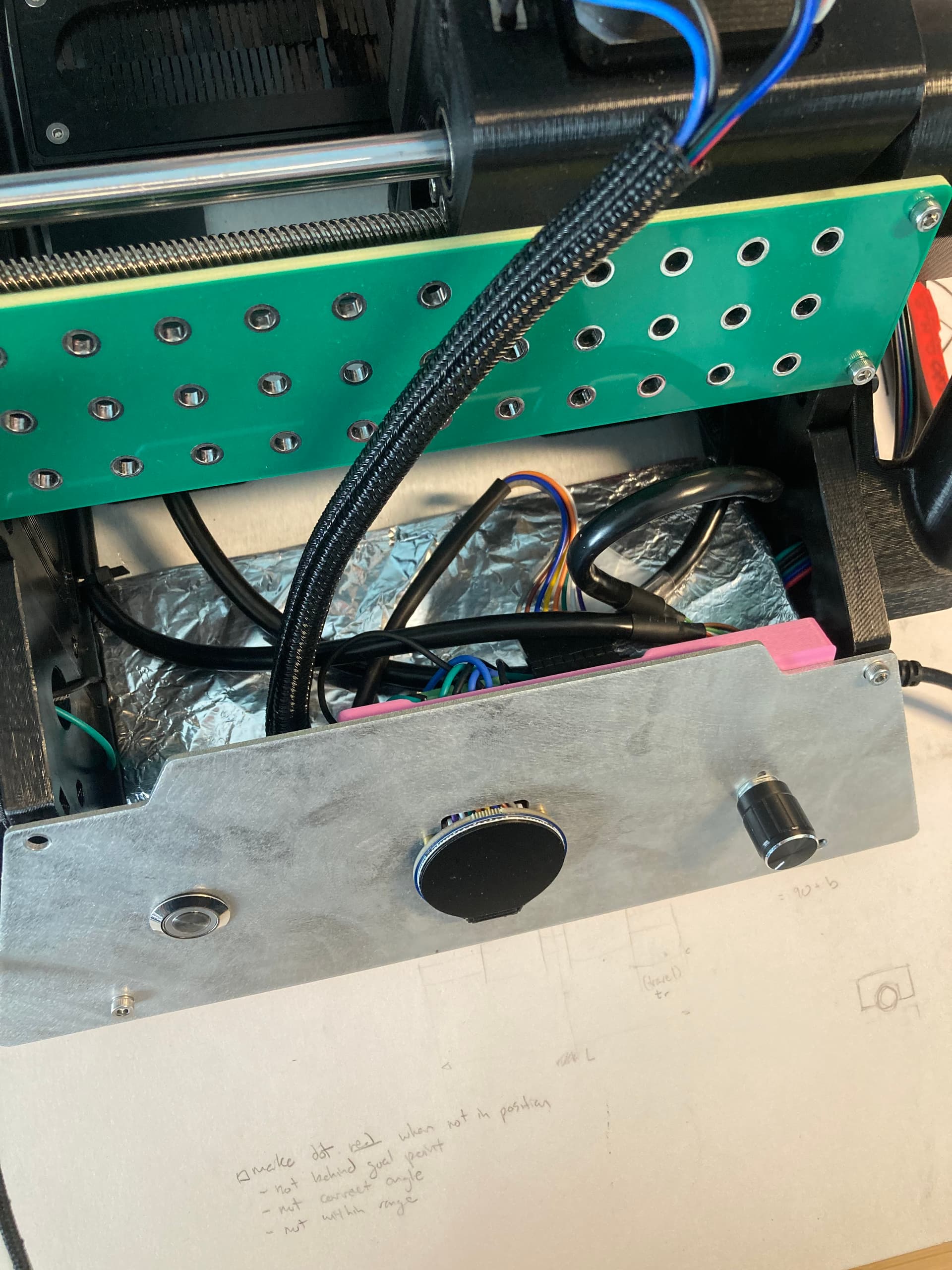
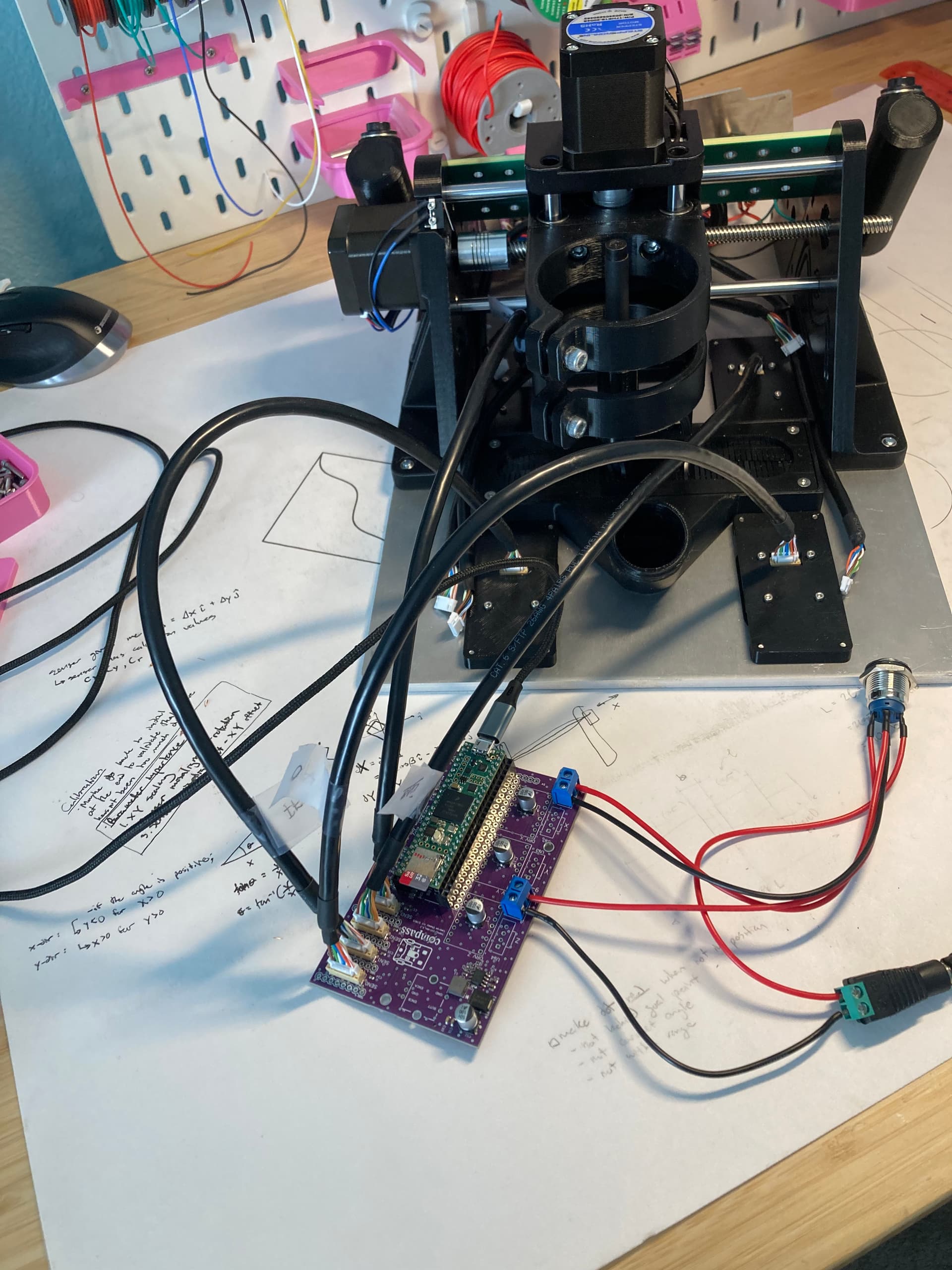
I soldered another board so that I can test everything more easily. There are no more stepper motor cables here, so those can’t be taken into account anymore.
- Starting an initial test with the board, using 4x 40cm “bad” cables to reproduce bad sensor initialization. And what do you know, I can’t reproduce it - all sensors started up fine even with the “shitty” cables. Tried it for a few power cycles and still good.
This is theoretically the same setup as when I was initially testing the cables, but with a couple caveats: different PCB (so different soldering), using 4x 40cm cables instead of 2x 20cm and 2x 40cm, using a different barrel jack adapter for 24V (actually realized that the adapter I had been using before has a super loose connection), potentially different wire routing and layout, no consistency on cable orientation. Could it be that the sensor headers on Clarence’s mother board are slightly worn out from the plug-in/unplug cycles of testing all the cables?
- Swapped out the barrel jack adapter. Still good results, even with power cycles and wiggling it around inappropriately.
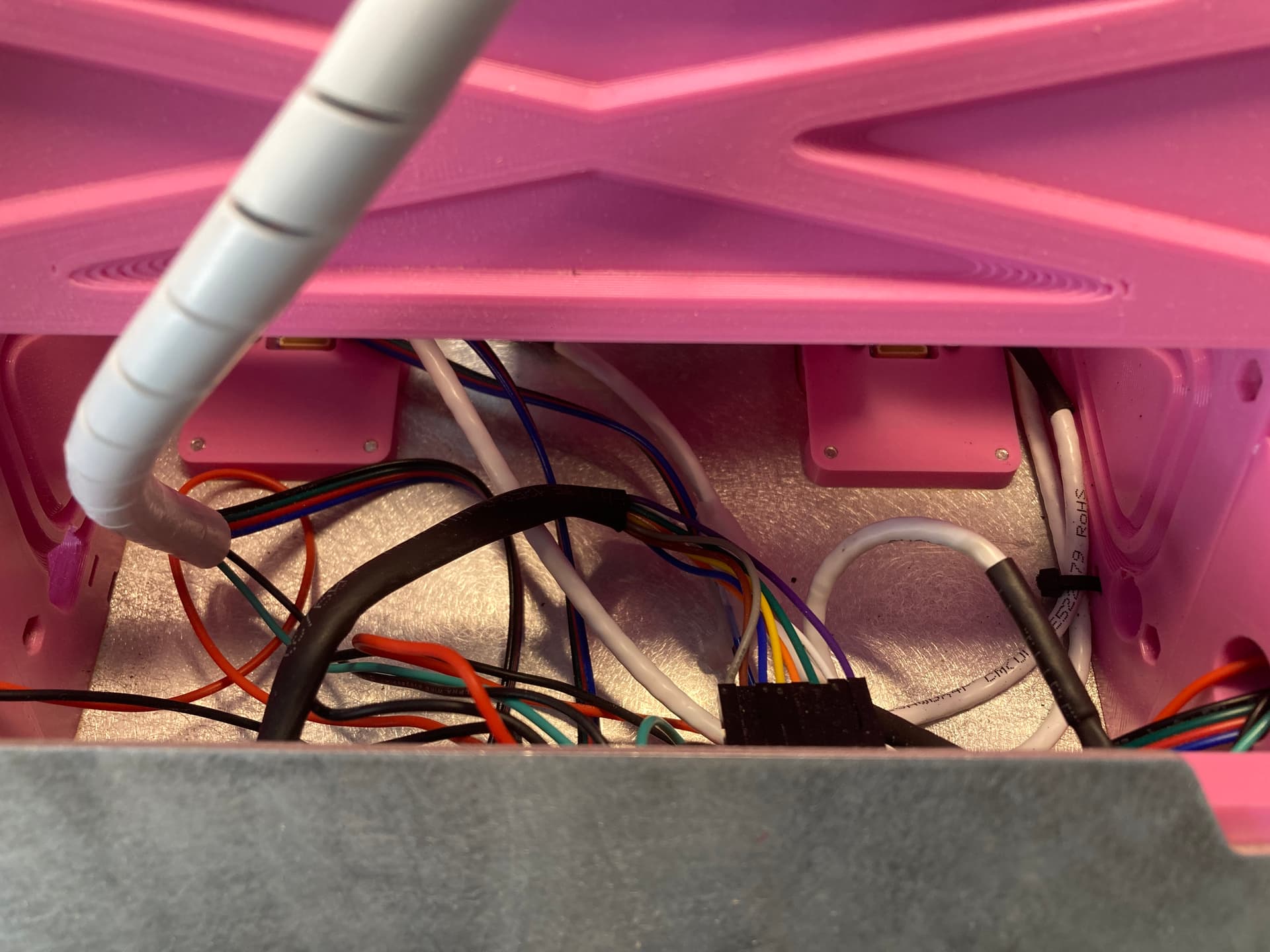
- Took the motherboard and all the peripherals (everything except the rotary encoder) off of Clarence and tested with the same cables. Alas, nothing. None of the sensors initialized. I tried removing the motherboard from the UI panel to try to make the setups even more similar. A bit better - 3/4 sensors, inconsistently - but still unpredictable and not 4/4.
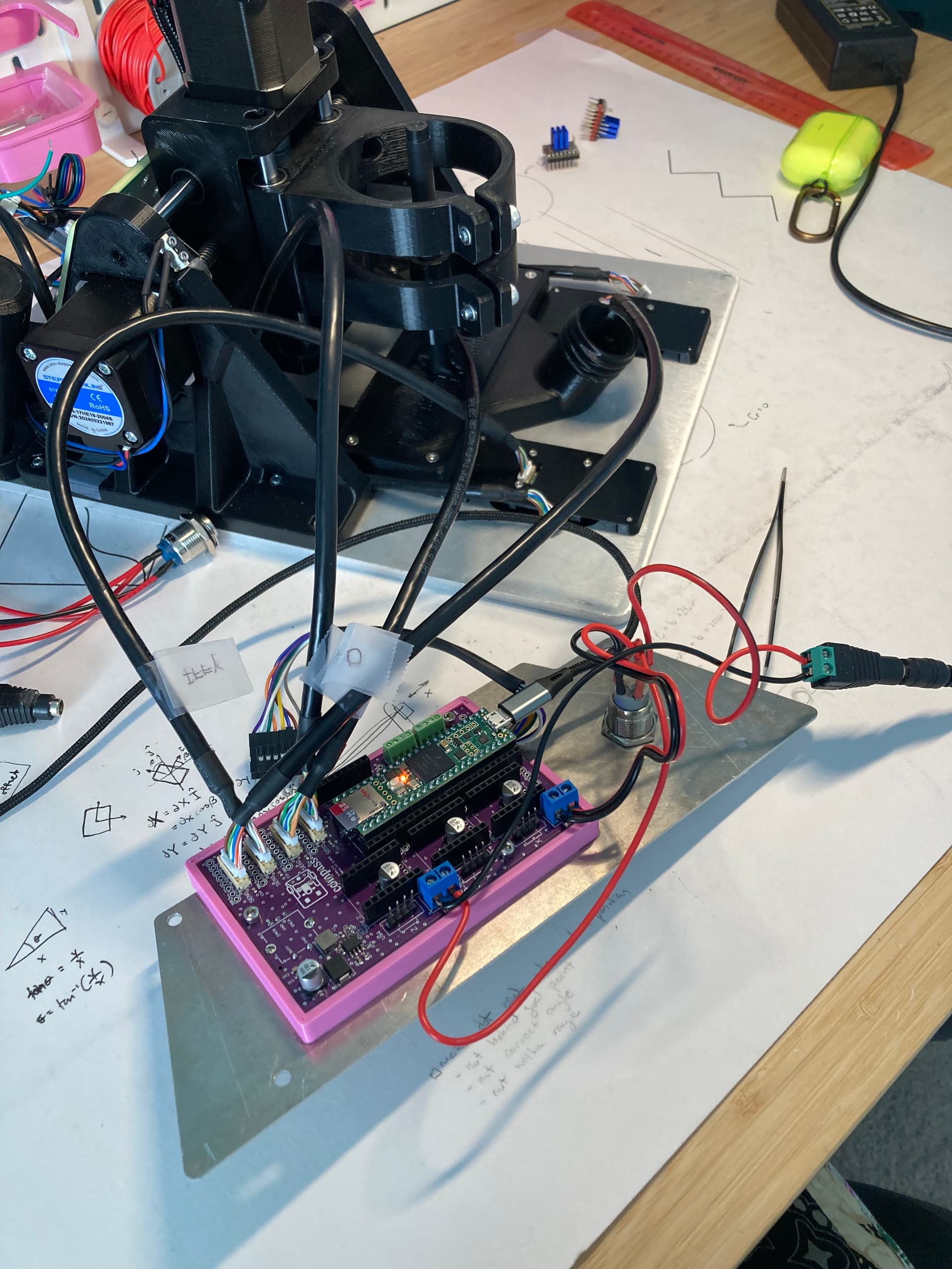
- Now I switched back to the debug board and plugged in everything the same way. Now again only 3/4 of the sensors initializing. I was able to get all four sensors to initialize by fiddling around with the cables and putting them in different positions. It’s hard to tell whether this worked by moving the cables away from each other (or away from the USB cable), or if it worked because I was putting the connector at a different angle in the header.
A tricky little bugger this situation is. I am messing around with some capacitors on the SPI pins now…
1 Like
Ok that’s super interesting. Just from what you were telling me before about unintentionally making whip antennas in PCB design, it does make sense that only connecting the shield on one end could have that same effect.
What actually are the benefits of this? Does it have to do with minimizing that “antenna” effect, or just minimizing impedance…or something else?
The simple answer is exactly that whip antenna case. If you take a long wire and connect one end you’ve got a whip antenna. Make that a shield conductor and then you’re routing your signals through that antenna. There’s a huge amount of capacitance between all the wires in that bundle and the shield so any voltage on that inside surface of that shield couples well into the conductors. Each of those conductors will have differing impedances so the resulting voltage at the far end will differ, leading to induced noise.
The best option is to terminate the shield to a metal enclosure at the other end using a good high-frequency connection around the entire thing, like through an EMC gland. Then it doesn’t matter what the conductor is doing because all of those currents flow on the outside of the shield and don’t couple to your signal conductors.
The second best option is to terminate the shield to the reference plane at the far end because at least then the currents are being conducted into that far end reference plane and the signals will have less noise on them because both the signals and reference plane will be ‘moving together’, in a voltage sense.
A while back I attended an EMC course with Keith Armstrong who is one of the biggest names in the EMC industry. He had a couple of slides that very elegantly illustrated the situation. I’m sure it’d be fine to snip a chunk of diagram to help explain.
2 Likes
Gotcha. Thanks for the explanation, that’s super interesting
Hey @jono035 , I’m curious if you have any advice for testing the cables after manufacturing? It’d be great for the sensor cable manufacturer to be able to test the cables before sending them to me. Normally I just plug the cables into the main PCB and into the sensor PCBs and power cycle the unit a few times to make sure the sensors are connecting reliably. But this requires a main PCB, 4x sensor PCBs (and 4x sensors), a display, and a Teensy, which is kind of expensive. It’s also probably not the most comprehensive approach. I would also have to send this whole testing unit to China for them to use it.
Are there better ways to go about this?
1 Like
I’ve never worked with testing cable looms before so I don’t have any direct experience there, unfortunately. There are a couple of ways I can think of that would match up with how I get stuff tested now. I would also ask the supplier for any suggestions based on what you’re concerned about.
What specifically are you trying to avoid? That’s what informs the testing you’d need completed.
If you’re just worried about connections being correct, you could ask them the test 1:1 for continuity with a multimeter. This could also be a manual inspection, holding the 2 ends of the connector together and verifying colour match or similar, assuming it’s a colour coded multi-core cable. It may sound silly, but it’s generally good to assume the cheapest case option will be taken, so assembly without even visual inspection unless specified. Specifying that all cables need to be visually inspected as a separate step after assembly means they’ll hopefully assign some time to it.
If you want to just test continuity you could throw together a simple PCB or test harness that loops a 5V connection through the entire thing and lights up an LED if it’s all good.
If you want to test both you could build a board to do it or build that function into the main board. I would just loop the pins to and from some GPIO and then just raise/lower each on in time, lighting an LED at the end if it’s a pass.
If you need any more than that, like crosstalk measurement, that’s gonna start to get into specifying what particular test equipment they’ll need to have on hand and how they should hook it up. If you were wanting reliably multi-GHz signals on custom cable then maybe I’d consider that, but at anything below I don’t think I’d bother.
That’ll all also come down to how many you’re having made. If it’s 100 cables I’d potentially just do it myself as they arrived to double-check. If it’s 1000 cables I’d ask them to do it manually (multimeter, 6 connections, maybe 10 seconds per cable? 360 cables per hour, 3 hours to test a batch of 1k, probably cost you US$50-100 depending on a bunch of stuff, China isn’t as cheap now as it was even 10 years ago). Any more than that and I’d be thinking about how to speed it up. Custom board with the connectors being plugged in one at a time still won’t be super fast, but probably 2-3x faster than manually checking it, etc.
Any time I’ve gone this route, I’ve added in resistors at each loop so that you can detect whether there’s a short in a connector (or elsewhere). Of course you need a little more than an LED at the end, then.
If you want to test 8 or fewer conductors in a cable assembly, a pigtail to an ethernet cable tester is sometimes good enough… tests for shorts, crosswires, etc.
2 Likes
I was assuming that shorts within a cable assembly would be relatively unlikely and easily spotted with a visual inspection, but that’s more gut feel than based on any experience.
The ethernet cable tester is a great idea. You could make a small adapter board that breaks 2x ethernet sockets into the appropriate cable connections and then bypasses any unused pins from the ethernet connectors. That way you’d get the expected ‘all good’ result with a correct cable.
1 Like