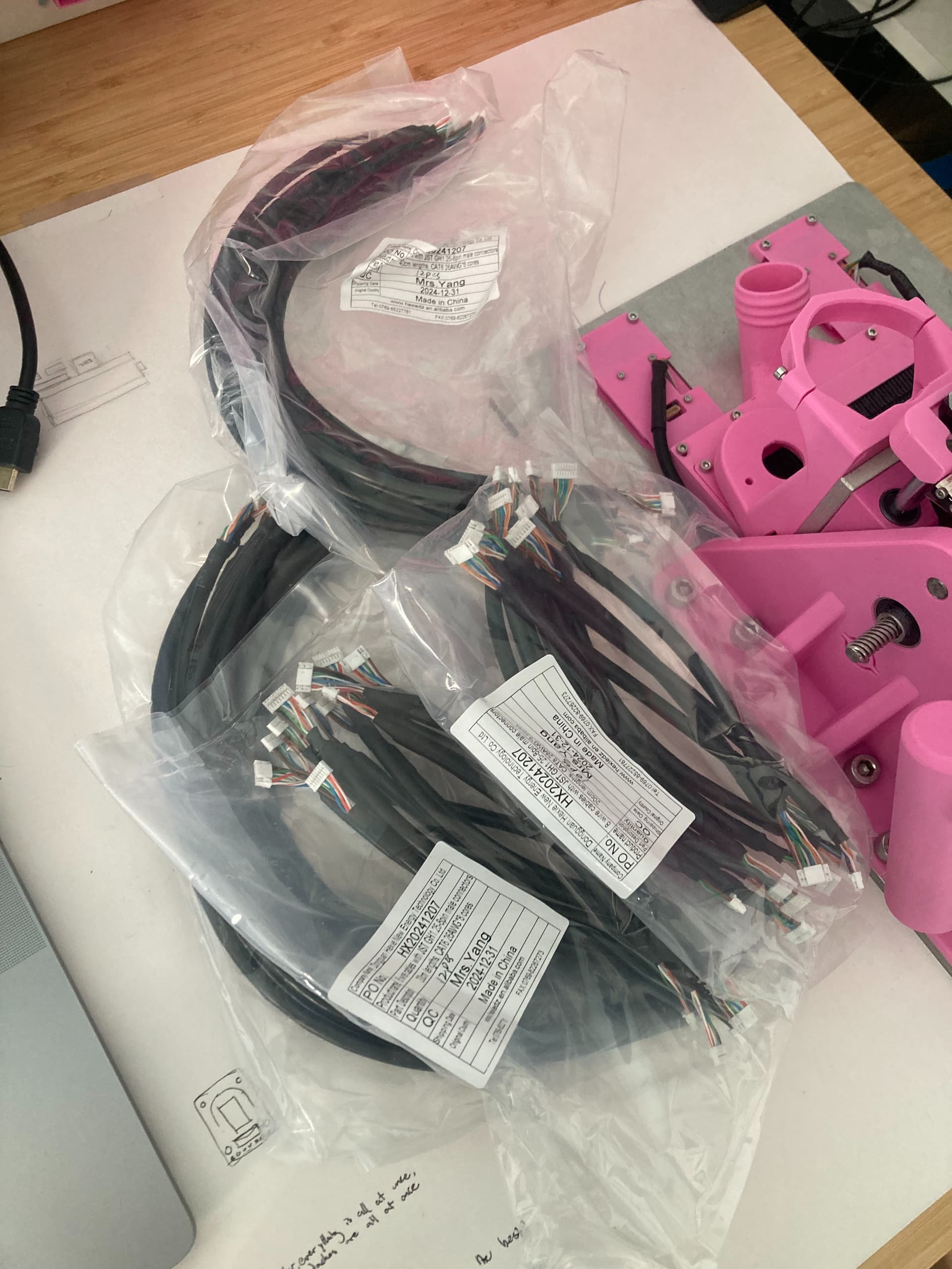
New cable samples with JST GH connectors just came in from China. Super excited to try them out but I gotta wait for the new PCBs to come in too… Oh the woes of international shipping.
Yeah totally. It sucks. Trust me. I started off trying to crimp them all on my own a couple months ago and it took forever. Finally finished them and it turned out my sensors wouldn’t initialize with my janky hand crimps. Ended up just soldering the wires in. Not a terrible option, but it was crushing to have that whole crimping process be in vain hahah. There were a solid couple of days where I was convinced the issue was static from my new carpeted floors too… Had me going crazy.
I hand crimped 100-200 MPCNC’s worth of wires in the early days while looking for a good source. Those are much bigger crimps though. Rarely will I ever touch a hand crimper these days, I put in my time for sure.
Also super stoked to see that the cables work amazingly. The GH connectors are pretty awesome. Such a nice, satisfying “click”. All the sensors initialize and work super smoothly. I did order shielded cabling before you advised me of its unwarranted advantages @jono035 , so I’m still curious to see how a low rated CAT cable would do. Will probably try that with soldered connections for my other device.
Just found out about this group and joined. Awesome project. I’m an electrical engineer and love to fab on CNCs, among them Shaper Origin. If I can support the cause - debugging, alpha testing, etc, - give me a shout.
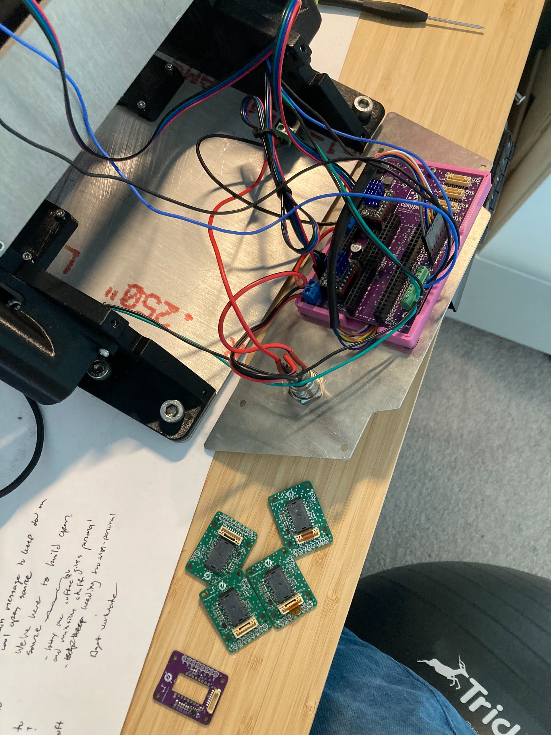
Little update, would love to get opinions on this: the JST cables were working great for a bit, but now the sensors are having trouble initializing again. I think there might be some slightly imperfect connection that makes the system more sensitive to noise…? I have had absolutely zero problems with the soldered cables on my other unit.
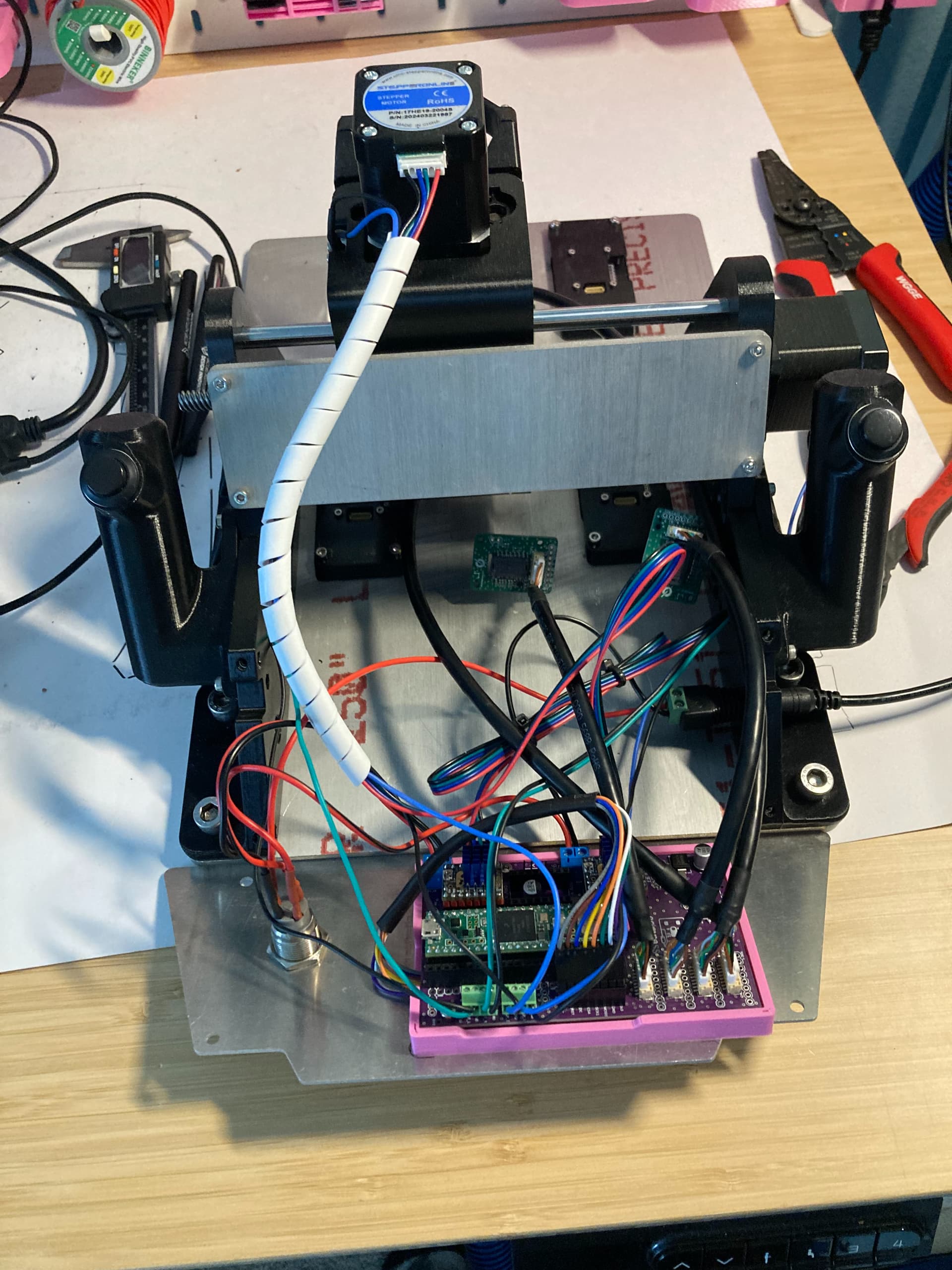
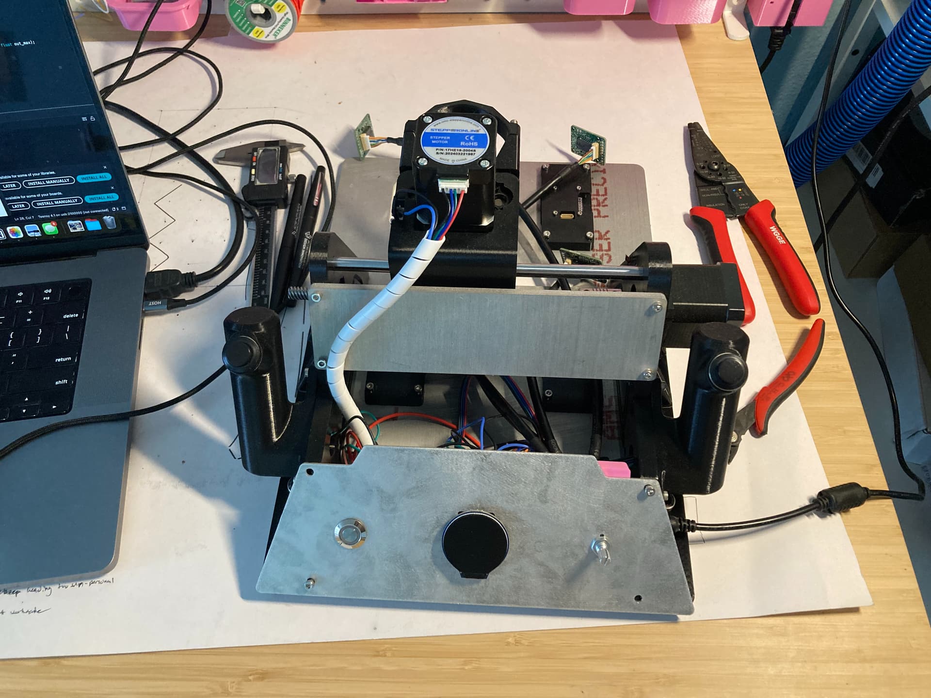
Doing a little troubleshooting and the connections are definitely finicky. I fiddled around a bit with the cables and found that the sensors have no problem initializing when the stepper motors aren’t plugged in. That makes me think there’s some sort of noise coming from the stepper cables that gets transferred onto the sensor cables.
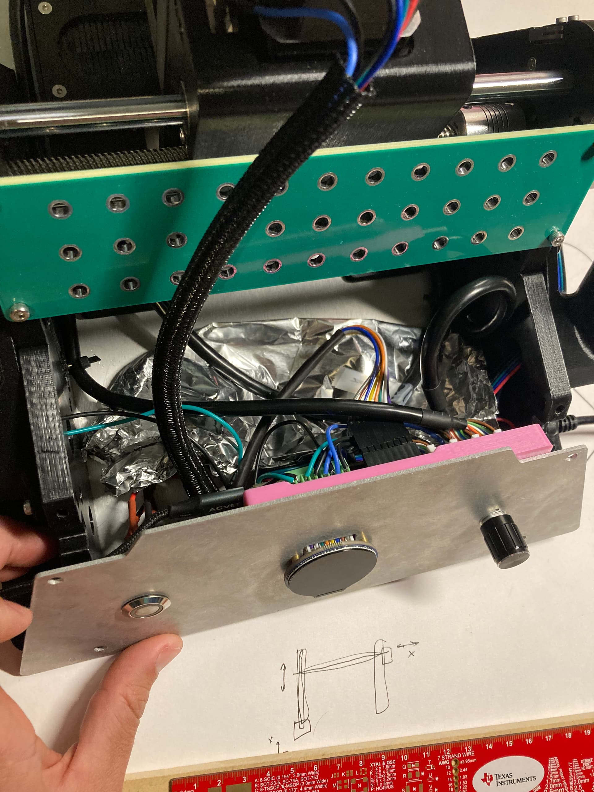
I folded up a bit of tinfoil and wedged it in between everything so that the sensor cables are separated from the stepper cables. Surprisingly this works lol.
I definitely want to find a longer term solution for this hahah (more robust too - I accidentally shorted a couple pins on the Teensy already ). All my SPI lines have a 100R series resistor and a DNI capacitor to ground. Would throwing in some caps make the system more resilient to noise?
Yeah, tons. Throw a scope on your signal wires and you’ll see lots of induced noise. I would shield either the stepper wire bundles or everything else.
It may well just be different wire routing and different layout. I wouldn’t expect the connectors to have any effect.
If it were an issue that was coming and going when there were vibrations or bumps/knocks then connectors maybe.
It could well be that. The chopper drivers in the stepper motors are very rapidly switching the stepper connections from +24V to GND and back so there are very fast voltage changes that can capacitively couple into nearby cables. The current in the stepper coils will also have a slight triangle wave look to them which will create a magnetic field around the cables but nowhere near as much.
And that right there is the exact problem with EMC/EMI issues. You can fix a lot of things by just changing stuff. The real work is in backing out those changes and testing things to verify exactly ‘why’ a fix worked and how best to replicate it in reality. It may be that the tinfoil is acting as a capacitive ‘grid’ connection and screening the cables from the steppers. It may be that it has just pushed them further apart.
I would try to bundle all the stepper motor cables together and route them away from any of the communications cables.
I definitely wouldn’t go through the hassle of shielding/grounding anything. That’s generally best left as a process of last resort or for extremely long cable runs because it’s extremely difficult to do well and may even make the problem worse unless you have shielded/screened enclosures at either end.
Yeah, that’s exactly the one. If you figure out the frequencies that you’re dealing with in the comms then you can size the capacitors accordingly. If you’re using a 100kHz data rate then you realistically want around 1MHz of bandwidth to make sure that the square edges stay square-ish. 100R and 1nF is a 1.6MHz corner frequency so anything at 1.6MHz will be reduced by 3dB and anything beyond that will reduce at 20dB/decade. Fundamentally though it’s a kind of ‘play with it and see’. I would try 1nF capacitors at both ends and see what that does. If the comms works with steppers enabled and disabled then that’s great. If the comms doesn’t work at all then the filtering may be too much and I’d fit smaller capacitors, maybe 470pF at both ends. If the comms works with the steppers disabled but fails with them enabled still then I’d up the caps by adding a 2nd one on there. Adding a cap at the receive end of the signal works best because that’s what’s receiving and reacting to the noise. Adding a cap at the transmit end is more for reducing the noise that the transmitted signal induces on the adjacent signals but will also help a bit with reducing noise.
Another thing that you can do is, as Daryl suggests, stick a scope probe on the pins and see if you can see the noise. If you can, that’s great because you can reduce it. Sometimes just adding the 10pF of probe capacitance can fix noise problems which is frustrating but also shows that adding capacitance helps.
Personally, I wouldn’t be trying to do that at this stage, especially not for something that’s being developed as a product. You really don’t get ‘that’ much rejection from shielding without following that up with careful routing of ground paths and enclosure design to direct the noise currents to the right places and I don’t think it’s worth it for the cost/complexity increase, especially considering how bad small scale connectors are at handling shields.
Ok sweet! I will experiment with capacitors and a probe then. Are there specific SPI lines that are most important to reduce noise on? I think I remember you mentioning before that the CS lines aren’t quiet as important? Would be nice to not have to add caps to everywhere when doing trial and error testing. I guess another approach would be to just start with one line and tune it with the scope.
I’d start by having a probe around. That way you can also try with the cable routing, poking tinfoil in places, try with the steppers moving or not, etc. Step 1 is always to try to understand the cause of the problem with as much specificity as possible!
If there’s enough noise to cause corruption then all the pins will be equally important and a state change on any of them will bone you. The CS line is easier to deal with because it’s slow so you can put a MUCH larger cap on it, like 10nF straight off the bat, while the other pins you need to delicately balance too little filtering to help vs too much filtering and destroying the signals you’re using.
Edit: Also, bear in mind that the capacitors don’t ‘fix’ the signal, they just redirect the induced current to the return path which lowers the voltage seen. They’re a good idea, but they’re still a band-aid for solving the problem by not having that noise induced in the cables in the first place, which would be a wire routing change if I were to guess.
Heard. I’ll mess around with it. I am about 80% sure it’s the stepper cables that are causing the problem, so proper routing is a good call too. I’m now remembering that I had to add decoupling capacitors to the endstops a while ago because they were getting triggered by stepper pulses.
Anywho I should be able to direct the wiring a lot better with a better enclosure for the board. Might also replace the tin foil with paper or something non-conductive as a fun little sanity check.