Hi All - I am new to the 3D printer universe. I have many years experience in the CNC universe. I build small CNC routers and lasers usually use UCCNC and individual BOBs controllers and drivers… I have come to the conclusion that boards like BTT are far superior to the ones used in the CNC world so want to use and learn about them. Particularly for input shaping. I’ve come here because the BTT boards are used for 3D Printing and CNC which is attractive. I want to use say a BTT octopus or SKR for a chocolate printer and then a CNC MIll I want to make. I thought I’d start with the printer to gain some knowledge. So is there a cookbook on where to start the BTT journey? Is the documentation that comes with the boards good enough for a total newbie to get a machine going? Is Clipper better than Marlin? Clipper has the input shaping with BTT… So where does a beginner begin? Thanks Peter
There is good documentation available on GitHub for big tree tech boards. Marlin firmware is open source and V1 Engineering provides pre-compiled firmware for use with certain big tree tech boards for Mostly Printed CNC work (Primo and LowRider) and also for 3-D printing in that Ryan has a CoreXY 3-D printer that he designed and built and is helping others to build.
Editing of Marlin firmware and compiling of it is usually done by use of Microsoft visual code studio, which has a free version available. There are a couple of plug-ins that help with that, such as the Build Marlin plug-in and another one I can’t remember right now.
I can’t remember if input shaping is being done with Marlin or not, but I suspect by now, it’s perhaps doable, though mostly I have heard about input shaping with regard to Klipper. I’ve purchased supplies for building some CoreXY printers, and I planned on using Klipper instead of Marlin for them, even though all of my 3-D printing up to now has been with Marlin, and all of my CNC work up to now has been with Marlin, with the only exception being my LowRider 3 based plasma cutting rig, which uses LinuxCNC as its control software. I’ve purchased an input shaper device and these planned new printers are the reason for me buying it.
The manuals for the boards are ok. They have the info in them. But I don’t think they are that beginner friendly.
Marlin does do input shaping. I can see the benefit on a high performance 3d printer. But not for a CNC.
Teaching Tech on youtube has a lot of good videos related to the questions you’re asking. He was a teacher when he started. So he is very good at describing things for beginners.
Our firmware for BTT boards is at MarlinBuilder releases. The instructions for installing vscode and building it are at platformio. I don’t think the build marlin plugin works well with our firmware. But I have never tried it.
I have been using Klipper on my printer and it has its benefits. But it is not perfect. Feel free to try it Doug, but if you know Marlin, you will find Klipper to be a bit of a pain. It needs a lot more command line, and a lot of features aren’t well documented. Honestly, the core Klipper project is great, but the connecting bits of moonraker, mainsail, fluidd, are not as mature. It does work well once you figure it out.
Hi Jeff - CNC routers and mills have the same vibration issues as printers and input shaping solves most of those things. Traditional hobby CNC motion controllers are way behind the printer controllers using shaping. Most of the math for shapers was figured out about 30 years ago for CNC machines, way before 3D printers existed. Peter
If you’re willing to discuss this. i am interested in understanding that point of view. I am always interested in improvements. I don’t want you to feel defensive about it though. We can agree to disagree if you like.
But here is my thoughts on it:
- The vibrations I see in my final work are due to vibrations from two sources. 1) The bit frequency matches something in the machine and resonates. That chatter moves the bit around. Input shaping doesn’t control the speed of the router, and the gantry doesn’t even have to move to see this error. 2) As the bit moves linearly, it can have oscillations perpendicular to the motion. This shows up as waves on the surface. This is due to the forces of the bit as it gets pushed away from the work, not ringing from the inertia of the gantry. This is similar to the washboard pattern on dirt roads. Once the pattern is there, it amplifies itself. The frequency of the pattern is based on the linear speed and the load from the bit.
- Pure fast motion is only done when traveling. Ringing when traveling is not going to bother me.
- In the case of a fast laser engraving (100mm/s+), the vibrations would be able to be reduced by input shaping. 3D printers are moving commonly moving over 400mm/s not on the high end machines where you would see this kind of feature. The benefit of inout shaping are much greater at greater speeds. Maybe it would be useful at <25mm/s. But my brain just doesn’t think the forces from the input shaping are close to the milling forces at those speeds.
- I have no doubt they were doing this on industrial cnc machines 30 years ago. But I also know my MPCNC has a lot of differences to these giant steel machines.
Maybe your machines are faster than mine. Or maybe you are doing super high speed 3D carves like Steve Potter.
I am totally in support of you trying it though. I am not trying to be a wet blanket. I want to understand more about where my thoughts are wrong…
Hi Jeff- Totally happy to discuss machine harmonics. Open to all chat - got to learn somehow.
The “bit frequency” vibration is called the runout frequency. The tooth chatter is called the tooth passing freq. Plus their harmonics. See attached article, sorry can’t include links ![]() so I’ve snipped their headers for you to search.
so I’ve snipped their headers for you to search.

. These harmonic inputs can’t be removed but what happens is they get amplified by the machines structural compliance. Particularly if some part of the machine has a similar natural freq to any of the harmonics. Then we move onto machine damping.
The structural compliance is what the input shaping minimises. There is no substitute for machine rigidity though and this is the machine designers mantra. When it comes to fast motion you are dealing with jerk and jounce. This is the rate of change of acceleration. Jerk has no physical consequence. Accelerations create inertial forces, a physical consequence. Jerk creates very unsteady accelerations which create unsteady inertial body forces which affect the printer head or the spindle by wobbling it. This affects the print or the cut.
if you differentiate distance with time you get velocity, then acceleration, then jerk, then snap, then crackle then pop… ![]()
Traditionally mills are made of cast iron which is damp, but not damp enough so in servo systems there is a feedback loop that monitors accels and does the same sort of thing that shaping does. It modifies the velocity curves or the actual path (path smoothing) (using a PID system) to minimise jerk. I use jerk here in the engineering sense not the lay sense. Lay persons jerk is unsteady or rough motion which is a velocity thing not necessarily about accels.
Traditional path planners use a trapezoidal velocity planning. At the knee of the curve it is an instantaneous change in velocity which is an infinite accel ie very high inertial forces are created. Then comes s-curve planning which adds a small curve to the knee to smooth that a bit. But this is an arbitrary strategy. Input shaping identifies the machines natural freqs and addresses these directly in an open loop manner. In time with accelerometers now permanently on machine heads closed loop shaping will be used to make motion even smoother just like high end mills do with their servo systems…
So hope this is helpful to start the understanding…
In my case I build medium to small routers and customers ask for more and more speed. With the advent of high speed machining strategies harmonics have become a big thing. I have concluded that printer tech is moving much faster than CNC tech so have jumped across to this Universe… Peter
Hi All - So I’ve read the BTT manuals and the hardware side looks reasonable. I’m now into Klipper and that seems complex. Any step by step guide to this would be appreciated. Especially on a PC vs linux. Peter
Hi Jeff and others - there is an emphasis placed on speed and this is not quite the correct viewpoint. Its about smooth velocity changes which create smooth acceleration changes. This can be at slow speeds and high speeds. Obviously the demands are higher at high speed. Printers, routers and mills need rigidity to work. Modern vertical machining centres (VMC) have a static stiffness in the order of 150-200 newtons per micron at the tool (N/um). So if you push on the tool with 150N (15kgf) the tool will move 0.001mm. Small cast iron table top mills are in the order of 2-5N/um and the stiffest machine I have found is 650N/um a huge aerospace titanium chomping mill. It would be interesting to test some printers to see what their stiffness is. Then there is machine damping. Once a machine part starts vibrating it may take 5 or 10 (or more) cycles to stop vibrating. If that vibration is close to a natural freq and the input force is steady it could vibrate continuously just like a champagne glass does with your finger (ringing). This really upsets a print or a cut. Input shaping is a method of electronic damping analogous to a shock absorber on your car wheel or the noise cancellation systems in headphones. Printers and subtractive machines are going to get faster and faster and will need more vibration minimisation strategies to get there. Peter
Fourth, fifth, and sixth derivatives of position - Wikipedia
I’m glad you are well defining the terms. I am a software engineer who works in robotics. My bachelors degree is in engineering physics, but I am not a mechanical engineer. So I need to get the right terms to talk about this.
The trapezoidal velocity planning has instantaneous jerk, but finite acceleration. The acceleration is changing at a fixed rate, and then it is zero as the max speed is reached. It does not have infinite acceleration. It has an infinite change in acceleration.
https://www.klipper3d.org/Kinematics.html#trapezoid-generator
Marlin does support s curve planning.
Ok. That is reasonable. In my mind, I am thinking this is to push the accelerations to the limit, and the changes in accelerations to the limit.
I am not a calibrated sensor. But I pushed the nozzle of my printer with the force about equal to the weight of an apple (1-Newton). The gantry moved between 0.1 and 1mm. So my very rough approximation is 1N/mm. Something like 1k times more flex than your number of 2-5N/um. It is only an order of magnitude estimate. But it gives you an idea. To do it right, I could use my dial indicator (I am not measuring micrometers) and a fixed force weight.
I don’t agree. I think it minimizes the error due to structural compliance, but only when the source of the forces is motor driven motion. The open loop input shaping that computes a correction based on a kinematic model and the desired motion. It cannot correct for external forces like the ones from the “runout frequency” or the “tooth passing frequency”. Because the model does know anything about the material or the bit or the router. It only knows about the kinematics of a gantry moving in free space.
These accelerometers are extremely cheap. (And even very expensive accelerometers are not terribly accurate). They are good for doing some very specific measurements on a system. They do not provide real time corrections about the machine.
3D printers have almost zero load. The nozzle is spitting out nearly liquid filament in an empty volume. The nozzle has almost no drag. High end printers are going super fast, with high acceleration and jerk limits. Because they have no load, and plenty of harmonics, and very high accelerations, the noise is mostly caused by the motion. Open loop input shaping can limit the amount of noise from the steppers at high speeds and accelerations. But I don’t think it can make any difference on the bit or workpiece induced frequencies.
In this video, teaching tech is setting up a new printer with input shaping. It is a good tutorial (although it is a year old and stuff like this moves fast). The input shaping is only using the accelerometer during the calibration (calibration starts at about 14:30). It is not using that sensor during printing:

Hi Jebb - I’ll have to improve my accuracy of words/concepts now I know the level you are at ![]() My interest is in improving the motion of my machines, no matter if it’s a printer, mill, laser, router or chocolate printer. Simple trapezoidal planners have motion issues that shapers can fix. Considering that extremely expensive robots and mills use open loop and closed loop “shapers” to improve motion I think that the 3D printers using this technology are going down the right path. The hobby CNC community are not going forward in this area as their components are built by different companies with no interest in integration of the toolchain like the printer people have & will continue to have. I appreciate the differences in each machine type but the physics of the motion is the same… When I get the shaper going on one of my routers I’ll be able to comment more. But I have a lot to learn about the Marlin & Clipper stuff to get that to happen. I have spent a couple of years developing composite materials for machines as they are damp and stiff. But the shaper is new news to me and it offers far greater damping potential then the materials path offers. I appreciate your input it keeps me sharp! Peter
My interest is in improving the motion of my machines, no matter if it’s a printer, mill, laser, router or chocolate printer. Simple trapezoidal planners have motion issues that shapers can fix. Considering that extremely expensive robots and mills use open loop and closed loop “shapers” to improve motion I think that the 3D printers using this technology are going down the right path. The hobby CNC community are not going forward in this area as their components are built by different companies with no interest in integration of the toolchain like the printer people have & will continue to have. I appreciate the differences in each machine type but the physics of the motion is the same… When I get the shaper going on one of my routers I’ll be able to comment more. But I have a lot to learn about the Marlin & Clipper stuff to get that to happen. I have spent a couple of years developing composite materials for machines as they are damp and stiff. But the shaper is new news to me and it offers far greater damping potential then the materials path offers. I appreciate your input it keeps me sharp! Peter
Hey I am an old army mechanic doing i.t. for a long time. Been around a while and know when to pull up a chair and listen, read or learn. Gonna do that here… Dont let me interrupt. ![]()
Hi Riley - Welcome to the discussion.
The input forces do not matter to the shaper. It’s the machine response that matters and that’s what the initial calibration does. It identifies the machine resonance’s and then using an algorithm modifies the machine motion around those freqs.

In regard to my infinite accel comment. If you look at the eqn V=U+at So V-U/t =a so if the change in velocity is over a zero time delta the accel is infinite… This is technically what happens at the knee of the trapezoidal motion planner. Thats why they use s-curve knees so the velocity occurs over a larger time delta so peak accels are limited… Now the head of the machine may not get to the knee. It all depends on the position command timing, the velocity limits and the accel limits set in the controller and the path. One of these will occur first… Peter
Then there is the so called junction accel limit or centripetal accel limit. Things do get complex at junctions.
The above eqn is how the motion controller knows when to limit the acceleration. As each commanded position is issued in strict time steps the controller knows the initial vel and final velocity and time of each step. So it calculates accel and if it goes above the set accel it then freezes the velocity until its next velocity command.
My object with the post is to get advice for using Clipper and BTT boards but happy to discuss motion.
shapers.zip (179.1 KB)
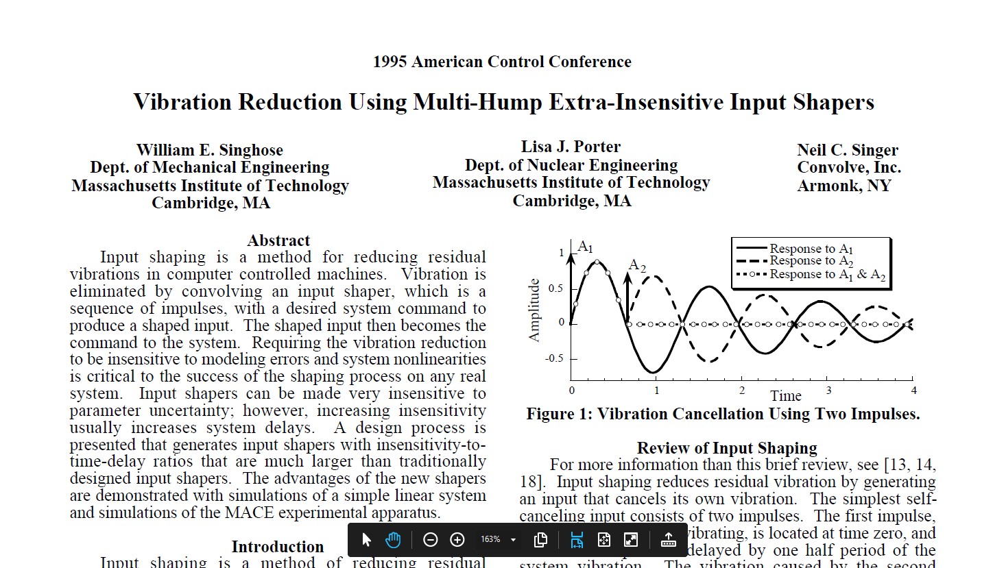
I’m allowed to attach things now! But can’t attach pdfs. This is the 1995 control conference paper. This is a big subject and forums/posts like this can meander. Happy to be corrected or informed if needed. Want to learn about this printer environment as fast as possible… Peter
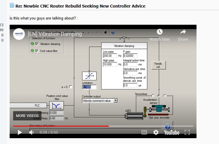
The Rexroth image is snipped from a video explaining how their servos are tuned. It has three options 1) feedback from a position sensor 2) from an accelerometer 3) sensorless, which is input shaping. I’m sure you will know they have been doing this for a very long time. I’m sure this is where Maker level printers are heading. I’m sure professional level printers already, have it? I’ll have to look to find printers that use servos. Peter
That isn’t what is happening at the knees. The time only reaches zero as the V-U also approaches zero. It is a constant acceleration (positive) at the ramp up (the derivative of mx is m). Then a discontinuity to zero acceleration (the derivative of a constant is zero). Then a discontinuity to a constant negative acceleration on the ramp down. The derivative of that kind of discontinuity is infinite. The jerk is infinite. The acceleration is finite. But I don’t think that really matters.
I will take a look at that paper.
Hi Jeff - No I don’t want to get bogged down in the maths details either. We both agree that the knee is a point of high accelerations and jerk so is not good. I think you agree that input shaping is better than no input shaping? Have you heard of the TinyG? It was on my list but I think the printer MBs are the go at present.
TinyG CNC Controller - Synthetos
So to summarise the motion controller space as I see it:
Open Loop solutions
- Trapezoidal velocity planning is easy and conventional but lacking as we get faster due to high accels and jerk
- S-Curve planning uses a clothoid curve (or should use a clothoid) at the traps knee to smooth the transition but this still has issues due to the “fixed” nature of how the s-curve is implemented in controllers
- Next level is something like the TinyG and there are industrial motion controllers that plan velocity to the 3rd order so are technically smooth. But these planners don’t know anything about the machine so could be limited
- Then there are input shapers that measure the machine resonances and use electronic damping to smooth the path or the velocity, which smooths the accel and the jerk (I’m not a coder and I’m not up on how the input shapers are exactly implemented at code/electronic level)
Closed Loop solutions
5) Motors can use displacement, velocity and accel feedback though a PID to use Electonic damping to smooth the motion. This is a good step forward, but more can be done at the controller level before it gets to motors
6) Very advanced industrial path planners use path smoothing, forward path and reverse path optimisation with adaption cycles, 3rd order motion planning the whole shebang to make the path the smoothest possible within the set controller path tolerance. Then the servos do their thing with feedback to produce exceptionally smooth VV fast motion.
As I’ve said before that the printer space is fast moving and agile and they are at 4) Maker CNC is at 1) I come from the CNC hobby space and its motion has not changed in 20 years so it’s time to jump forward! with as least jerk as possible!
Print users will want to get faster and faster so they are one easy step away from the 5) solution and then they will get to 6) when the market pushes them to it.
My interest is in improving my machines motions. My professional area is machine design, structural optimisation, advanced composites, advanced structural analysis. So PID coding, Electonics is a bit way out there for me, that mental area rusted some decades ago… I just want the motion solutions ![]() so I can build better machines. So it’s back to understanding Klipper… Thanks Peter
so I can build better machines. So it’s back to understanding Klipper… Thanks Peter
A long time ago. Looking at it today. It is missing a lot of features of a newer board like the skr pro with tmc drivers. It looks like it is at least 7yo. So maybe it was revolutionary at the time.
I think it depends. In its current form, it will not fix the runout chatter or the tooth passing frequency. It could help if those are not your issue, and you are cutting with such high accelerations that you are experiencing ringing from the gantry motion itself.
But the cons are that it is more complicated. And a bad calibration could be worse than no calibration at all.
The input shaping from klipper, in the video I shared is treating the system like a black box. It sends a range of inputs and measures the response output. If the system changes, the output changes, and Klipper has no idea. If you measure the input shaping without a router, you will get worse results when you add a router. If you measure with a bit in the air, you will get different results when the bit hits the wood.
There may be a category of machine that I would not consider hobby cnc. Something in the $10k-$100k range where the machine is rigid enough and large enough that the ringing from moving the machine is an order of magnitude larger than the noise from the bit. In that case, this could help.
What is the difference between 2&3? A constant (discontinuous) jerk seems like it defines both of these.
-
Is only better (IMO) if the majority of the noise is caused by the motion system. Not if the noise is caused by unpredictable external forces.
-
A $5-$10 open loop stepper motor is extremely accurate until it skips steps. A position fed back into a PID needs to be very accurate and precise to be able to compete. Any sensor measuring acceleration that is double integrated to feed back into a PID is going to fail. Getting position from an accelerometer is way too noisy. Unless you are using very expensive servos (which use precise positional feedback loops), this is a worse option than 1.
This is a counterintuitive opinion, isn’t it? It seems like closed loop has to be better than open. But I have spent a lot of time designing and debugging control systems and position estimation systems. Garbage in = Garbage out. If you can’t get good input sensors, then you can’t get good output. A precise open loop system can be orders of magnitude more accurate than a closed loop system.
- Sounds good. Also sounds like a $100k machine.
There are closed loop stepper drivers:

They are cheap. But my problem is just that the sensors are not nearly as accurate as the open loop steppers by themselves. They detect when catastrophe happens, but they are not as precise the other 99.9% of the time.
Absolutely. The benefits come from excellent communities where people try new things, get repeatable results, critique ideas and are skeptical of results. Tons of new ideas are developed and they are in constant danger. Only the best ideas survive. New features are shared in open source, and can be applied to any of the printers out there.
At the end of the day, don’t let me and my theory get in the way of a good experiment. Just don’t convince yourself they are great by your own theory either. There are a lot of reasons to be excited (the 3D printing results are very good). But there are reasons to be skeptical (the cnc dynamics are different than 3D printing).
A good experiment needs to be derived to show the relative reduction in noise, decrease in total movement time, and consistency in multiple projects.
Don’t accept my bias in the results. And don’t let your own bias affect them either. The results have to speak for themselves.
Go for it.
I just realized that sanitation engineers and water treatment plant engineers must have a different metaphor ![]()
Hi Jeff- Thanks for the discussion and I’m all about testing ideas vs taking them on at face value (there’s around 10,000 on the list to test) . I don’t know a sanitation engineer to ask about their meta language either. Re: chatter - this is fixed by rigidity - if a machine is not rigid enough for the duty it chatters. All you can do is stay away from areas of known harmonics. Poor harmonics are identified via modal analysis at machine design stage then sorted (or in-situ analysed). So onward to testing, first build a small printer to get familiar with the printer tech then move onto a small router with input shaping, then I can report back. Segway -
Re the Low rider. Ryan and team have done a great job with this little router. In the last few years, I have probably done 1000 hrs in small cnc machine design particularly on configuration research and the Lowrider has two elements that have come out strong from that research A) if you use a gantry with the rails mounted on the front a triangular gantry is the best shape. Lowrider has that B) Lifting gantry machines are usually in the extremely big range. By big I mean you can machine large houses or aircraft in them so their Z axis system is really long and wobbly. So they use lifting gantries to solve that issue. They usually have a moving Z as well. There is no reason that this can’t be scaled down and that is what the LR has. These two things make the machine DNA very strong and the videos of the machine cutting prove that. Usually machines with printed parts are quite wobbly due to plastics low modulus. I have stayed away from lifting due to axis limitations in the CNC controllers. But printer controllers have more than enough axes to take advantage of…
Keep up the good work… anything I can contribute with happy to help… Peter
To answer some of your ??? S-curve planning is a compromise like a bandaid on the trap curve, its still a first order planner 3) is a proper 3rd or 4th order planner that produces smooth motion everywhere. The $100k machine is still using trapezoidal with the motor doing the smoothing. A $1M machine is more like it for the motion to be planned in the controller and the motor…
Ryan is a one-man show with a few trusty sidekicks helping in the forum. ![]()
As soon as you know your way around the CNC, you will be able to help. Actually, it goes pretty quickly. Lesson 1: The first thing you ask is “Did you check your grub screws.” That solves 30% of the problems. ![]()
This community is great and if you want to get involved, everybody lets you get involved.
If you want to help in another way, just spread the word, post some things you made here, make a YouTube video, gift your wife a Primo for her birthday. Anything goes. ![]()
P.S.: Are you German? Your name sounds German. ![]()