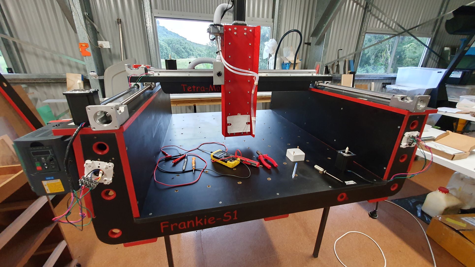
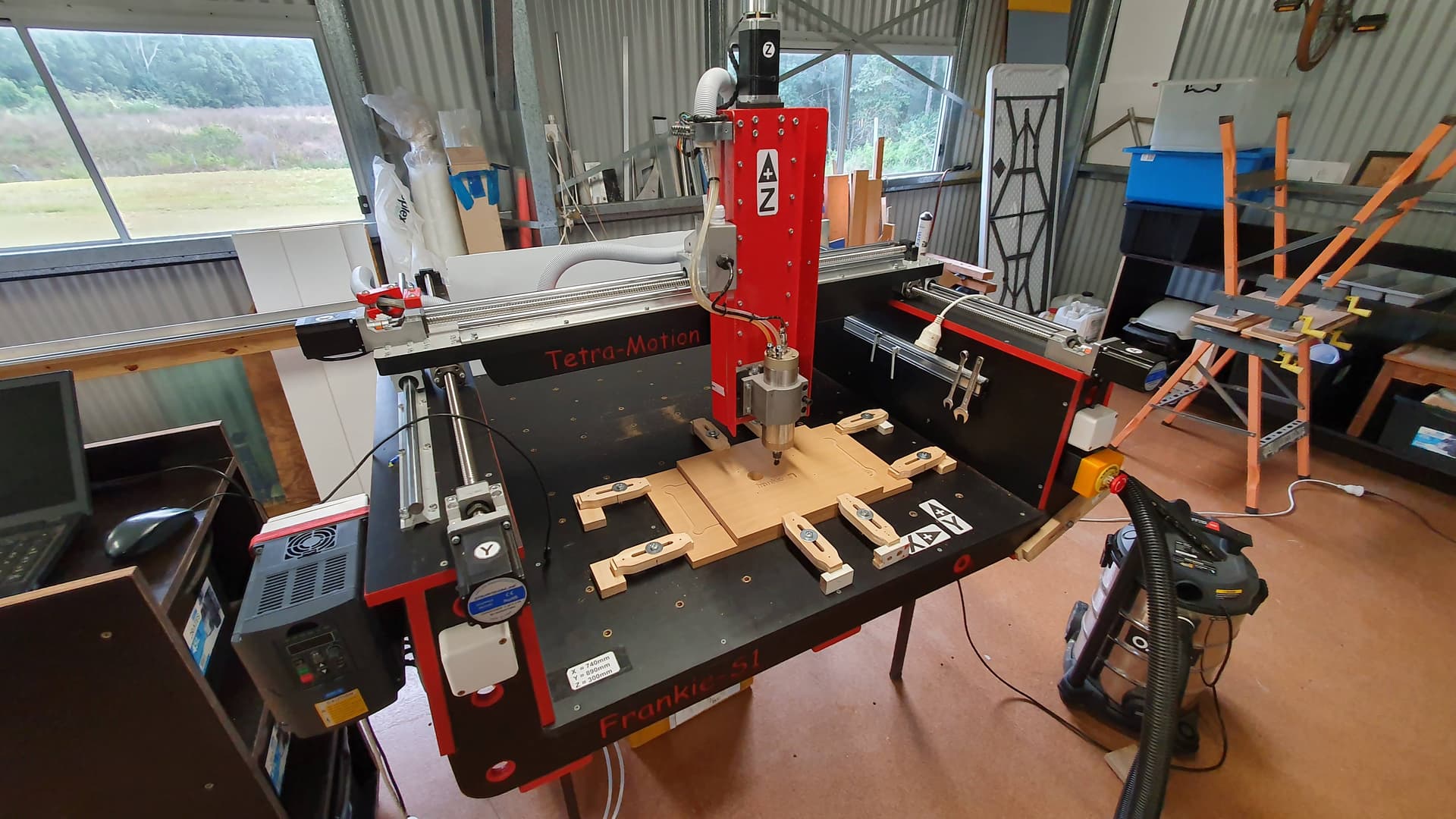
Hi Philippe - Sorry no spreken duetch. I’m about 5th generation OZ ![]() This is the sort of thing I build at the moment… and yes those grub screws can be an issue. Usually I loctite them…Peter
This is the sort of thing I build at the moment… and yes those grub screws can be an issue. Usually I loctite them…Peter
1 Like
Looks interesting. If I’d ever cheat on Ryan I would build the Volksfräse @Unclephil created (Volksfräse VF1 - sir-phils Webseite!, Volksfräse auf Kugelumlaufspindeln umbauen. So einfach geht´s ! - YouTube). Maybe in ten years or so. Now I’ve got the LR3 and it’s been awesome so far. ![]()
Hi, I skimmed through the messages so apologies if this was resolved but I did the low rider v3 with the manta BTT board and klipper. I did the resonance testing and input shaping and noticed very little change to overall speed capabilities or cut quality. My current build has so many other variables to fix before I think I cut at a speed that would see the resonance being the big issue. Having said that, setting it up and adding the compensation took all of 10min so I dont see a down side… I already had the know how, parts, and resources from doing it with my ender. As far as set up, I have a post or two on what I have done and I also started with a config file from another users post on the forum. I found setting up klipper configs very easy if familiar with 3d printing and klipper.
1 Like
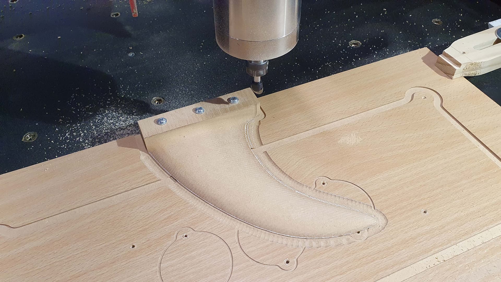
Hi Patrick - Thanks for the feedback. What are your typical cut parameters? feed speed, chip load, rpm etc? material? Frankie has been complete for a while and I sold it to a guy that makes surfboards and surfboard fins. I’m now making a 4x8’ envelope machine. I was going down the path of BTT and Klipper but I’m trying a local controller called Nighthawk on this one. Regards Peter
Hello guys,
I was reading this thread because I was also genuinely wondering if input shaping could potentially be beneficial to partially mitigate lack of rigidity in low end CNCs.
Your point of view seems quite logical to me @jeffeb3, yet I was thinking that the input shaper could be tuned not only based on X/Y gantry moves, but based on adaptative toolpaths in X and Y direction.
This way the Input shaping would take into account, for a given depth of cut / speed, the real disturbance cause not only by gantry vibration, but also machining forces.
In that case, what would prevent Input Shaping to be effective ?
Even if the disturbance is perpendicular to the axis, meaning that the oscillation is in Y while moving the gantry on X, the software could compensate by affecting Y as well, making the Input shaping compensating both transverse and longitudinal waves if we can say so.
Am I missing something ?
Adaptive toolpaths ot trochoidal milling is done in fusion 360 or estlcam. The toolpaths that get to marlin/grbl are interpreted just like any other. The firmware won’t have any idea that the front half of the circle is a cut and the back half is a travel. The firmware also doesn’t know if you’re cutting into MDF or foam or steel. The firmware (and often the CAM, because of variance in materials) doesn’t know if you’re making a deep cut or a shallow cut.
Any compensation to try and adjust based on the forces in that cut would be really difficult and probably impossible (imho).
You could still run the bit through the air. Any wobbling from the gantry alone could be compensated for. But when it hits the material, I am not sure if that would be better than nothing or not. My gut tells me it wouldn’t make a difference at the speeds we use.
I don’t want to discourage progress. I am wrong all the time. So please prove me wrong.
I just do not see the repeatability in CNC to do input shaping. The 3d printer, that is a given set of circumstances. Nothing changes resistance, nothing changes tools, etc.
In my opinion, which I am wrong around here alot, you would need to run Input shaper with a load, and how would you do that, as it shakes insanely to get the resonance. Chatter would cause problems too. Too many variables. Printhead is always same density and resistance. Tooling changes. Just my 2cents.
Mmh, maybe my idea was not clearly expressed.
I was thinking : Would it be possible to record accelerations while cutting a dummy coupon of a given material ?
The toolpath would be known for that dummy milling operation, with both X and Y moves and combination of X and Y.
This way, by milling a dummy coupon we would have a sample of cutting forces induced vibration for a given set of parameters e.g. X or Y move, speed, feed, DoC, material of the coupon.
As such, we could leverage input shaping for that particuliar set of parameter during the real cuting operation.
Is it a dumb idea ?
my reply would still be the same, I do not see the benefit. I see every day when porosity hits and circumstances change, now that is industrial milling. But a Knot in wood, etc, it all changes. I still do not see the benefit of using Input shaping, nor can it record the affect.
Maybe I am just missing the boat.
I am not sure. It seems unlikely, because the forces would be so different just on the cutting and traveling parts of the circles.
Hi All - I think many people misunderstand what “Input Shaping” is. Input shaping was originally developed for CNC machining not printing. It was developed around 1995 by MIT. It is a passive approach to machine vibration control. It firstly identifies the machines main resonances and then uses an algorithm to modify the impulse train to the axis to mitigate the vibrations around those critical frequencies. This is very similar to how noise cancellation works by placing an inverse signal on the control signal. If you want active vibration control that’s a different kettle of fish. Active means that the control signal is modified in real time (or as a CAM post process) via an algorithm that uses accelerations (measured in real time via an accelerometer) or measured ort calculated velocities to smooth the signal train. This is usually done by calculating the engineering jerk values and modifying the pathway of the tool or the acceleration of the tool to create a “smooth” acceleration path.
search for “vibration reduction using multi-hump extra-insensitive input shapers” for one of the first papers on the subject
So input shaping is about identifying the machines mechanical responses and moderating that, not measuring the tool inputs and modifying them. The input shaper once enabled does not consider the mechanical inputs of the machine ie its mainly a passive system.
1 Like
close older topics to help with spambots, and faster new user questions.