Hurray! I managed to cut the YZ Plates in 3/8" aluminum (and previously the XZ Plates in 1/4" aluminum).
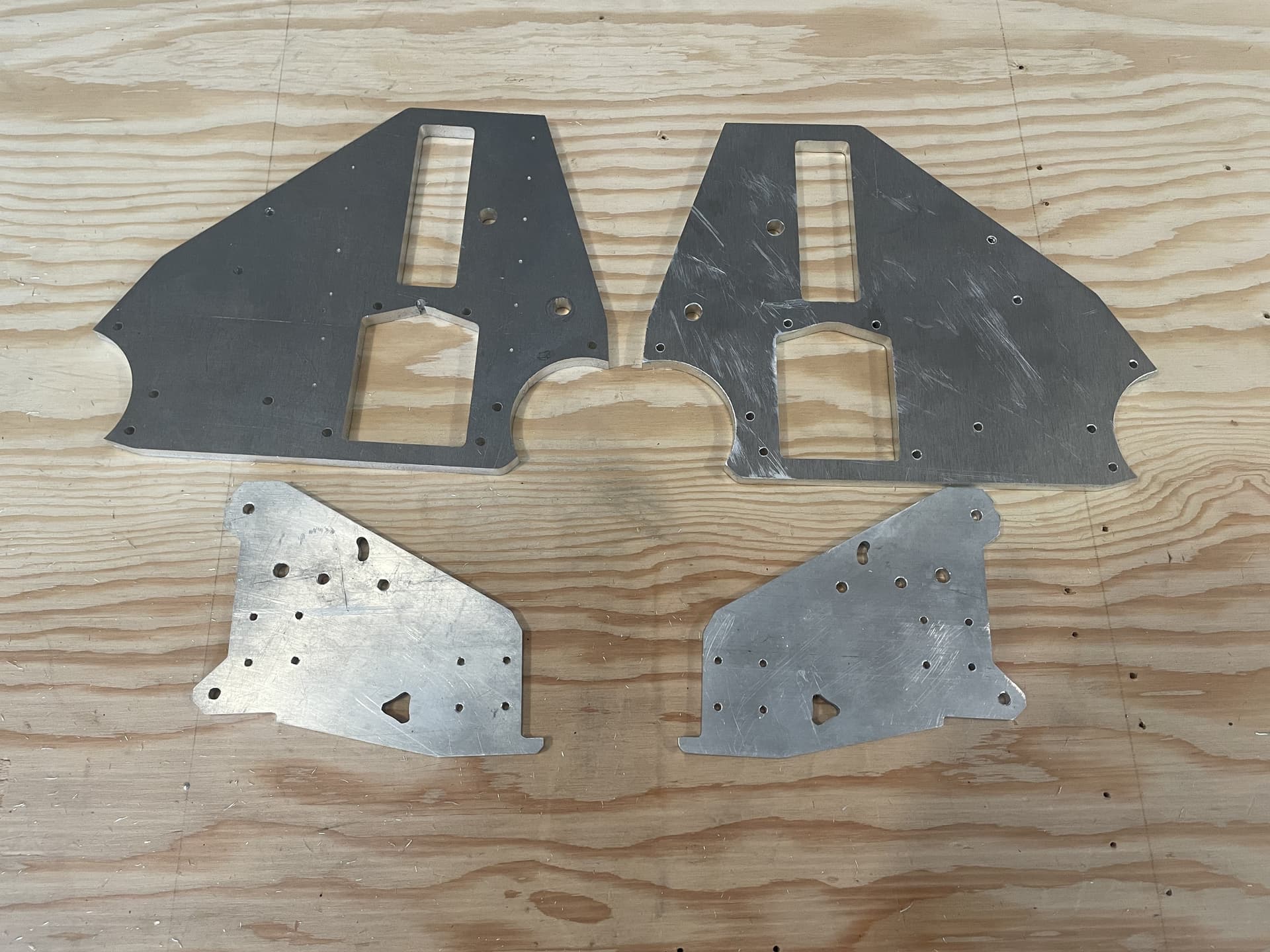
It may not seem like a huge deal from a distance, but I am pretty stoked to reach this milestone!
From where I left off previously, I swapped out the end mill with a nice shiny, sharp one, added a few hold down screws to the sections that would be cut out, and dropped the feed-rate and router speed down just a tad. It cut through like butter on a single pass (well two, if you count the finishing pass), although there were a few issues. They say that we learn from our mistakes, and I must admit that there was a lot of learning and a lot of mistakes along the way…
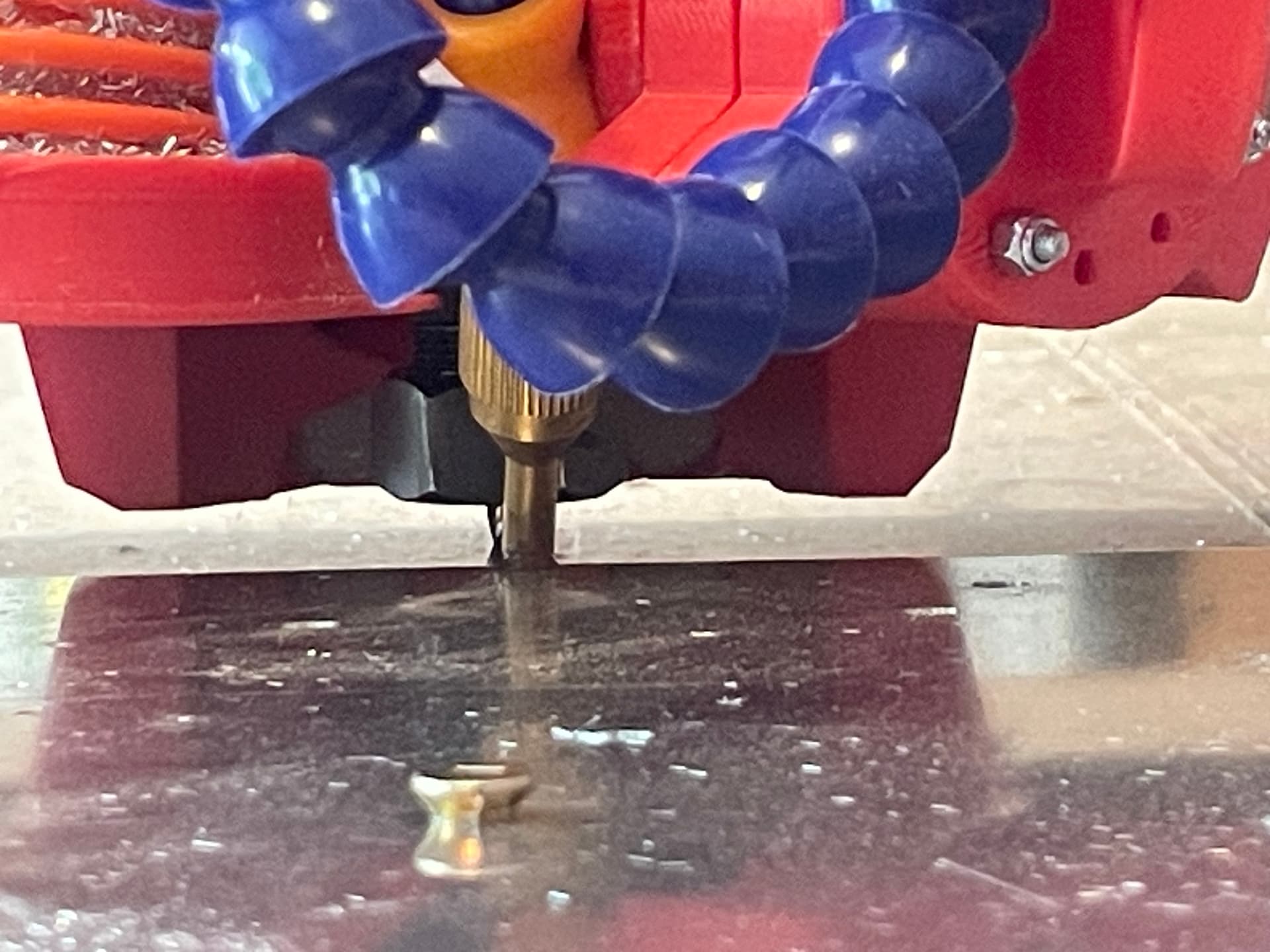
Issue #1: Because of the thickness of the plate (3/8" or 9.5mm), the air mist nozzle couldn’t really reach the slot, so chips were getting stuck in the cutting area, packing in, and causing a lot of re-cutting. This seemed to be worsened a little bit by the IPA mist, which moistened the chips enough so they clumped together, rather than blow out individually.

To mitigate this somewhat, I added a splitter to my air hose system, and used a hand held air nozzle to intermittently (every few seconds) blow the chips out of the slot. This seemed to work okay, but I had to remove the vacuum dust shoe in order to reach the cutting area with the nozzle, so there were aluminum chips EVERYWHERE (and blown even more places by the air nozzle).
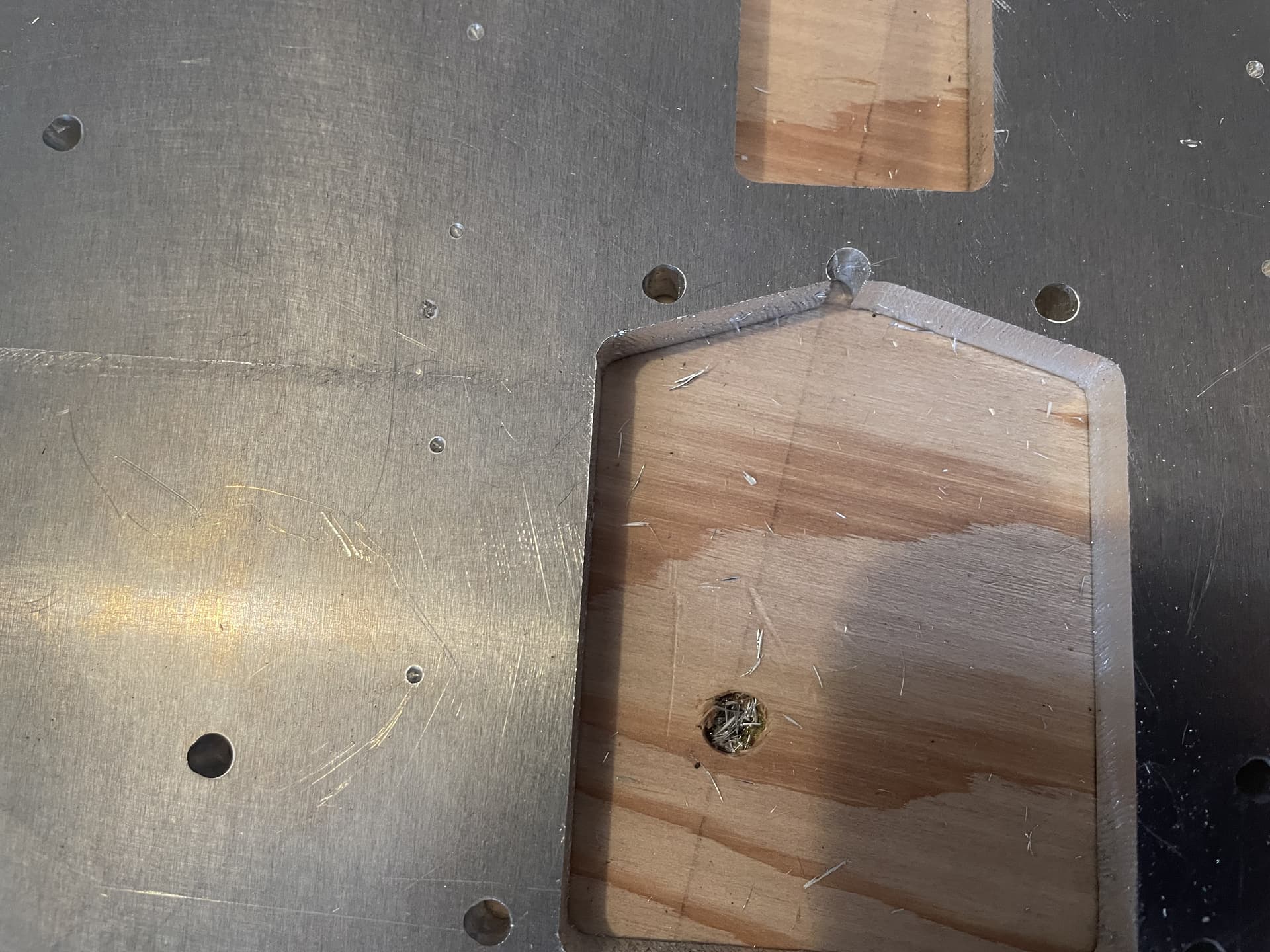
Issue #2: In an effort to reduce deflection, I “choked up” on the end mill so that there were only about 13mm sticking out. The problem was that this meant that the core was only about 1.5mm above the stock, and the previously mentioned hold down screws were sticking up about 2mm from there.
The results were somewhat predictable:
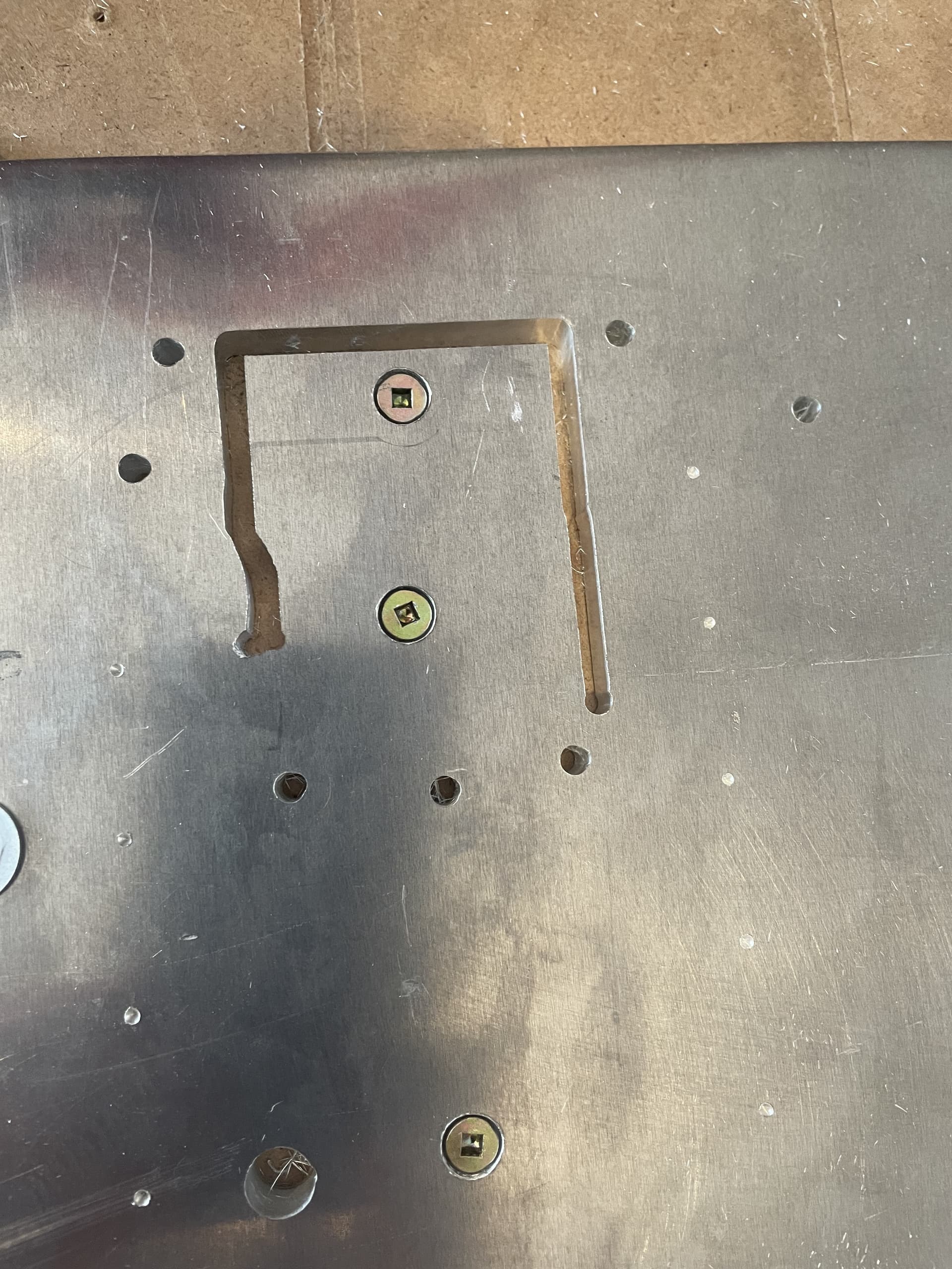
So to correct that I used a drill bit to chamfer the holes so that the screw heads were flush with the stock, and increased the stick-out length to around 17mm.
Issue #3: When I added additional holes for the hold down screws to the design in F360 (couldn’t find a way to add them in EstlCAM), I imported the new design into EstlCAM with a different orientation than the original project.
Original:
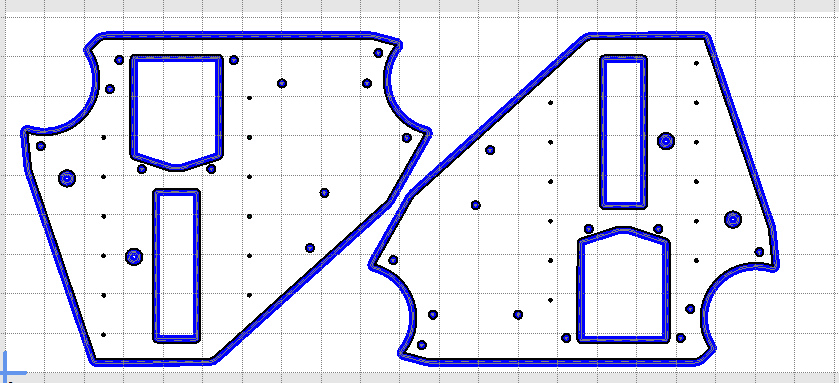
New:
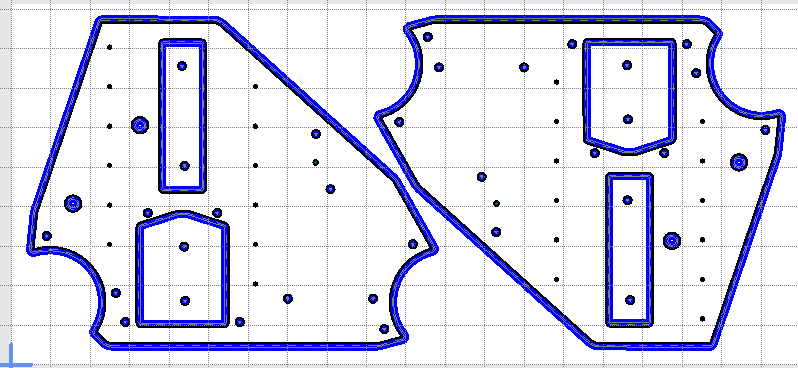
I was originally planning to redo the whole cut using a new piece of aluminum, but then decided to continue cutting the same piece, not realizing that I had flipped the design. I ended up only cutting one hole in a place that it shouldn’t have been before I noticed this and stopped.
I haven’t decided yet if I will re-cut both plates using new material, or live with the imperfection as a reminder to check things twice before restarting a cut. If I go the second route, I could probably use some metal epoxy to fill the gaping hole so that it doesn’t look quite so glaring.
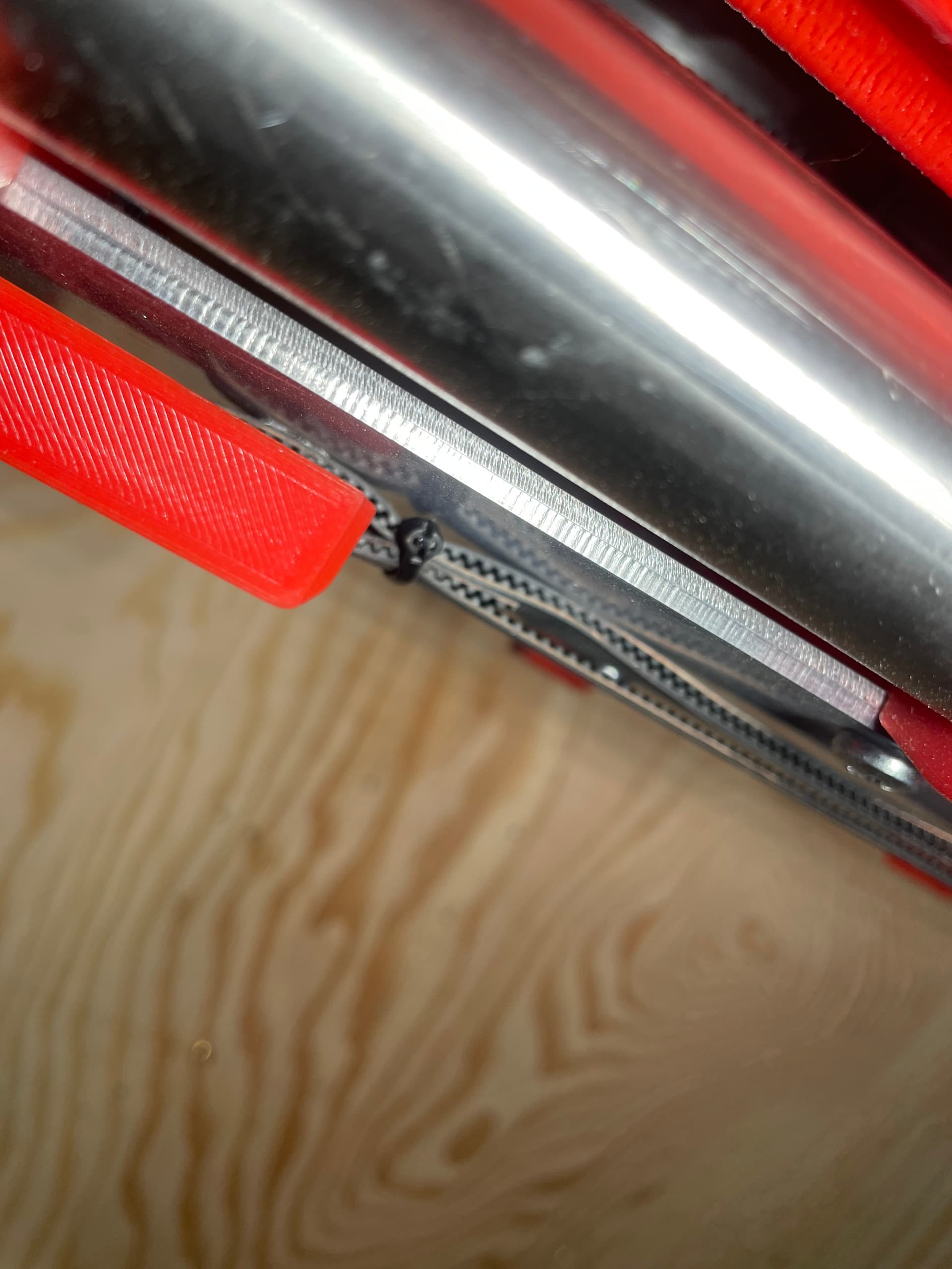
Issue #4: This iteration of the LR3 is a smaller, temporary stage on the way to a much wider build. Because I am a cheap bastard at heart, I decided to not cut the X belt to length, so that I could use it later for the larger build. I routed the slack along the front strut, but this meant that there wasn’t anything other than friction holding the belt from slipping. Well, the forces from cutting eventually overcame the friction forces, and the belt slipped in the middle of the cut. Fortunately I caught this fairly quickly (another reason to never leave the machine unattended), and there was no damage to the material. I had to reposition the belt a few times until the end-mill fit nicely into a marker hole that I had previously drilled into the spoil board at 0,0,0. Then I used a small tie wrap to secure the belt and the slack together, hopefully preventing any future slippage.
Issue #5: I noticed after pausing when the loose cut-out piece moved and jammed (post #137) that the holes nearest Home were nicely through cut, but the holes farthest away from Home on the X axis were not cut all the way through. I did a measurement of the gantry at each end with a telescoping gauge, and found that I somehow forgot to adjust the Z end-stops prior to now, and they were out by at least a couple of mm. I adjusted them and all of the subsequent cuts were pretty much even and all the way through.
So combined with the failure to secure the cut out pieces as mentioned in Post #137, that is pretty much an even half dozen issues overcome while cutting the 3/8" aluminum YZ Plates.
I’m getting quite a collection of broken and damaged end mills along the way.
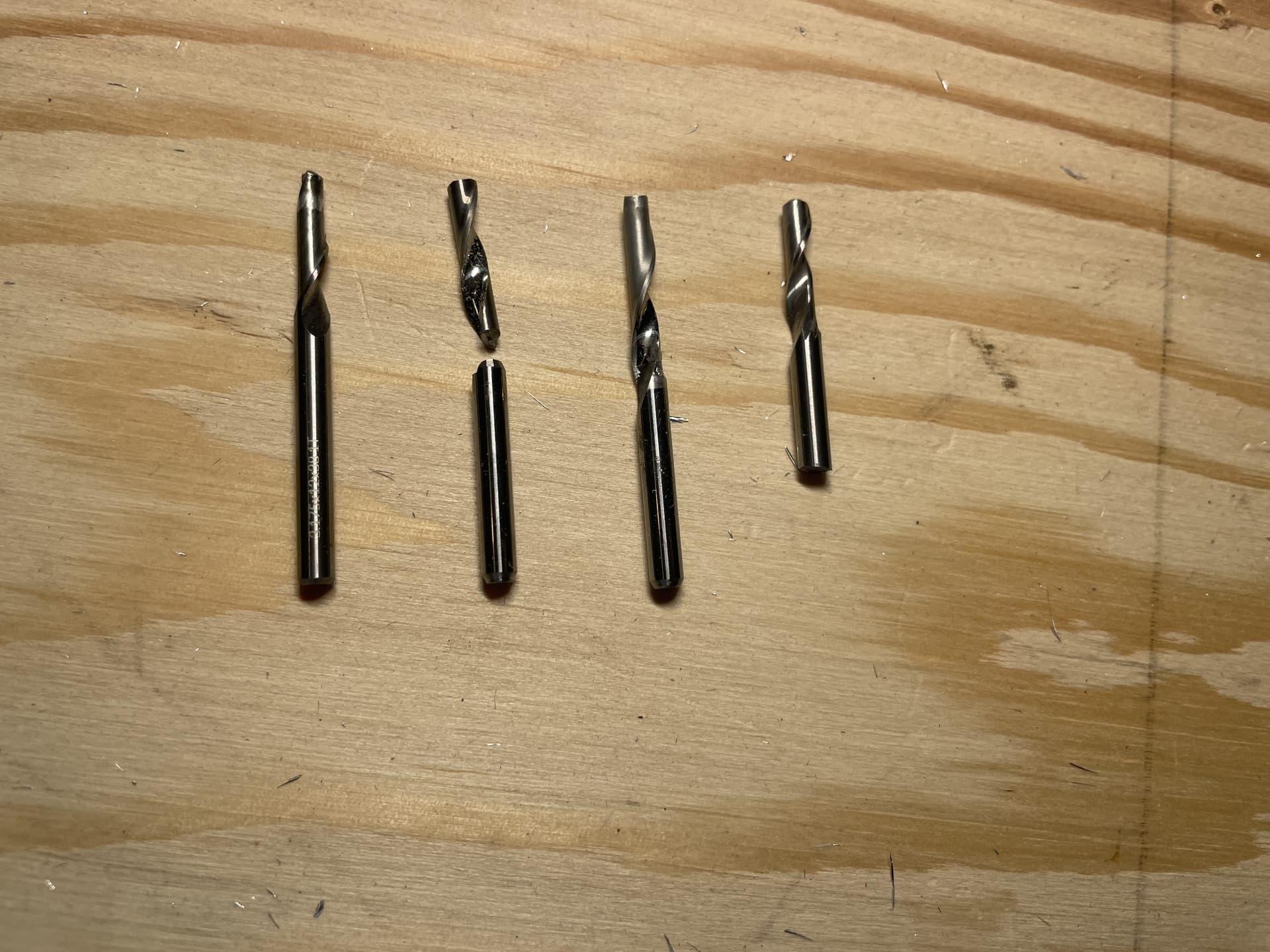
From left to right:
#1: Aluminum welded onto end of mill when insufficient clearance plane caused the mill to jam into 2mm plate during cutting of strut (Post #126)
#2: Mill broke when it jammed into material due to insufficient core clearance from hold down screw (this post).
#3: Dull and some minor aluminum welding after mill jammed into material after failing to secure cut out pieces (Post # 137)
#4: Mill broke when it struck a small rock chip embedded in the hardboard spoil board from the factory (Post 129, although I didn’t discover the cause until later, so it is not mentioned there).
So next up is to disassemble the current small LR3, and assemble the full size version. The more observant of you may have noticed the lack of a hole for the Y motor on the YZ Plates. That is because I intend to use @Fabien’s side mounted belt design (LR3 Side-mounted Y belt - #22 by Fabien).
That will throw a bit of complexity into the cutting of the rails and struts, as the width between the XZ plates now depends on placement of the side mounted belts, the thickness of the YZ Plate and the thickness of the XZ Plate. The LR3 Calculator isn’t able to factor in all of those variables, so I will probably have to partially assemble everything, then do some careful measurements while the parts are temporarily held in place.
Whew - seems like time for a beer break!