Aussie LR3 Build

I’ve been collecting parts over the last few months, waiting for my 3 weeks off over Christmas/new years to put it all together. I got the table done to the point I can work on it, and started assembling lowrider parts today, so thought I should start a build thread.


I printed all the parts myself on my previous project, a custom built 3d printer. These are the first things it has printed. Safe to say I underestimated that project. It ended up taking me at least 18 months to complete (with a few months break here and there). I’m happy its done and its definitely a heap more capable than my Ender 5, but if I was to do it all again I would just build a Voron or Ratrig and get an even better machine for a similar cost and a heap less work (but maybe not as much fun).

I had the XZ and YZ plates both water jet cut from 6mm aluminum. I tapped M3 threads to mount the linear rails and used M3 x 10mm cap screws to secure them. If it had of been 1/4" (6.3mm) aluminum they would of been the perfect length as they protrude just slightly on the back side, but I don’t think that will matter.
I also considered tapping M5 threads for the Y drive / Z drive / endstop mount, but I ending up drilling them out to 5mm and I will stick with the nyloc nuts (so they don’t come loose).


6 Likes

Nice setup Daniel, very cool! I was going to ask how much the waterjetting was then I read in another thread that you have a mate with access!

I’m looking forward to seeing it run!

1 Like

Looking good!

I ended up going with a cutting area of 1250 x 1800, leaving a little bit of wiggle room around the table.

Waiting on a couple of parts I forgot to print. Then just need to finish off the table (mounting strips down the sides and spoilboard), finish putting it together and wire it up and I should be able to cut my strut plates.

Does anyone know of anywhere in Australia that stocks the 1/8" makita collet and 1/8" endmills? The only place I found (Adams Bits) is currently out of stock. I know I should of been more prepared, but I don’t want to get stuck for weeks waiting for them.
Alternatively can I cut the strut plates using a 1/4" bit?

2 Likes

I never found it somewhere else but https://elairecorp.com/makitaroutercollets/ or Ryan’s shop, which are the ones from Elaire as well.

1 Like

You could check;

  • Sienci labs
  • 3dtek
  • v1 shop

If there’s no reason not to buy at Ryan’s shop, I’d buy it here just to support him.

I bought mine from Ryan @vicious1 - postage wasn’t cheap, but delivery to the Sunshine Coast was faster than it would have been from Melbourne!

Where are you in Aus?

1 Like

delivery to the Sunshine Coast was faster than it would have been from Melbourne!

Why does that not surprise me. I’m in country Vic.

3Dtek have them but are out of stock as well.
I’ve ordered from Ryan and we will see which turns up first - across the other side of the world from the states, or from Adams Bits an hour down the road from me.

2 Likes

Just a little too far to drop one over for a loan to get you going! Even express mail you won’t have it till Friday at the earliest! Ahh well - I’ll keep watching your progress with some enthusiasm.

1 Like

Hello Daniel, I am from Rowville Victoria. Question about your XZ plates. Is 6mm aluminium a safe bet for rigidity? and what was the cost of getting the plates cut? regards, David

I think I just replied to your other thread without seeing your reply here.
6mm is plenty, I’m very happy with how they turned out.

They didn’t cost me much because my brother has access to cut them at work. I’m unsure what they would of normally cost, but if its not too much I would highly recommend it.

2 Likes


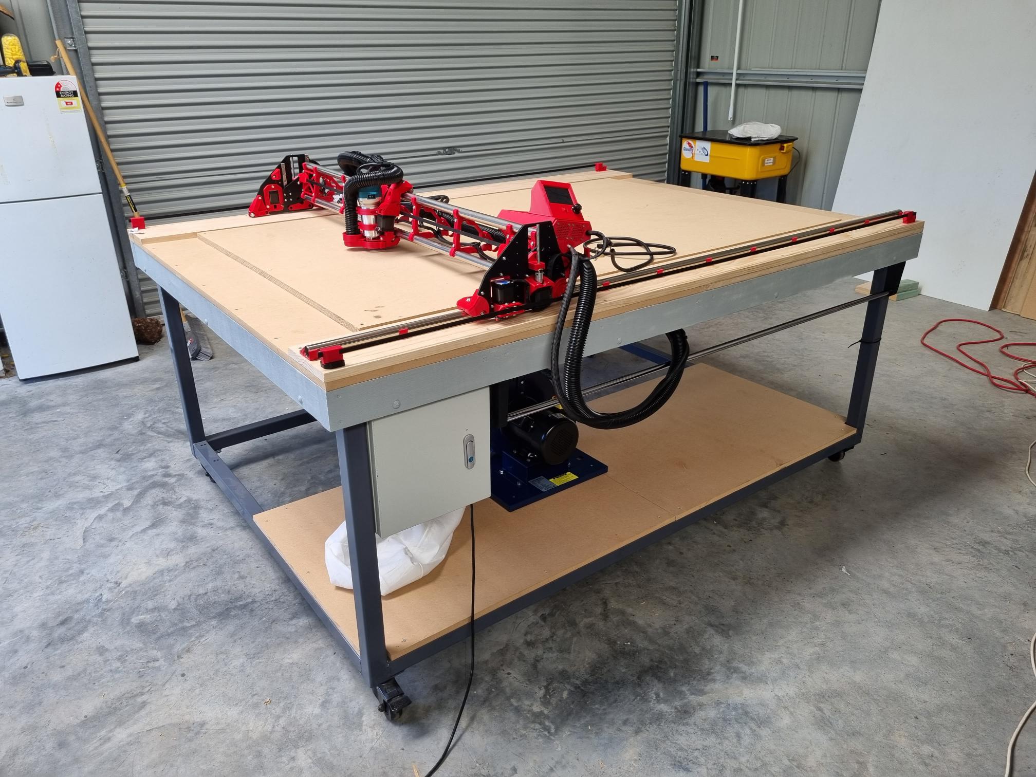
Finally got it all together and working today to the point I hoped I could cut my strut plates. I ended up printing an adaptor to use my smaller vacuum hose. Mounted the dust collector under the bench.

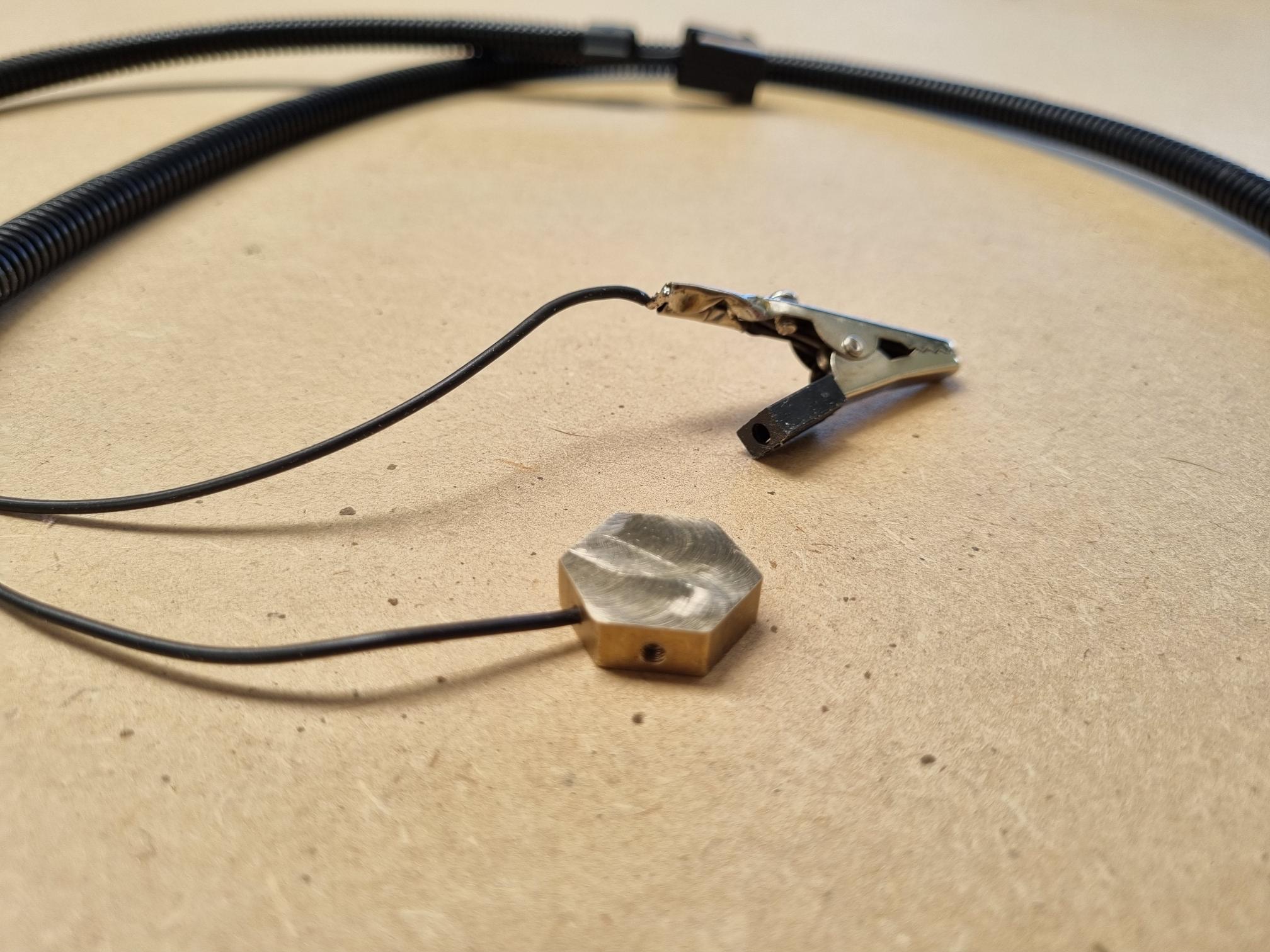
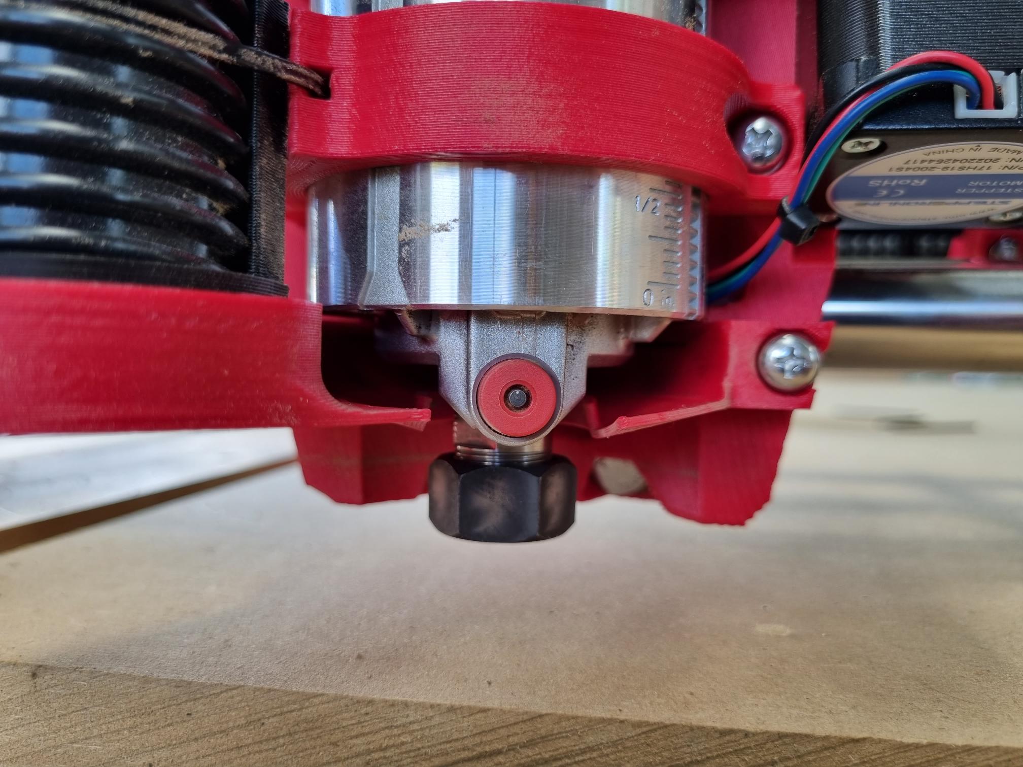
Also machined up a probe from some brass hex stock. The wire is secured inside it with an M3 grub screw. All up its exactly 6mm thick. And having a little bit of weight it sits flat on the bed.

I got the machine squared up in X/Y. I spent a bit of time making sure the Y2 belt base was positioned square to the rail when I screwed it on, so the machine was less than 2mm out of square when I first checked. Better than I had expected.

I did the Z leveling using my new probe. It wasn’t too far out either, but got it to within half a mm, which seemed to be about as repeatable as I could get it. I assume the spoilboard isn’t perfectly flat.


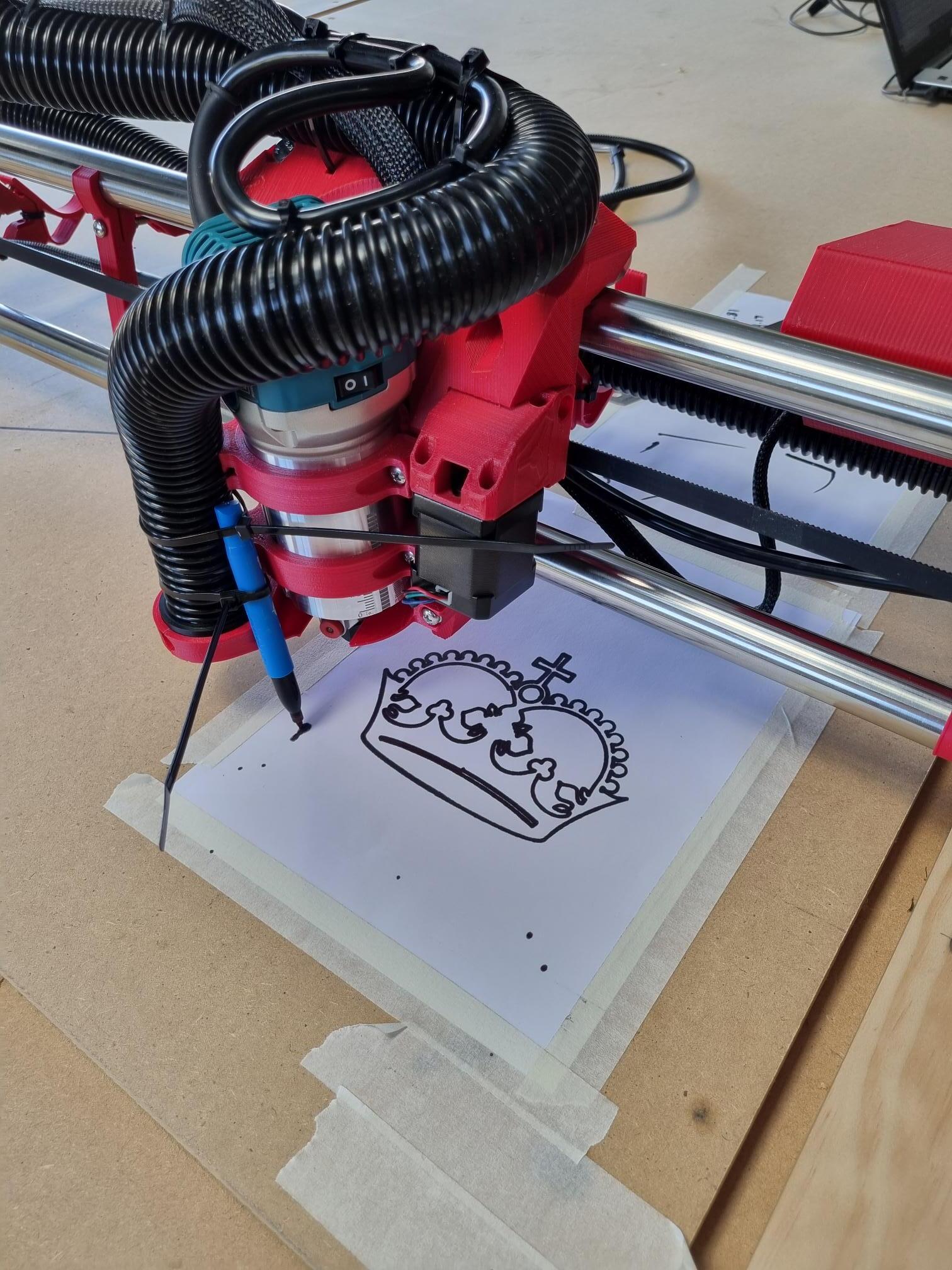
I seemed to be more difficult than I thought to get the crown to draw correctly. There seemed to be variation in the Z height between Xmin and Xmax ends of the crown. Sometimes one side wouldn’t be touching the paper at all, and the other side was dragging the texta very hard into the paper. Went back and checked Z leveling a couple of times. Probed and made comparisons between the 2 sides of the paper. Everything was saying its within less than a mm, then other times it was 2mm out (over the 150mm of the paper, yet the whole X axis was less than a mm out when Z leveling?). Spent a couple of hours trying to sort it out and then gave up and went onto my strut plates.


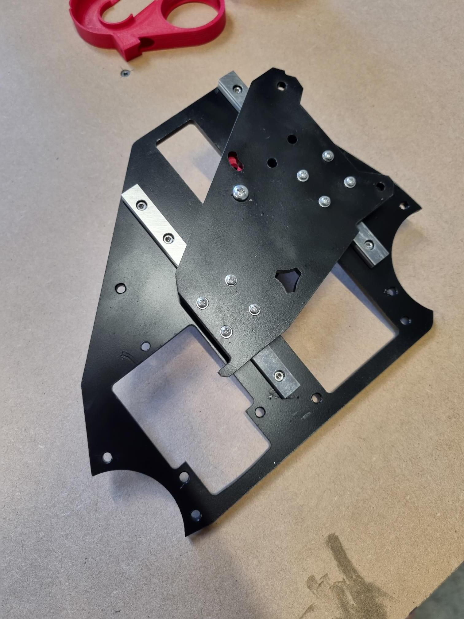
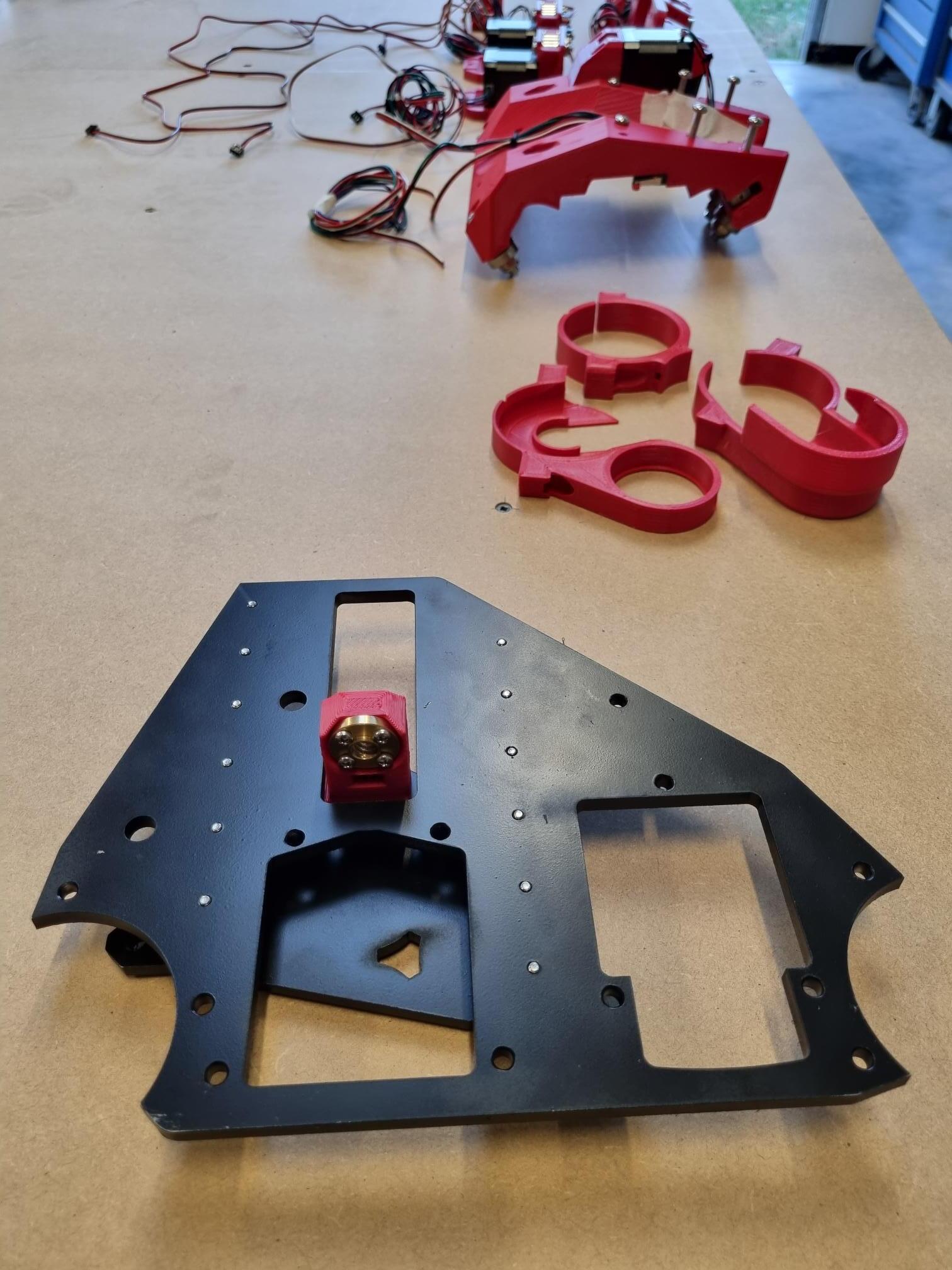
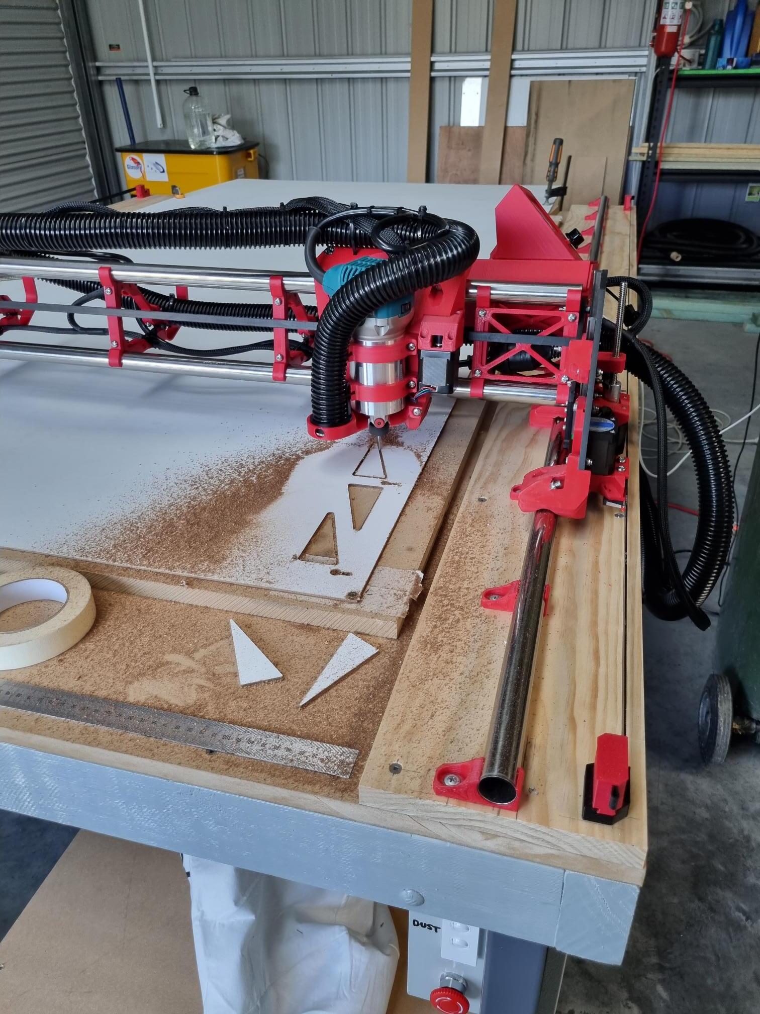
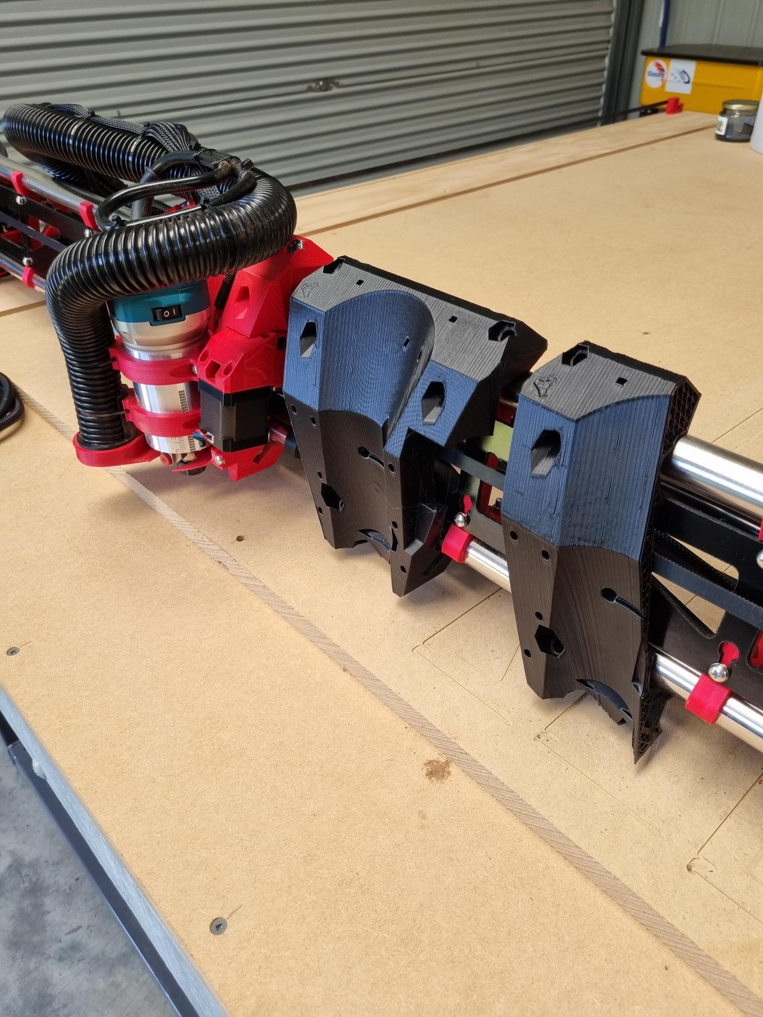
Strut plates started off great, except I forgot to put the dust cover on before I started.
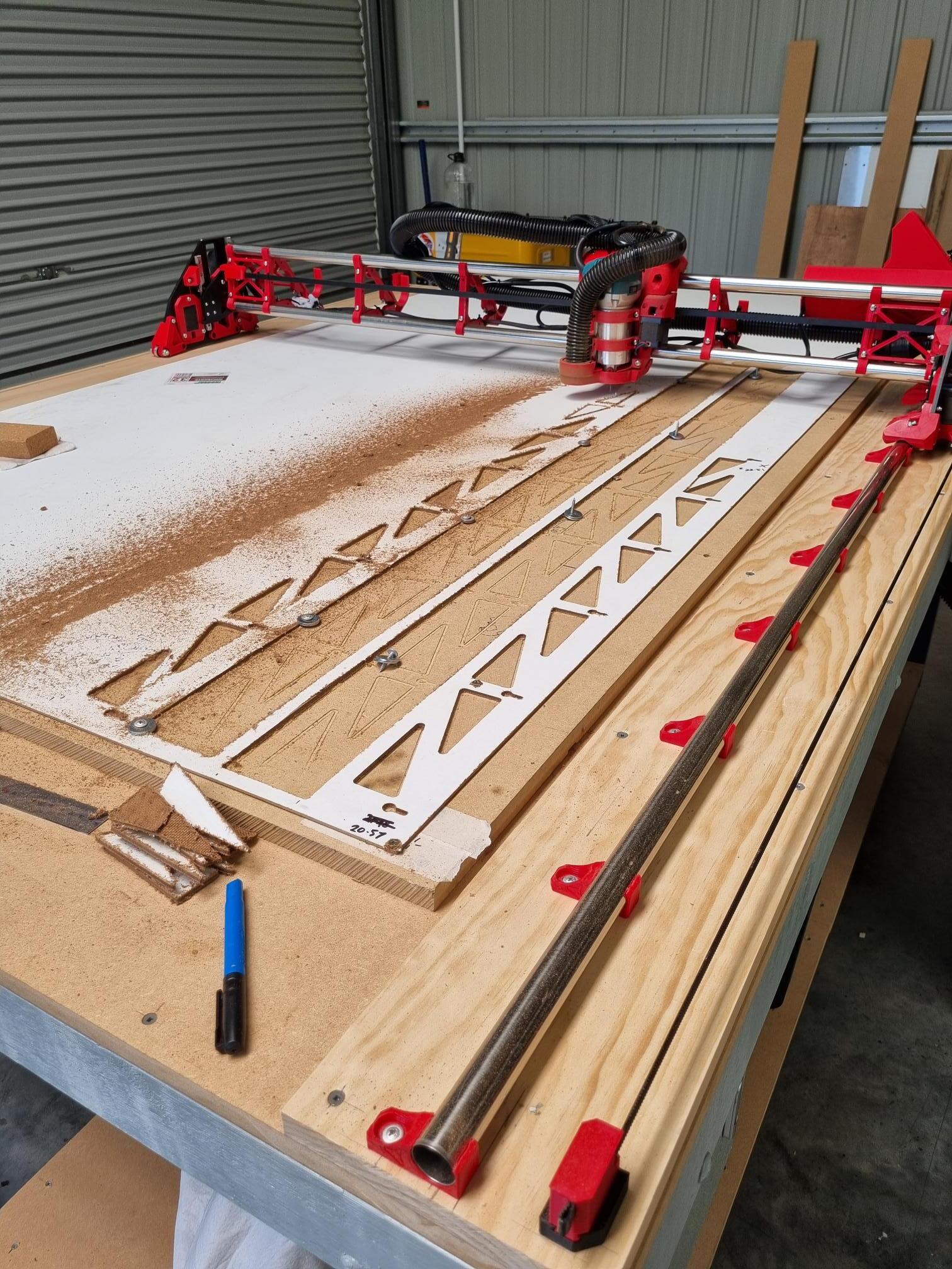
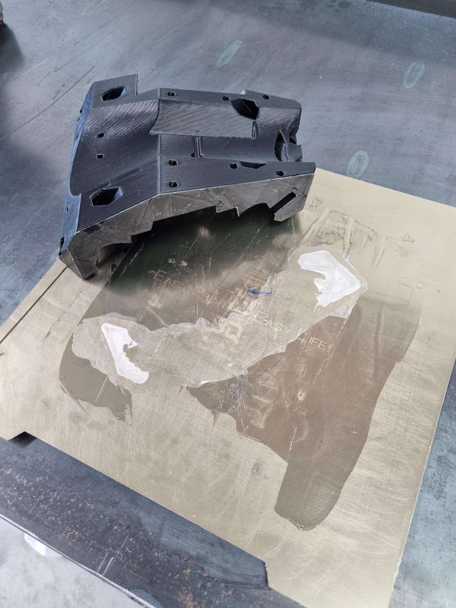
Made it about 3/4 of the way down doing the inside holes, and I noticed it seemed to be cutting deeper and deeper. The holes were loose and free by the second pass (it should take 3 passes to get right through the entire 3.2mm thickness) and I was cutting deep into the spoil board.
By about 3/4 of the way down, the bit was cutting between the sections when it was retracted and moving to the next one, so I switched if off.

Before I moved anything I wanted to know if the Z axis was dropping or if the table had a massive bend in it (I didn’t think it did).
Powered it back on, moved 10mm over so I wasn’t on the cut anymore. Homed Z right there, and then probed and recorded the Z height. Then moved back near the start of the cut, homed Z and probed again. There was like 0.8mm difference, which I thought was reasonable since I haven’t surfaced the spoilboard yet.


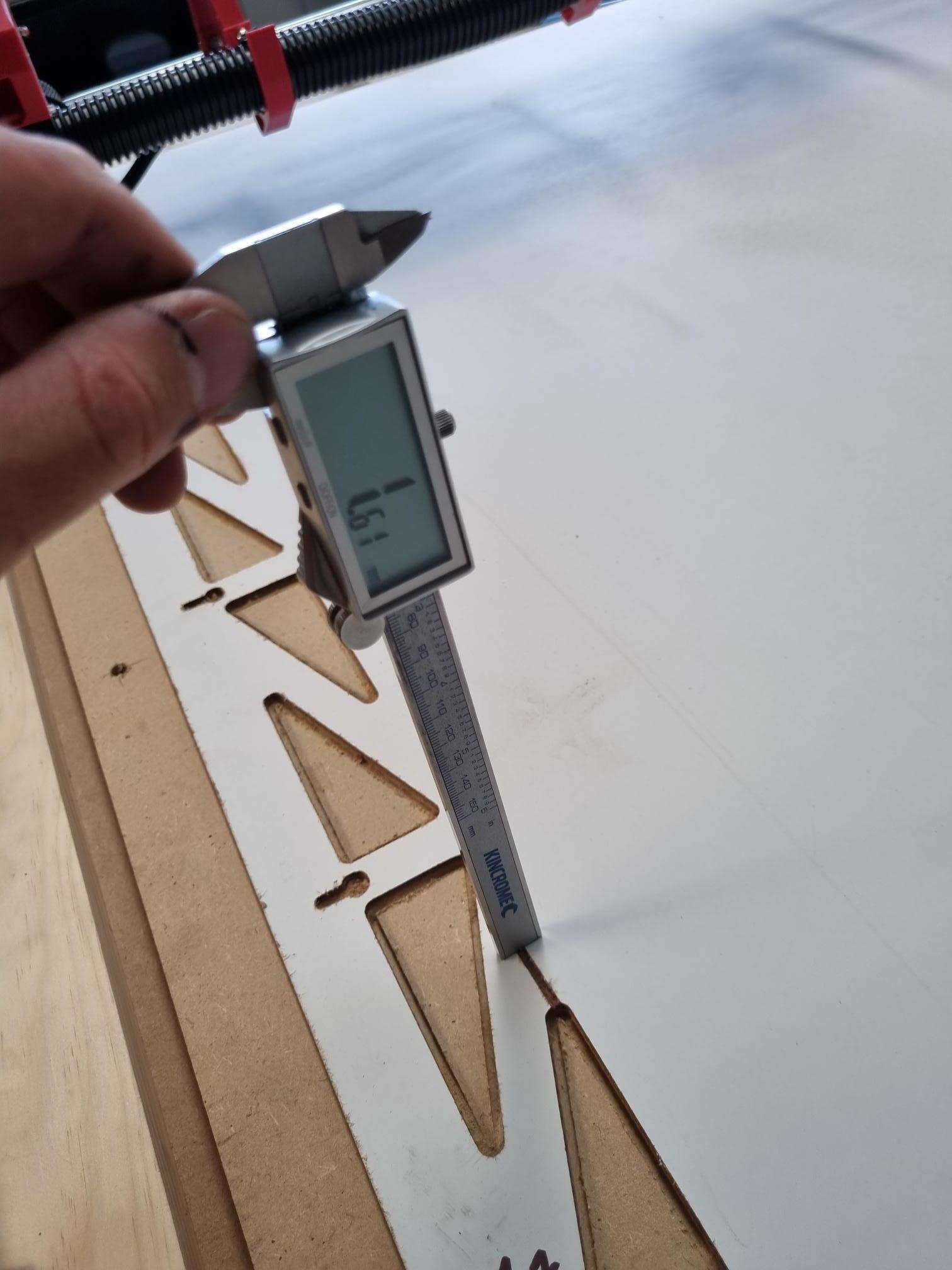
I measured the depth of the groove left between the 2 holes (which should of been with the tool up out of the way as it travelled overhead). It was about 1.6mm. I’ve got the clearance plane set to 2mm in ESTLCAM, and assuming there really is 0.8mm variation between around that point and where I started it (as the probing said), the Z axis had dropped at least 2.8mm by the time it has got here.

If the gantry is to one side, the Z axis drops immediately under its down weight when I switch the power off. I noticed I didn’t update the driver current settings when I was playing with firmware (I thought I copied everything over from the V1 configuration, but obviously not) and both Z motors are still set at the default 800mA. I’ll bump that up tomorrow and have another play around with the texta, and see if the Z axis is still falling.

2 Likes

If it is dropping bit by bit, the collet might be loose.

Impressive looking build! Nice work! Hope you get your Z dropoff issue sorted!

In addition to Phillipp’s suggestion to check collect, another possible cause to check is lose grub screws on the lead screw(s). Tables can have a lot of variance — even (in my experience) after flattening the spoil board, somehow.


Bumped up the stepper current. Reduced the Z acceleration slightly. Lubed the lead screws, I found another post where someone was having the same trouble and lubing the leadscrews fixed it. I did notice mine occasionally squeaked when turning, I guess all the weight trying to turn the other way and no lube and they could of skipped steps. One of those 3 changes definitely worked, because I then successfully drew another 5 crowns without issue and then cut the 3 strut plates.

I checked the temperature of everything with my heat gun after the 3rd strut. Steppers were sitting about 45 deg C. Stepper drivers and the router itself were up around 65 deg. It was a fairly warm day (30 deg) but I guess I don’t want them much hotter on the PLA.

Dust collection still needs work. I need to get bigger hose (48mm instead of 38mm), and something more flexible. What I have is hardish plastic and doesn’t like to bend well to sit down in the hangers properly. Be buggered if I can find any 48mm for sale in Australia though.
I think I need to seal up under the router a bit better between it and dust collection area below it. The exhaust from the router fan that sneaks through seems to be blowing it everywhere harder/faster than the dust collector can suck it up. It picked up a lot of the fine powdery stuff but didn’t get anything of the bigger stuff.

Its currently back in pieces so I can fit the strut plates.

1 Like

I’ve wondered about the vac hose often- bought one from LeeValley in CA and hang the expense! I have thought about using pool vac hose though,

On another note, I designed a block out piece for the bottom of the Makita which seems to work well redirecting the exhaust on the LR2 it’s in this post makita infill. If you are interested in trying it I’ll upload the STL - I haven’t tested it on the LR3 so haven’t published it.

1 Like

I learned the hard way that hose made for water may be unusable for air. Hideously loud screaming shrill whistling sound! Deafening.

2 Likes

Put it all back together with the new strut plates today. In the process I think I found something else contributing to the Z sinking, I noticed the lower dust shroud part was all warped. The router is also loose in the tool mounts (I can rotate it) and seems to have fallen down slightly. It definitely wasn’t like that previously as I had a bit of trouble making it fit inside them (had to back the screws way out to get it in, and it was nice and tight).


On closer inspection I found the core was also slightly loose on the rails. Thought it might of been because I had it apart to fit the strut plates. Cranked the lower bolts up pretty tight, pretty well crushing the bearing they are running through, but still only 1 of the back bearings turn as you slide the core along the rails (the other isn’t making contact with the rail at all).

Looks like the tools mount and core are heat effected and will be going in the trash. I did check the temperature of everything after cutting the strut plates with my thermal imager as I was worried this would happen. The router body was 65°C (150°F) when I was done. The ambient temp was around 30°C (85°F) which isn’t anything unusual for a summer day here. I wonder how bad they would of been if it was a really hot day (40°C +).

I used 3Dfillies PLA+ to print everything (which I’m now regretting). It’s from a company here is Aus, it’s the first time I’ve used it, and everyone seems to rave about how good it is on local Facebook groups. I had a horrible time with their red stuff - constantly having to dry it to stop it stringing and blowing bubbles. I have noticed the black PLA+ I got is much nicer though (it’s been sitting on the printer for a week uncovered and is still printing parts for me fine right now).

Has anyone else had trouble with stepper or router temperature ruining their parts? Is my router getting excessively hot for some reason? I had it up around 4 or 5 out of 6 on the speed dial, because I did read running it too slow for too long will cause it to get hot. Should I just run it flat out at 6?

I think I’m going to attempt to reprint these parts in ABS (haven’t done much with ABS yet, so its going to be a bit of trial and error).

I mostly run mine on 2-3 most of the time, it’s never got too hot.

2 Likes

Successfully printed an ABS core! it took 2 attempts, the first one was warping quite badly by half way and coming unstuck, so I cancelled it and started again.
I’ve always had adhesion issues with this PEI sheet. So I decided to give it a light scuffing with some 800 grit sandpaper. Also made up some ABS slurry with acetone as I’ve read that is the best you can use.
The second one turned out much better. Still very minor warping at each end, but its not noticeable and I don’t think it will have any functional impact. I didn’t even notice it had started lifting until it was finished, and I noticed it had actually lifted the PEI coating from the spring steel plate (so there was definitely no adhesion issue between the print and PEI this time).


I thought I would get the hardest part out of the way first. With that done the tool mounts should be fairly straight forward.

Also found some better dust hose locally (Dust Collection Hose (PVC, PU) – Aaron Group Australia)
It’s 50mm but I think it will be close enough to 48mm to work, I’ll make up adaptors if necessary. Also looks much more flexible.

2 Likes