Since the wiring in my pictures makes it hard to see what’s going on, I grabbed a clean photo of the CNC shield from here.
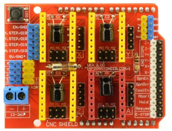
Note that this is a photo of version 3.00 of the CNC shield, which is the version I’m using (although mine does not have the glass fuse the photo shows). Due to changes made to grbl after this board was designed, specifically around PWM for spindle RPM/laser intensity control, not all the silkscreen legends labeling the pins are accurate. I have PWM control working, so will describe the connections I’m using to achieve that. If you have a later version of the shield make sure you find documentation appropriate to your version.
This photo doesn’t include the stepper driver boards. For my A4988’s I’m using 1/16 micro-stepping, so I’ve got jumpers installed on all 3 pairs of M0/M1/M2 pins under the drivers. I’m only using X, Y, and Z, so I only have drivers on the yellow headers.
With the exception of DC 19 V for the steppers, which comes in to the 2 screw terminals on the lower left corner of the photo, and the stepper motor connections themselves next to the driver headers, all my connections are made to the pins along the right edge of the board. I’ll list the pins that I’ve connected to and the purpose it serves. The white headers are the signal pins, all the black headers along the edge are ground connections. Also, the End Stops connections for each axis are in parallel - although they are marked + and - (for Max and Min) they are electronically identical.
SCL = probe connection (104 capacitor to ground for noise control)
SDA = M7 coolant relay signal. Switches 120 V AC on accessory outlet. I plan to use this for a vacuum hold down or other accessory.
5 V & GND = logic power to Arduino Nano VCC and GND and from there to relay board VCC and GND
RST = not used
Z+ = Spindle PWM connected to Arduino Nano PWM in, which controls PWM signal to triac board which in turn outputs variable AC voltage to spindle outlet. Originally the shield used this PWM-capable pin for the Z end stops as printed on the board. grbl versions .9 and later have swapped this pin’s mapping with SpnEn to allow spindle speed and laser intensity control via PWM. Some online documentation states this version of the shield is incompatible with later versions of grbl, but if you understand the pin change it works just fine. If you don’t have variable speed controllers this pin can easily be used for simple relay on/off via the M3/M5 commands.
Z- = second Spindle PWM - unused
Y+/Y- = Y end stop connection(s) (104 capacitor to ground for noise control)
X+/X- = X end stop connection(s) (104 capacitor to ground for noise control)
SpnEn = Z end stop connection
SpnDir = Normally used to control spindle direction but since my AC spindle isn’t reversible I’ve made a change as documented in the grbl firmware config.h file comments to use this as a separate Spindle Enable pin. This allows turning the spindle on and off without changing the RPM setting in the gcode command. May not be needed, but made sense to me as I was reading through the firmware comments and is working as expected.
CoolEn = M8 coolant relay. Switches 120V AC on accessory outlet, mostly for future possibilities since the relay pins were already mapped to gcode commands. Originally I was thinking to use this for an air blast for machining plastics or aluminum but I am now considering using “shop air” and a 12v air valve since I’ve installed a compressor and distribution lines in my shop. If I make this adjustment, I’ll just connect the signal to one of the currently unused relays on the board.
Abort = grbl Cycle Cancel button (mine’s red)
Hold = grbl Cycle Pause button (mine’s orange)
Resume = grbl Cycle Start button (mine’s green)
E-Stop = Unused in my configuration. This pin can be used to reset the Arduino board. I’ve chosen to wire my e-stop in the AC supply line so it kills all power to all elements of the system rather than just resetting the microprocessor.
You’ll note the phrase “104 capacitor to ground for noise control” used several times above. Since my end stop and probe lines run inside shielded cables right next to the motor wires, initially the end stops were unreliable as noise on their lines was interpreted as the switches being tripped. Adding small capacitors between the signal and ground lines for the end stops and probe connection completely solved this problem for me.
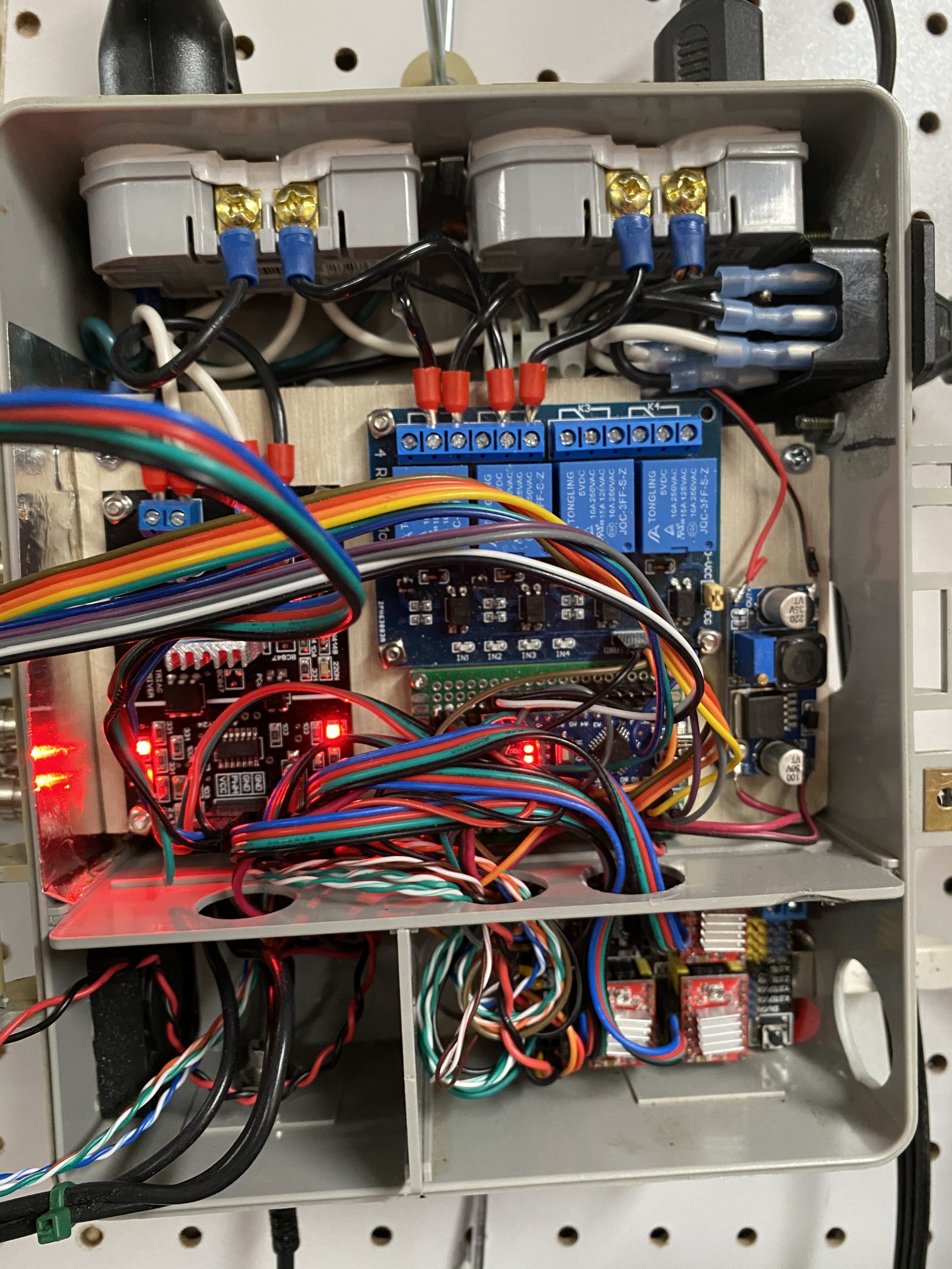
When wiring up the connections for all of these pins, I worried about getting connectors on the wrong pins while assembling or troubleshooting. Rather than having a whole bunch of 2-pin connectors to wrestle with in the tight space, I used 2x4 and 2x6 pin connector blocks that came in the header assortment I purchased a while back on Amazon similar to this. Now there are just 3 plugs to deal with, and I don’t worry about getting the connections out of order.
Let me know if you’re interested in more detail on the PWM control. It’s the one @vicious1 sells in the shop and is discussed in detail on a couple of other topics on the forums.
 I don’t think I’ve ever powered on the PSU on that without first having the PC powered on.
