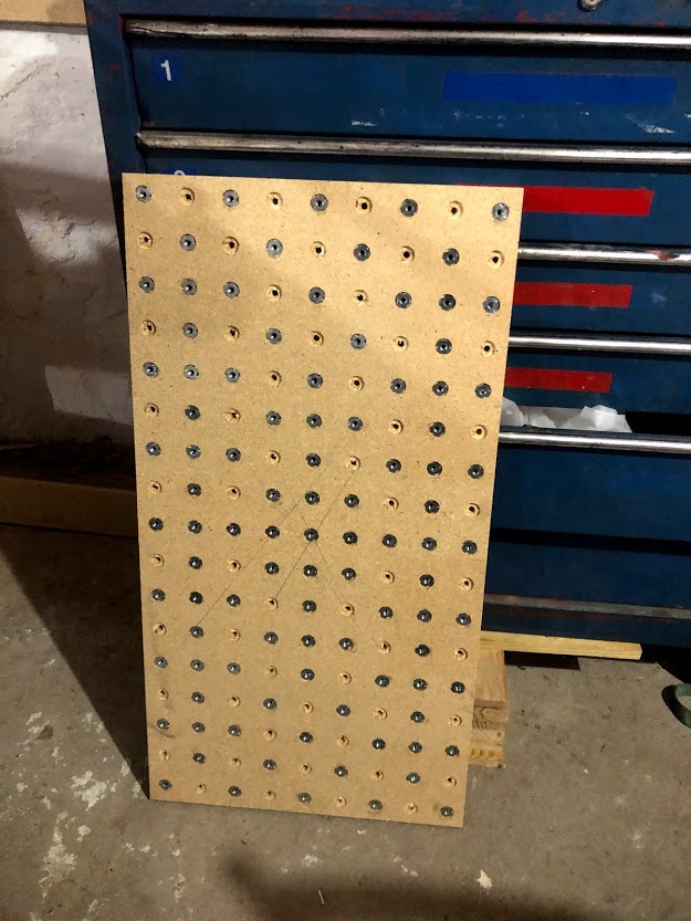
There are a number of possible solutions to this problem, and I’m going to suggest one approach. I’m going to assume you want to fix your current setup rather than start over, and that you drilled the holes for the inserts using your CNC. This suggestion comes in two parts. The first is a way to get your spoil board inserts better aligned to the machine. The second is to have the machine drill some holes with the spoil board mounted to use for pegs for stock alignment. The first part could be skipped.
To get your spoil board better aligned, author a cutting file that bores two holes a fraction of a mm deep. The holes should be just slightly larger than the bit you will have in the router for this test. The first hole will be at 0,0, and the second will be at 0 on the Y axis but the distance from the bottom left hole to the bottom right hole. So if your holes were 50mm apart, the second hole would be at 800,0 (16*50 = 800). Edit the .gcode file add a line at the bottom to pause…something like:
M0 Pausing now
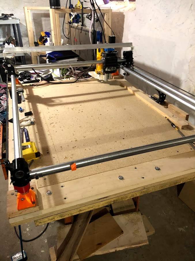
Next remove all the screws holding your spoil board down except one in a corner. Position the router over the center of the hole in the bottom left corner. With the router turned off, run the .gcode file. The end position when the router pauses should be over the rightmost bottom hole. If it is not, adjust your spoil board and repeat the process. You can lower the bit into holes before starting and at the end to get a better visual on how centered the bit is in the hole.
Once you are happy with the alignment, screw the board down and retest one last time. If you will be removing your spoil board for reasons other than replacement, I’d insert at least two holes through the spoil board into the base board for alignment pins.
Before calling this adjustment done, I’d author the same kind of cutting file on the Y axis. So if your holes are 50 mm apart, one hole at 0,0 and a second at 0,400, and test in the Y direction also. If the holes are correct one direction but off in another, you have a skew problem of some sort that needs to be addressed.
And Jeff makes an excellent point, creating hard stops to start with a the axes aligned is very beneficial.
This process will get your spoil board close, but I’d take it one step further and have the machine bore some holes specifically for the pegs. I’d bore these holes between the current holes. To start you just need a few on the X and a few on the Y. I’d would go with pegs 3/8" or larger, and I’d bore the holes all the way through the spoil board. Using larger pegs and deeper holes will mitigate any tilt that might occur when using the pegs. Since the machine will be boring the holes, you will be assured that the pegs in these holes will align your stock with the machine.
As noted above, you could ignore the first part of this suggestion about aligning the spoil board and simply author a row of peg holes in the X and Y. I only suggest the alignment because it makes other things work a bit better like creating rules to push your stock against, or having similar clamping across the stock.