The “public” parts of our house (foyer, living room, kitchen, etc.) were trimmed-out with nicer moldings than the “private” parts of the house (bedrooms, upstairs). We have some radius-top windows, and I’ve been wondering about using the LR3 to mill curved pieces to upgrade my trim, rather than buying either flex molding or hiring a millwork shop to create the radiuses.
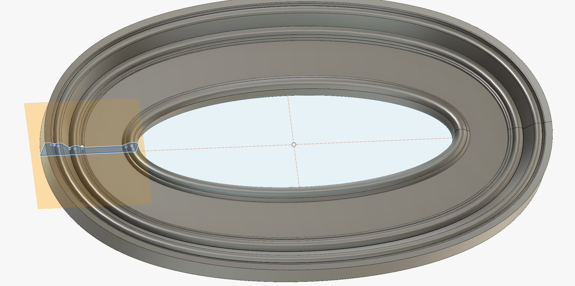
Along those lines, I also have a friend with a couple of elliptical windows that need casing, and for years we’ve talked about how to make those.
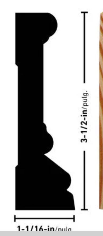
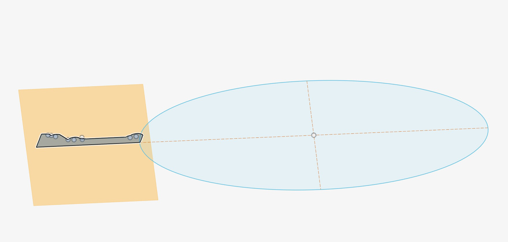
Last night I went online and searched “RB3 casing” or “Howe casing” which is the nicer profile in our house. Lots of sites have drawings of the end profile of their moldings, along with thickness & width dimensions. I grabbed a screenshot, imported as a canvas in Fusion360, and traced it out with straight lines and 3-point arcs. Once I had the profile, I created a little 6" extrusion of that shape.
I’m guessing I’d need at least 3 different bits to achieve such a profile. Even if I never actually create the carving, this was a fun exercise in modeling.
It really would! I’m probably getting way ahead of myself with this… the ONLY toolpath I’ve ever created was for my struts, and they’re not even installed yet. But if I can meander my way through this in Fusion, I think I’ll give the straight section a try on a chunk of 2x6, just leaving it kinda thick, working on the face profile.
If that works, then yeah, I’d love to give the full ellipse a try. Good to have goals, right?
The other thing that a real moulding factory would do is to glue up the stock in such a way that they minimize how much needs to be cut off. Only the thick edge would be thick, then possibly a thinner section and another somewhat thickened bit on the inner/nose edge. If I were trying to mill a large arch, I’d likely do it that way. For playing around, I’ll just generate the extra sawdust and start with flat stock.
Lol – thought about it? Yeah. Considered actually trying it? Hrrrmmm… probably not. It is fascinating how they used to – and sometimes still do – make such large and interesting moldings, rosettes, and other details. I’ve just recently seen videos of guys doing the same techniques with concrete stucco for the cornice of a building.
I do love me some nice mo(u)ldings, though. Used to subscribe to Fine Homebuilding for many years.
Usually I can get a close match by making pieces by routing some parts and fiddling with the table saw. The part in the first post would be five or so pieces for me! I used to keep tool steel strap so that I could make scratch stock to scrape the final profile to close enough to exact, and a lunatic mate of mine made plantation shutters for his entire house that way, all hand planed.
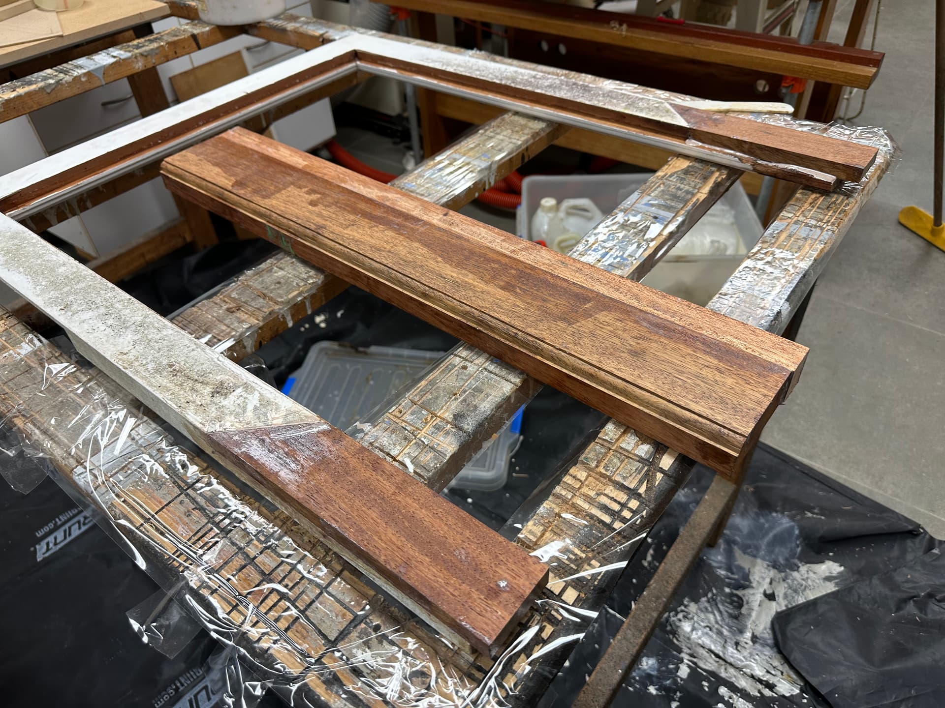
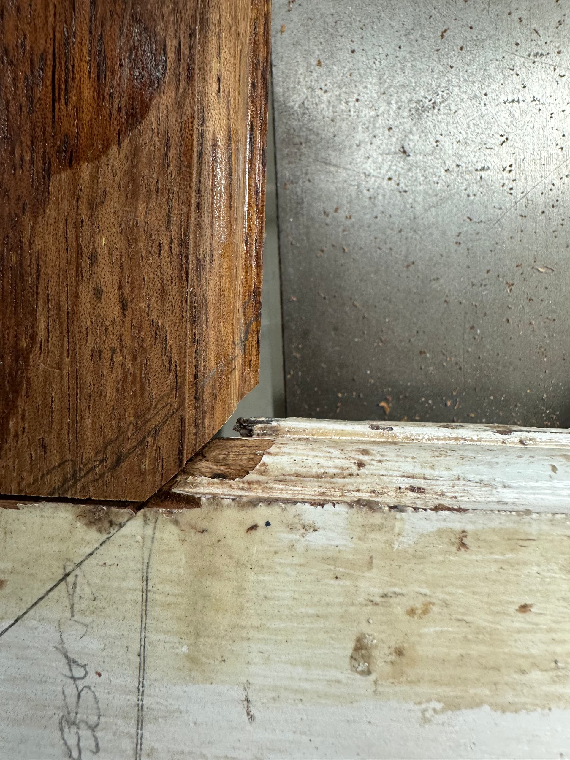
Here’s a simple project from a month or so ago - sorry no other pics than these early ones but you will have to believe me that the finished moulding was a perfect match and after priming the repair was invisible - just two saw cuts and a router to make the moulding, then a bit of hand scraping to tidy them. For the first time, I made a 3d printed male and female template so that I could gauge the exact profiles as I was going along and that worked really well.
The window was from a friend’s mother’s house - she insisted that she would be the best person to do the final painting, and at 102 years of age, how could we argue?
It may have been easier to make the whole frame from scratch, but it’s nice not to waste good timber so I cut out the rotten bottom rail, and half of the thickness of the bottom of each stile, made an approximate moulding shape (in the pics) assembled it with haunched bridle joints - mostly hand tools. It was a lot of fun, but it’s a long way from CNC stuff so I guess this is now off topic, but thanks for letting me share!
Yep, and he never rambles on for 2 minutes before saying ‘so let’s jump right in’; it’s all doing no talking.
This seems like it would be a good time to use the rigid insulation foam the docs mention for initial carving tests. You can experiment, cut relatively quickly without worrying about breaking bits while you work out what shapes you can do.
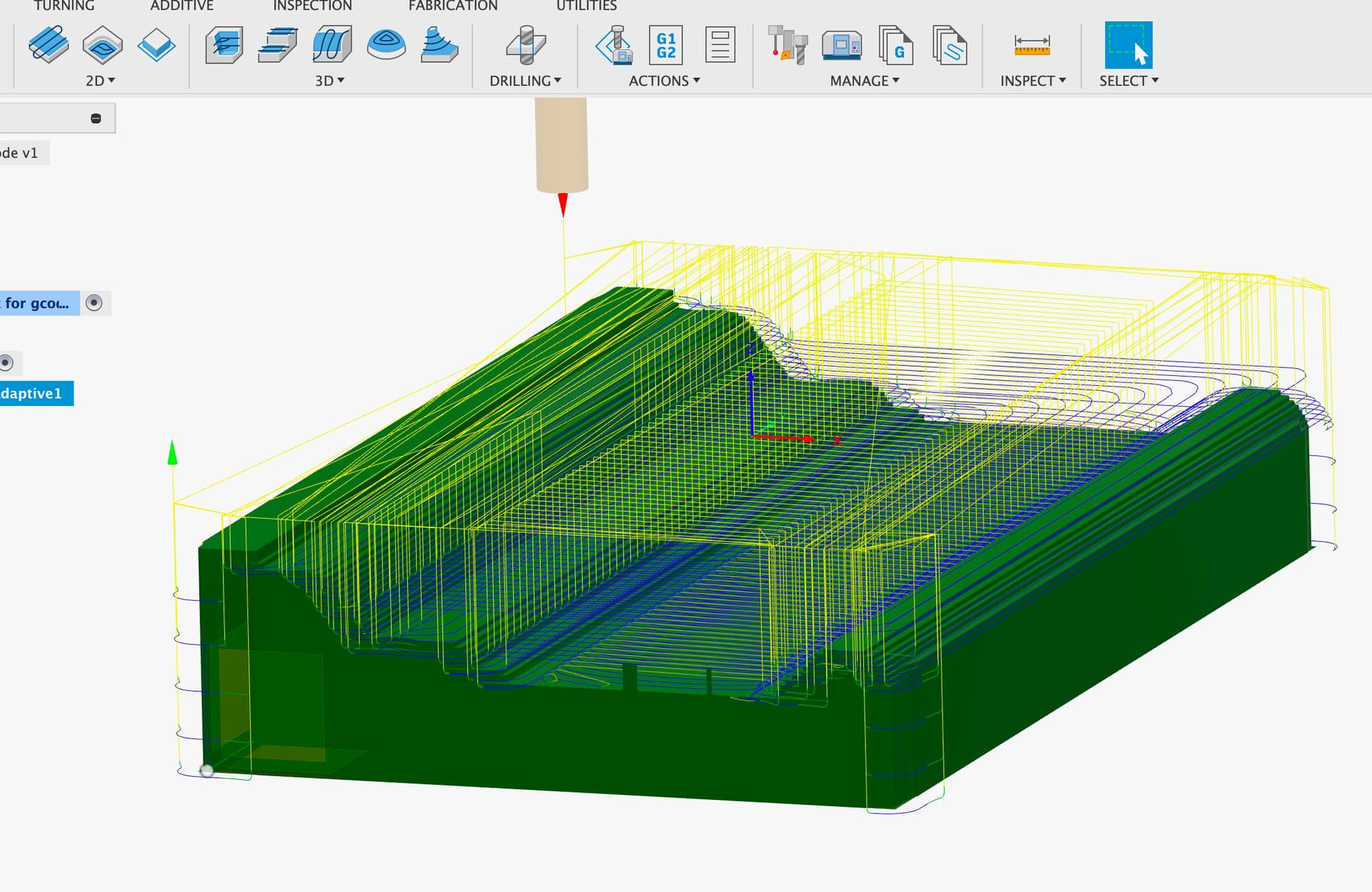
I was able to figure out how to create the toolpath in Fusion for the first bit, a 1/4" roughing bit. It’s also clear now how to create successive toolpaths for other bits, using the output of one as the input contour of the stock for the next tool.
I chose Adaptive Clearing(?) for this one, but I really don’t know which technique is best.
Here’s the result of the roughing bit toolpath in simulation. It’s still reporting a number of errors (like collisions) that I need to work out before I start spinning a physical bit, but it’s progress!
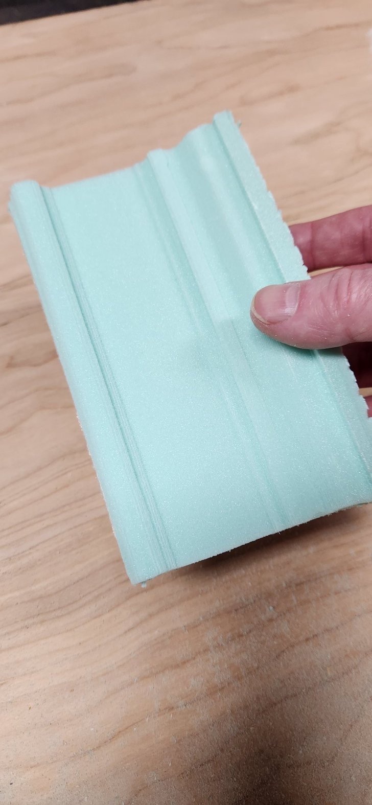
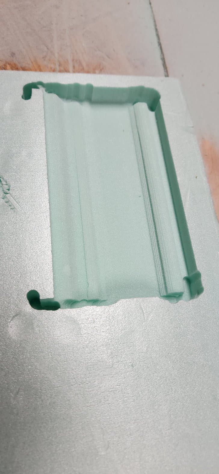
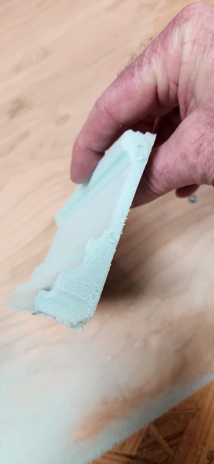
I taped down a piece of 1" rigid foam and gave my roughing pass a try. Gotta say, I’m thrilled with the results. My initial gcode was moving so slow that I bumped it up to 500% speed in the fluidd console, and this 6" piece then only took 15-20 minutes. I’ve really gotta work on my CAM settings, but the learning is what this is all about, right?
So for the results. I didn’t have an outline through-cut, so it just cut deep at the corners and did the roughing-out of all the interior space. When it finished, I used a razor knife to trim it down to the final outline.
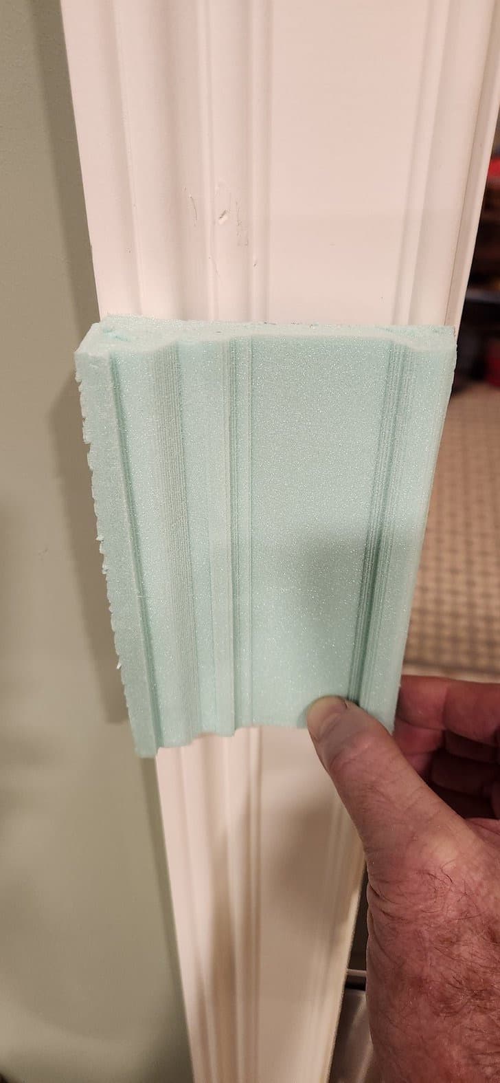
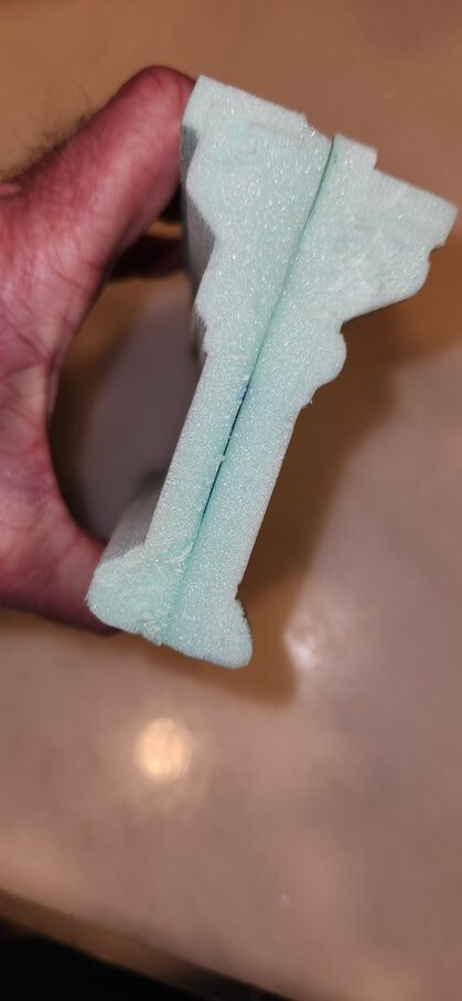
Tonight I added a second pass with 1/8" ballnose upcut and a third pass with 1/16" upcut. I could likely eliminate the 1/8" bit pass altogether. It really didn’t do a whole lot other than dig out the two valleys better. But then again, it can do it twice as fast as a 1/16", I guess.
I tried using my 30-degree V bit for the final toolpath, but Fusion was taking forever to generate it with the parameters I had set. If I could just use that to sharpen the valleys, that’s all I’d really care about. In the end, I decided that a 1/16" valley floor was good enough.
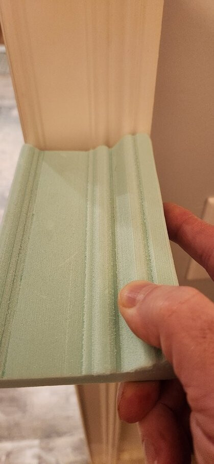
I’ve noticed that the RB3 casing in our house is a slightly different profile from the one I copied, but they’re very close anyway. As long as I’m not trying to butt or miter the two together, it would never be an issue.
(In the photos, remember that the outer edges were trimmed by hand off of the larger styrofoam sheet… ignore those irregularities!)
Yes, I’m really tempted to cut out the full ellipse from wood, but I also wonder how many more tests and refinements I ought to do first.
Examples:
Set up perimeter and interior outline cuts, probably with tabs
Test the full ellipse on foam board
Refine toolpaths for only 2 bits?
Play with feeds and speeds, stepovers, etc
I have a length of maple stair tread stock leftover from our old house. It’s 1 1/16" thick, but something softer might be a better choice as I’m still in the early learning stages.
I keep thinking I might be getting ahead of myself, and I probably am in some ways… but I discovered the LowRider five years ago during early Covid and started dreaming/scheming how to make it happen. Got my 3DP 3 years ago mainly to build the LR2, then shifted to the LR3 after printing a few LR2 parts because of the numerous improvements. Life put things on hold for a couple of years, but my brain has not stopped on this journey yet.
Here’s my current plan (subject to change): First, I need to “finish” the LR3 build. That means at least getting the struts installed. It might mean building a torsion table (4x8). What I have now is okay for doing narrow pieces along the Y axis, but going bigger should probably have a sturdier machine, especially if we’re doing Z profiles (carving), not just through-cuts like struts and torsion table parts.
As I write this, I’m printing the additional Y rail blocks needed for the full-length table. Right now I have about 5.5’ of Y range, hanging off the end of one side of the ping-pong table. Nonetheless, I’m really stoked about having been able to get a decent proof of concept even just in rigid foam, given the unfinished state of my machine and my early position in the hands-on learning curve.
You can do things “the way it is supposed to be done” if you are uncertain of what you want. Or you just dive in an try. Endmills might break, stuff will go wrong, but in the end it’s your journey, so to speak.
My third print on my Prusa mini after the Benchy and a Prusa sign was the Primo core. My first cut on the Primo were some tongues by Uncle Phil with a 6mm endmill, 3mm DOC, 2000mm/min, considered to be really fast back then and an aluminium touchplate. I just like to try and to probe. I haven’t done 3D milling though, mainly because of the time it takes, but if you have the time (like Shia’d say): just do it!