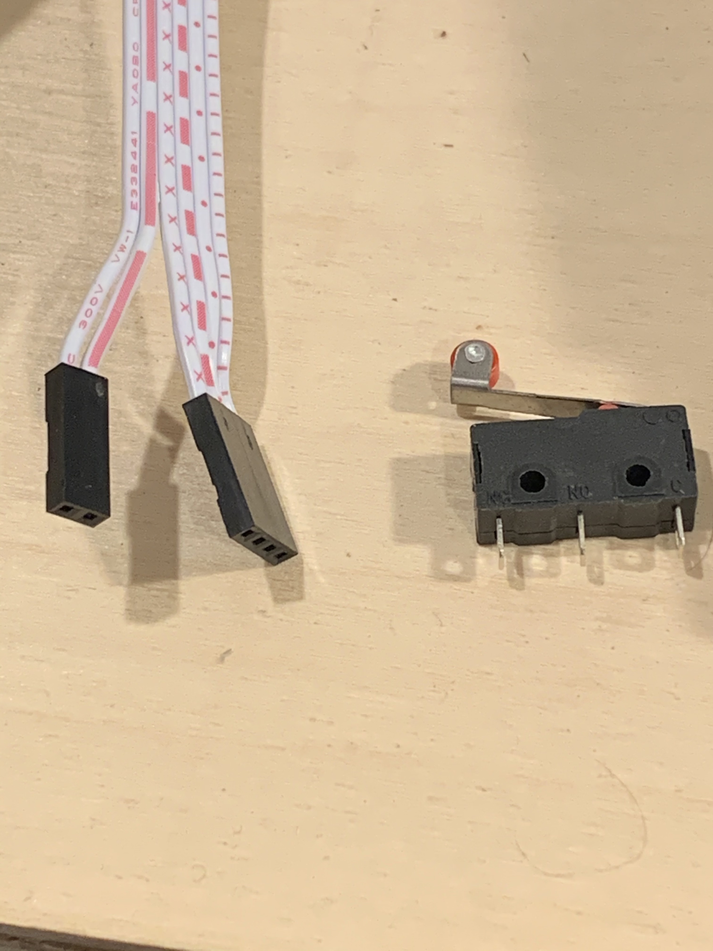
I bought the Dual-Switch harness from V1 as well as the switches. I’m in the process of wiring but am curious on any ideas of the harness pins to the switches? I made the mistake of showing the female end but I am sure the pin side is what I need to connect.
A few thoughts. First if your Steppers are similar to mine, you will have about 1 meter of stepper cable between the stepper and and connecting to the 4-pin male of cable you picture. So in terms of the switches it would easiest to patch in about 1 m of 2-connector wire between the switch and the male two pin connector you reference.
So the next question is whether you want a permanent connection or whether you want to be able to unplug the wiring. If permanent, you solder and then you are done. If you want to plug at either end of the 2-connnector 1m extension cable, then one end would be a female Dupont connection. I had these connectors from doing breadboard projects and just cut and soldered on a couple of female connectors on the end and then taped the connection to be sure it would remain secure. On the switch end, female spade connectors will fit on the switch pins. Note that I’ve had the spade connectors knocked off of the switches a coupe of times, but it was a quick fix.
Important: the firmware expects these switches to be wired normally closed (i.e. the wires connected when the switch is not tripped), so you might want to use a multi-meter to figure out the correct pins. For my switches, the pins were not the ones I expected. Also there is no polarity to the wires. And finally, if you are using a Rambo board, be very careful to read the pinout correctly when plugging the wires into the board.
Since you have the dual end stop cables, you probably already have the correct dual end stop firmware installed. If not, be aware that the serial versions of the firmware have the logic backwards (expect normally open switches) for some reason, so you need to update the firmware before doing any testing.
I don’t know where you are in the build process nor where you got your parts. If you purchased your SKR Pro board from Ryan, then you will have a correct firmware on the board. If you purchased your the dual ends stop wires at the same time, then you will have the correct firmware. There are two configuration for the MPCNC serial and dual end stop. Ryan flashes what he thinks you will need based on the parts you purchased. If you are unsure, you should be able to look at your display when booting the control board and see the version. The dual end stop version will have a ‘D’ after the firmware version number. If you don’t have a display installed, I believe sending a M115 will give you the info.
If you did not buy your board from Ryan, but did purchase all the specified other hardware, then you will need to 1) download the appropriate version of the firmware from V1, 2) potentially make some changes to support the drivers you purchased (if they are different than the ones Ryan sells), and 3) flash the firmware. This is the release point for V1 firmware. All the parameters in the firmware that V1 provides is setup to the hardware he specifies for the MPCNC.
If you purchased alternate hardware like a pully with a different number of teeth, or lead screw with few or more mm per revolution, you would need to modify a few parameters in the firmware. These modifications can be done directly in the firmware or done after you your rig is running through g-code. Based on the information on this form, needing to make this kind of change is exceeding rare.
As for testing the end stop logic before you’ve installed the end stops, as mentioned above, the dual end stop firmware expects the connection to be normally closed. So if you have some Dupont cables, you could jumper between the signal pin and ground for all your end stop connections. Then start your homing sequence. Pulling the jumper off will stop that stepper. If you are having trouble, an M119 g-code can give you the states of all the end stop switches.
Edit: Also if you are having to modify firmware anyway, consider modifying the following section in your configuration.h to match the size (in mm) of your XY working area.
// The size of the print bed
#define X_BED_SIZE 200
#define Y_BED_SIZE 200
Terminal markings:
C = Common
NC= Normally closed
NO = Normally open
One wire always goes to Common. Choose the other wire based on the desired behavior. Normally open means the circuit is not connected until the switch lever is pressed. Normally closed means that pressing the switch lever breaks (opens) the circuit.
As noted above, it seems that C and NC are the terminals you should use.
Historically, when using endstop switches for safety (we’re only using them for squaring the machine), you want them NC, so if there’s a wiring failure (much more common than a switch fusing short), it fails “safe”. It really doesn’t matter from a technical standpoint, except that the default is NC. You’d have to tweak the firmware (or issue the appropriate command) to switch to NO operations. Again, we aren’t using them for safety or for the protection of the machine, just for squaring and auto-homing.
Thank you for the very complete response. Went to bed depressed yesterday as I just hit the electronic brick wall as well as all the sad stuff in the news.
Saw your reply and thought “here is some great info to try tomorrow…”
I am going to check everything per your advice. I also want to try to maybe flash the non-switch version just to please get a grunt out of a motor.
Thank you Tom and Wade. That was one area I felt okay on and I think I show my age by calling them “micro-switches” as the trade name we used as a kid (I’m 65) I still call the tab and receptacle as “Sta-Conn’s”
Ironically I spent my career designing connects for Molex and was pleased at Micro-Center Computer they referred to the 4-pin as a “Molex” connector.
Now here I am not able to get a silly stepper motor to respond…
Just so you don’t jump down a rabbit hole, end stops are only used if you are homing the machine. If you are attempting to move the motors any other way like from the display or Repetier-Host, or running g-code, the end stop switches have zero impact. The #1 reason I see motors not running on this forum is that they are not getting power. Some boards (the Rambo included) require power to be wired to both the steppers and to the control interface. If it is not a power issue, and you are stumped, then I’d open a new topic. Include info on 1) the board, 2) the drivers, 3) power supply, 4) what firmware you are using and 5) a picture of your board wired up. Usually someone can almost immediately spot the problem.