Yes, I have a 25mm LR2.
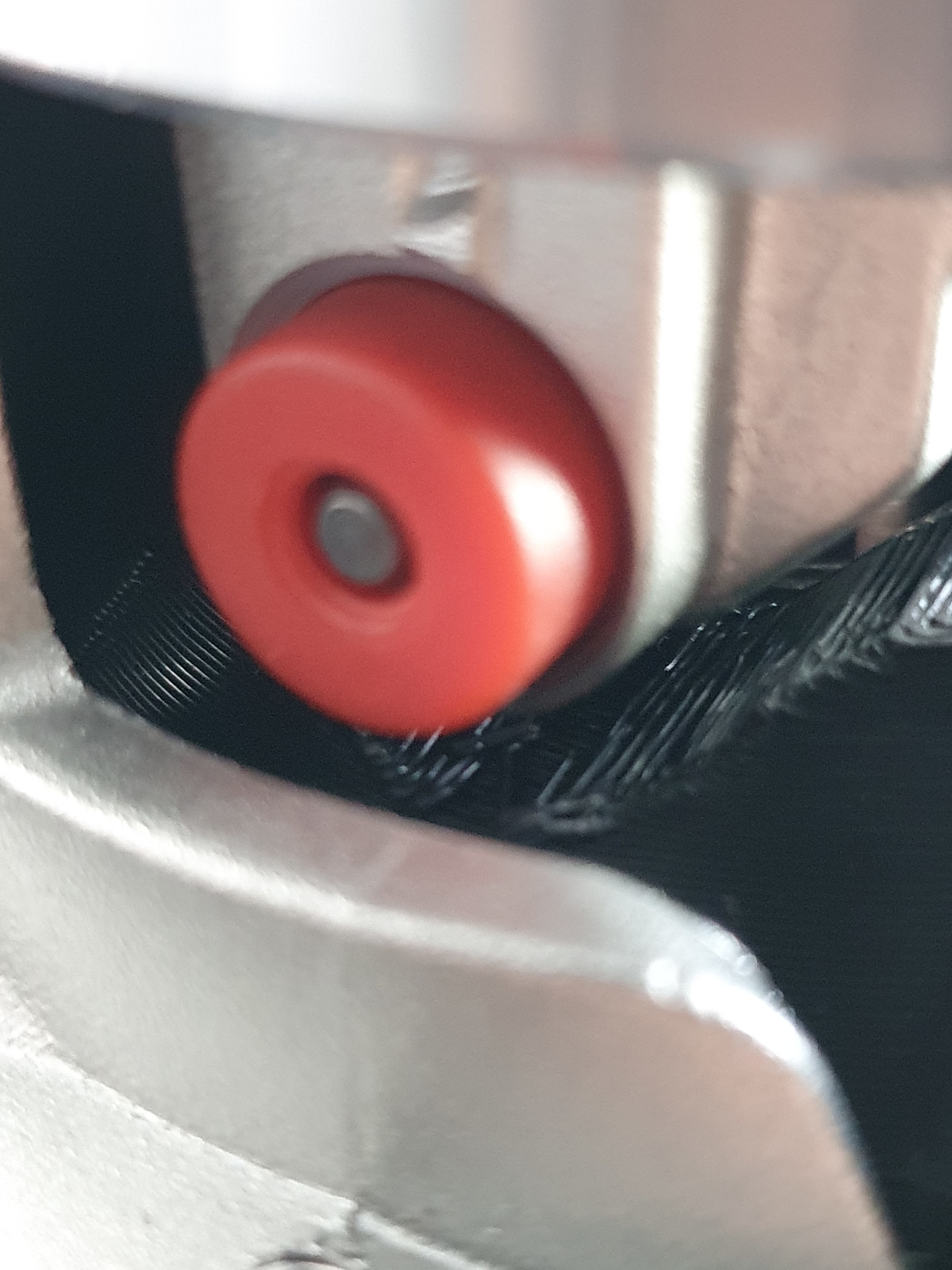
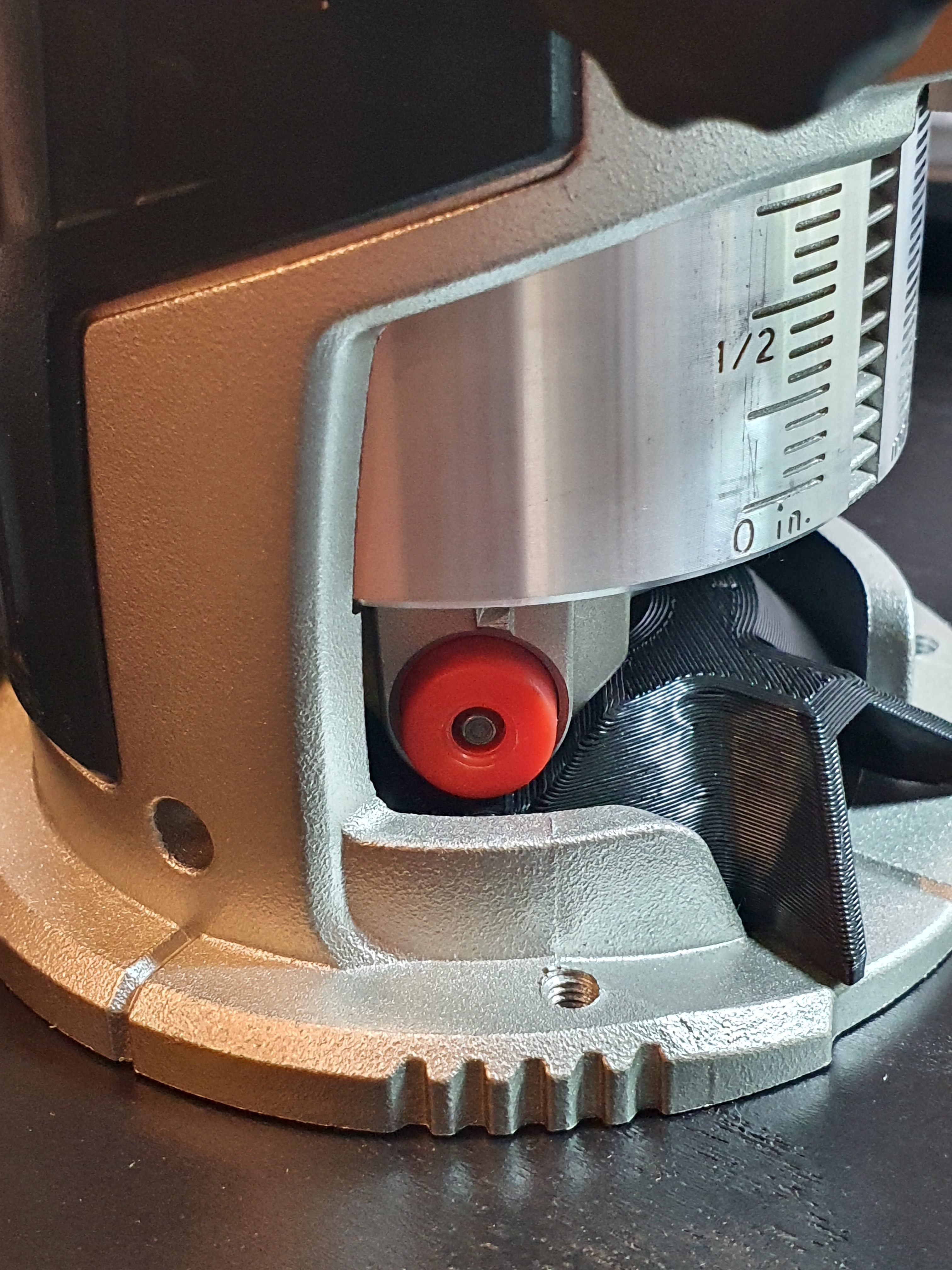
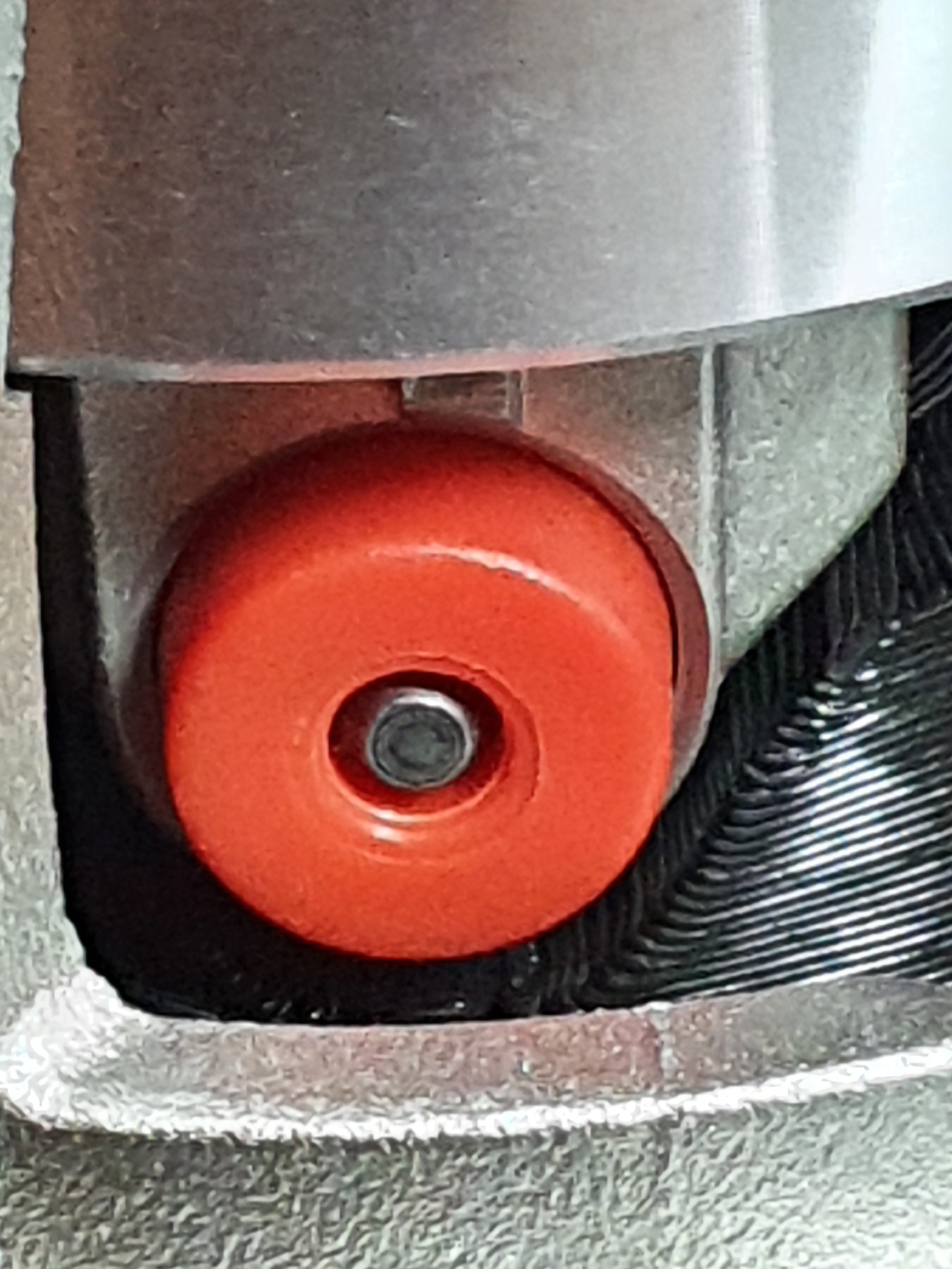
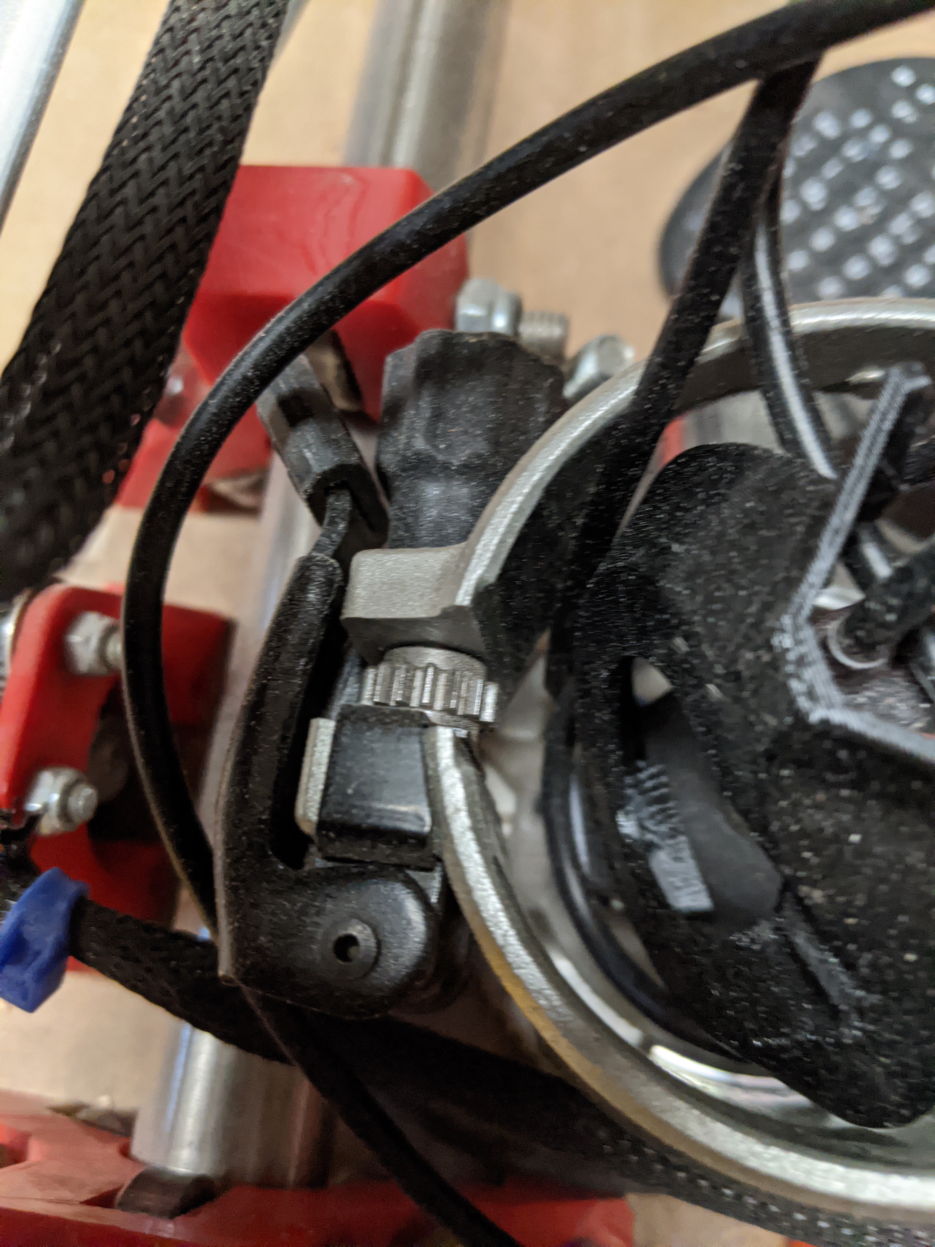
I’ve just tested the fit on my Makita RT07000C: In my case too the red push-button “bulge” is not well aligned to the recess in the VacDuct part. There is approx. 2.5mm clockwise difference on the verticals from the center of the button to the center of the recess in the printed part. @frederik: would it be possible to publish a version where the recess is rotated more towards the back? My CAD skils are not up to this task 
The fit of the VacShoeTop is close to perfect. My printer didn’t produce crisp corners for the 2 small locating tabs and I had to file the corners a tiny bit but otherwise no issue!
I ran into a similar problem with a power.supply case and switch I used my dremel and a sanding drum then by hand and file not a elegant fix but serviceable
@charliefd Would you mind trying the attached file instead?VacDuct Makita rotated.stl.zip (242.3 KB)
1 Like
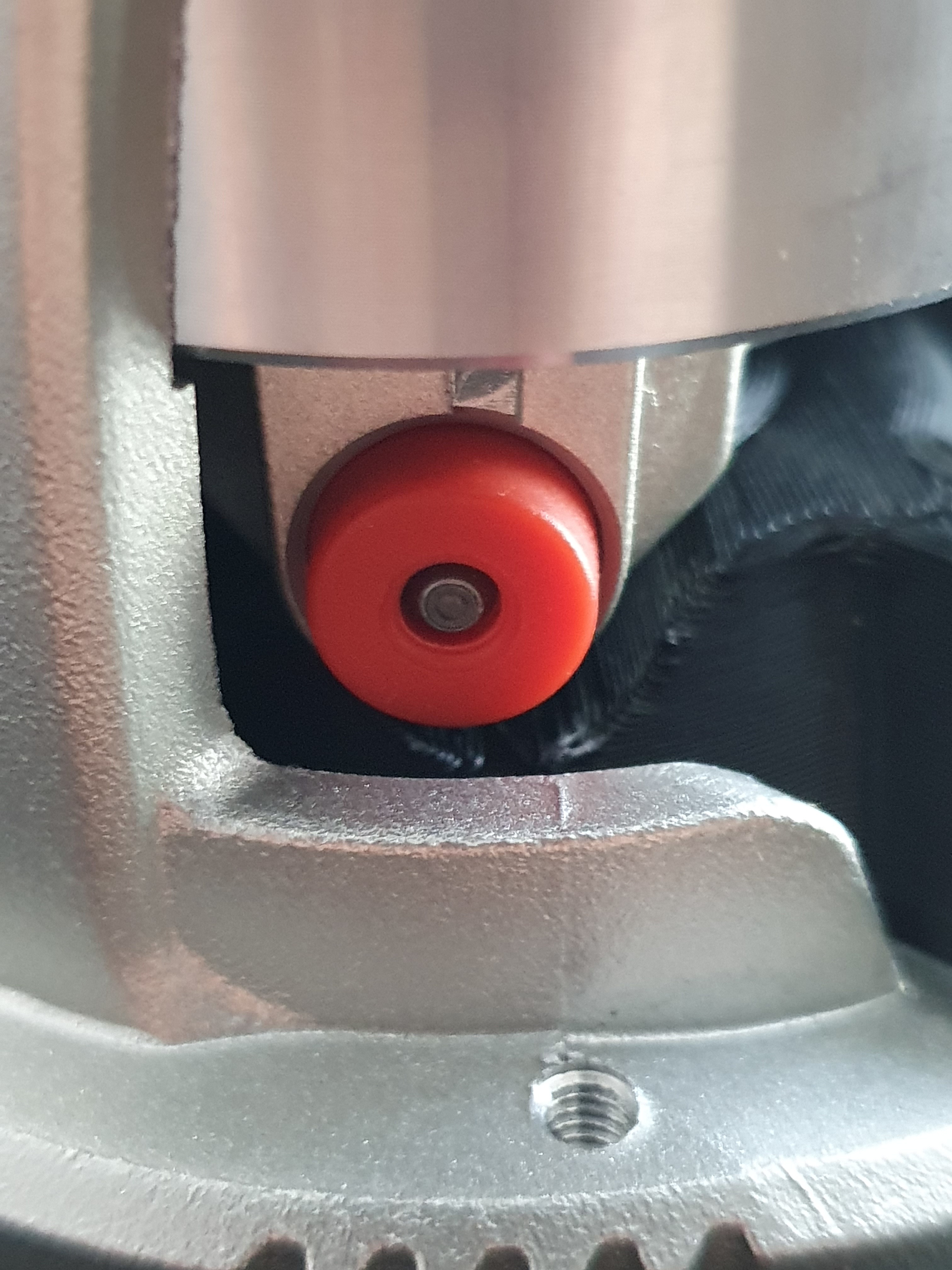
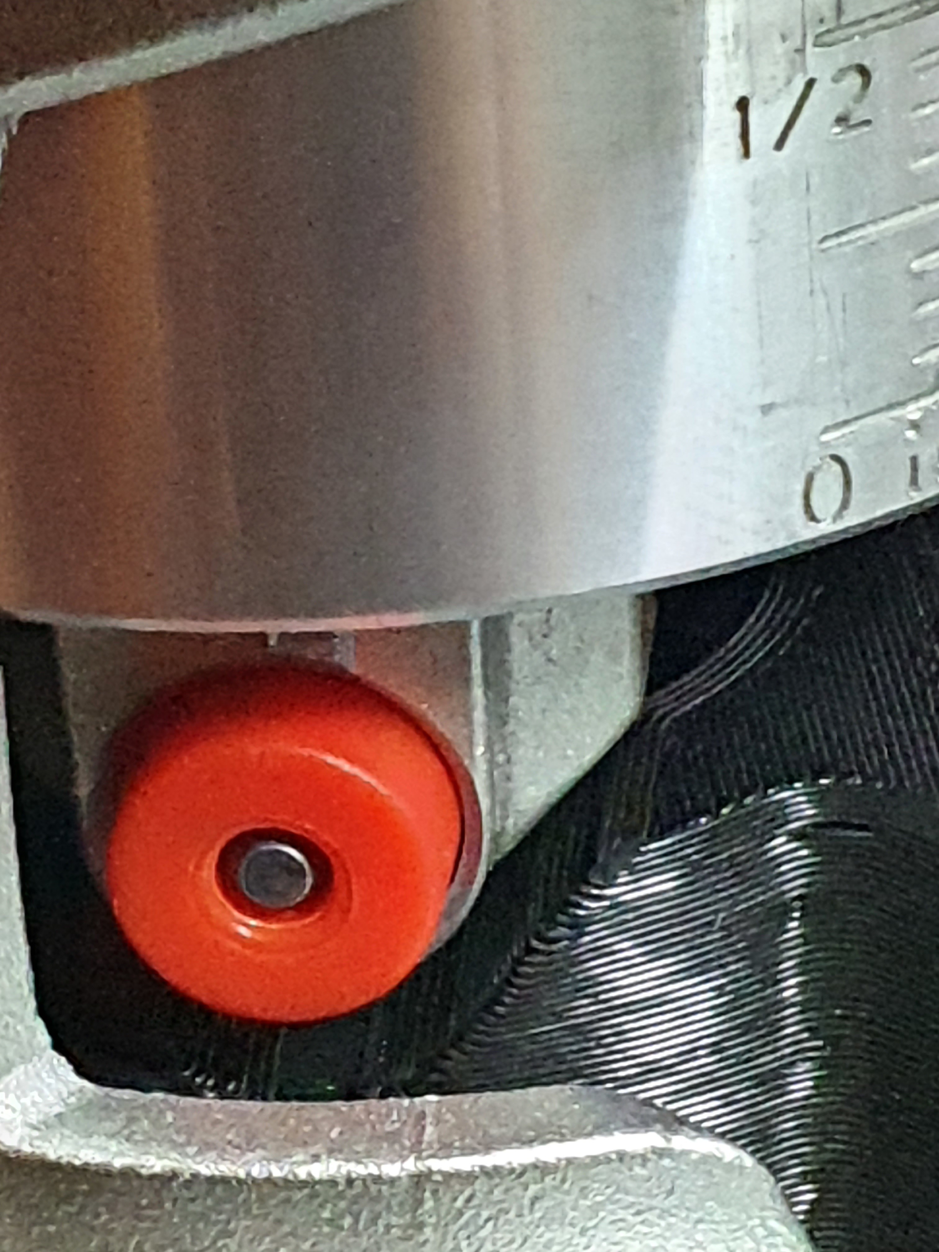
@Frederik: it is now centered! Thank you!
A perfectionist would say that the recess could be slightly wider to match the slope of the router protrusion: the angled sides of the “bulge” hit the top corners of the recess before the rounded part touches the bottom. But I’m quite happy with it  , in fact I clamped the router a bit higher so there is no touching involved
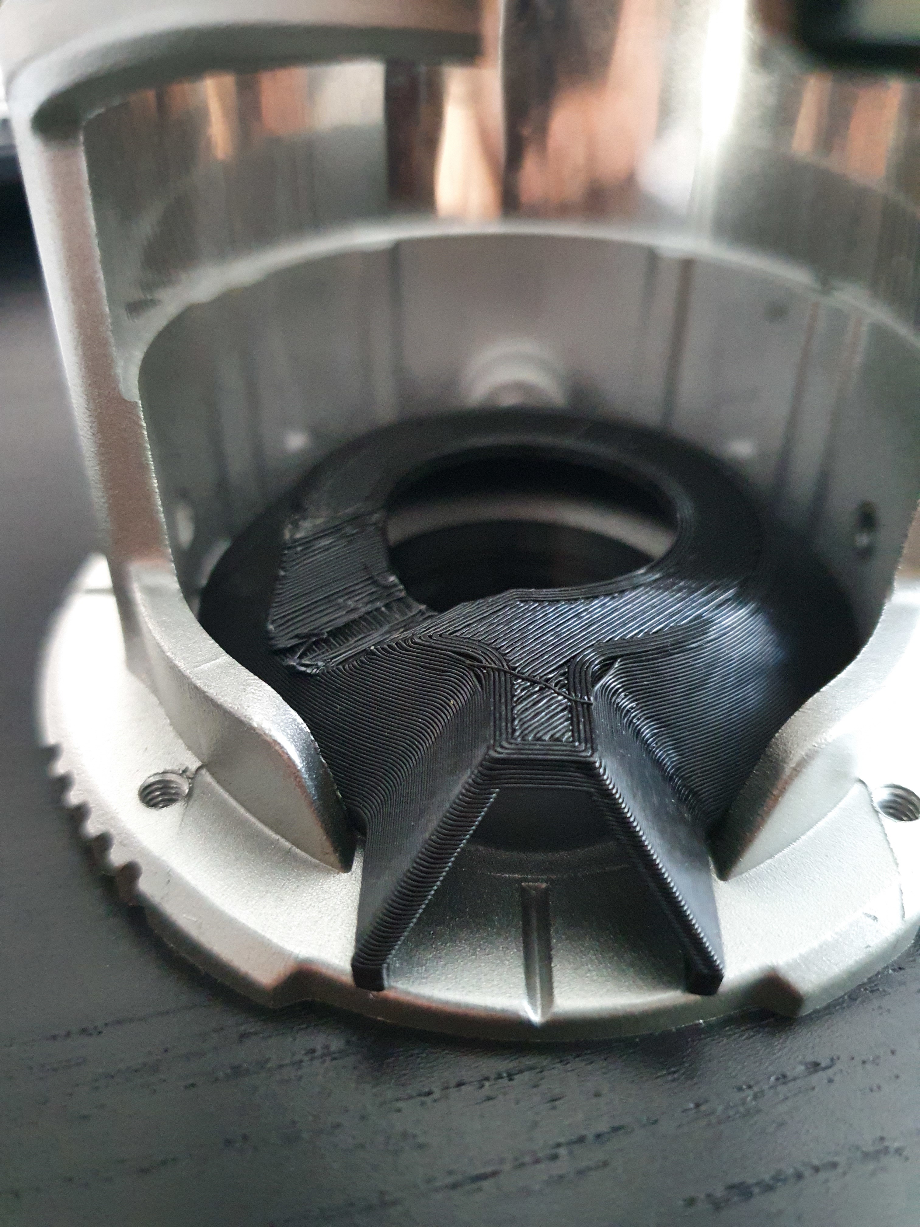
Symmetric and beautiful:
Touching top corners:
Raised a milimeter or so:
Luckily changing that is quite easy with parametric CAD. I wonder why I didn’t notice this - maybe they changed the design of the router a bit.
Anyways I’ve attached a version with wider chamfers that should fix this problem.VacDuct Makita wider dent.stl.zip (242.1 KB)
Wanted to upload this to Thingiverse, but it’s throwing errors (again).
2 Likes
@frederik I’ve just finished printing this new part, dry fitted on my Katsu (Makita clone) and everything fits great…redoing the base plate…so testing will have to wait a few more hours… 
One question what are the hose brackets for?
Thanks for sharing your work.
Àlex
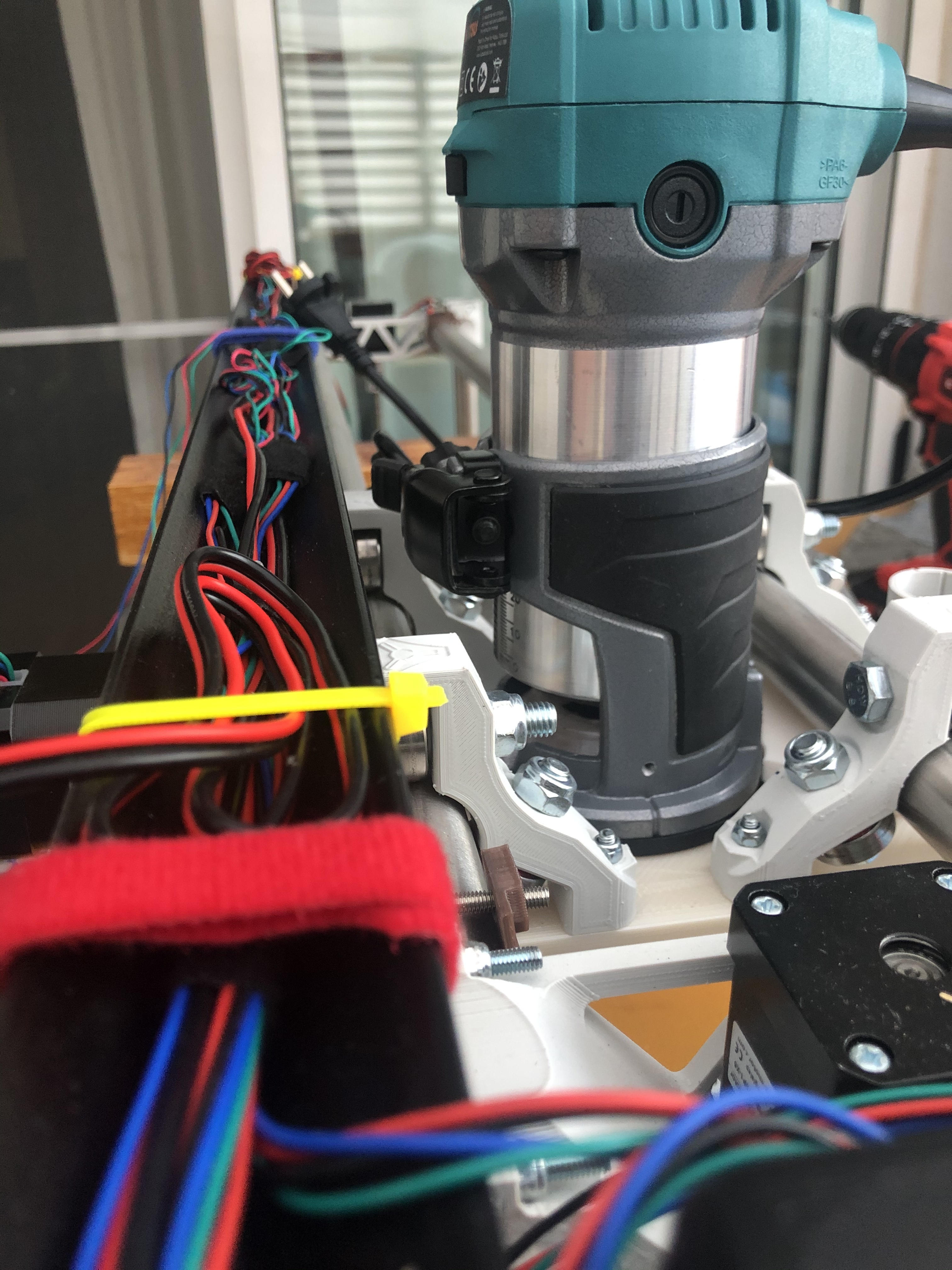
The router base’s clamp is hitting the vacuum hose bar. There are two options:
- use these provided hose brackets which are high enough to clear the clamp
- flip the clamp on the Router’s base itself to open the other way
1 Like

Parametric CAD sounds great. What software have you used for this part? OpenSCAD by any chance?
The part is perfect for my Makita RT0700C. There must have been some hardware revision at some point that made it a bit different than yours.
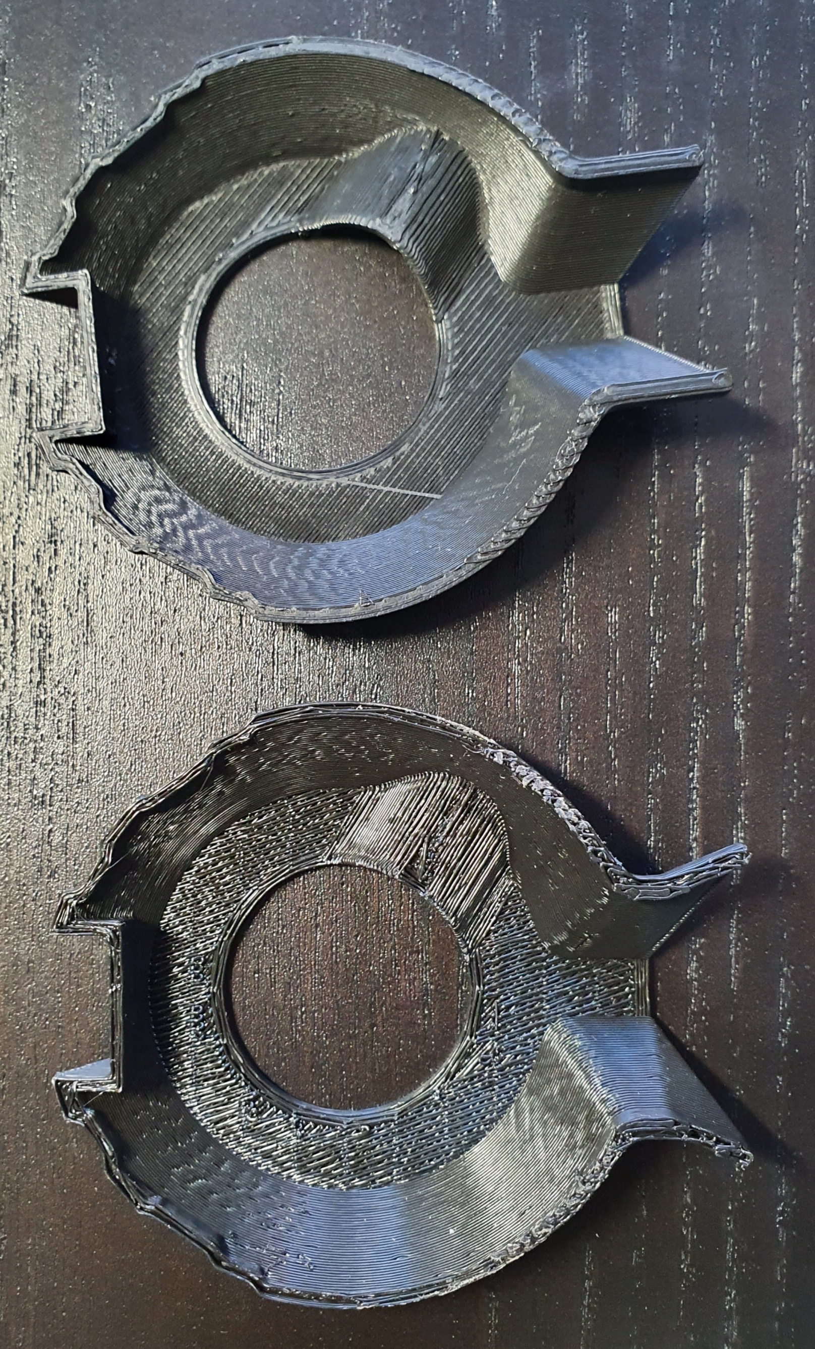
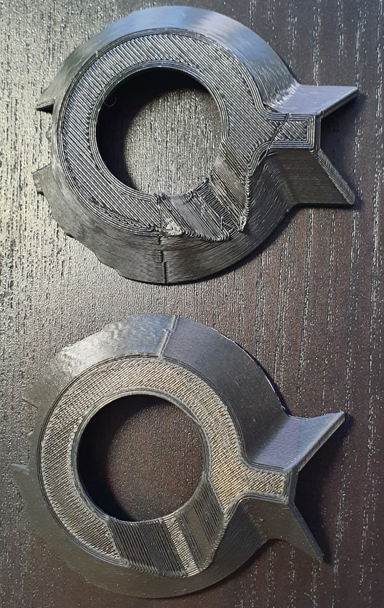
How do you guys print the VacDuct part? I’ve always rotated the part and printed from the small diameter face up with no supports and seems to be OK(ish): even if it has some sagging of the sides it takes just a moderate push to fit and lock in the router base. Is there some (other) advantage of printing the part in the original orientation and if so what kind and density of supports are advisable?
L.E.: printing the latest version again in original orientation with “grid” support at 15% to compare
L.L.E.: the part looks marginally better on the outside - worse on the inside flat and around the brim where the support had to come off. Fits just as well from what I can tell. My little experiment shows it is easier to print this upside-down and it might even fit slightly better (no chance for the corners to lift from the plate as it appears to have happened just a little bit in my print)
@charliefd I printed mine with the small side down, touching the bed, no supports and at 50 mm/s print speed and 100mm/s travel, infill can’t remember, but on the LR2 I tend to go for 4 perimeters and infills of 50-60% in most parts and this one came out good enough to fit very nicely inside the Katsu enclosure.
The small pin on one side fits very nicely in the bolt hole and the router seats so tightly on it that won’t go anywhere !!!
I wouldn’t bother going through the hassle of supports…hope it helped you.
Àlex
1 Like
I designed the part to be printed upside down without supports. I do get some minor sagging in the “divot”, but nothing that should affect functionality.
Hello, sorry but I dont understand,
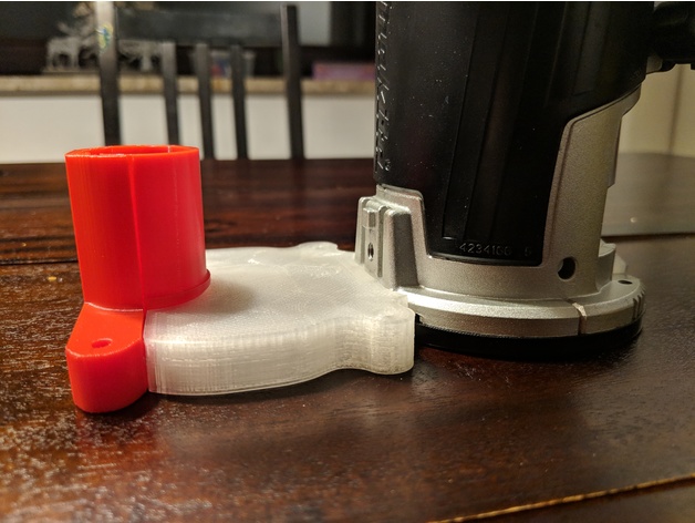
How did you put the bracket backwards? Considering that the vacduct have to be in that position to redirects the router’s exhaust air away from the intake of the vacuum shoe.
Sorry but Im from Argentina and my english isnt so good. Maybe you can explain me in more detail.
You unscrew the nylock nut and remove the bolt, then you can take off the clamp, flip it and put it back together:
Can anyone convert the dxf flat part file to a pdf for me? Something that I can print out as a full sized template?
Thanks,
Jerry
In this topic, I attached a ZIP file containing PDF versions. I don’t know if it matters, but the DXF files used in the conversion were pulled from the 25.4 version of the LoweRider.
Here is a PDF of the plate. Full disclosure that my CAD software can’t export PDF, so I used a web converter. Unfortunately that messes up the scaling. You need to find the right print scaling to make sure that the part is exactly 230mmx140mm.
Makita_RT0700C_Plate.pdf.zip (9.5 KB)
what about the vac tube at vac the next to the white one. will ryans work on it?
this is the one from this but the red piece is not in the zip file the white part is. does the one that comes with the lowriders on ryans plastic parts work with this.
Yes, all the other parts are Ryan’s, you only need the one printed part different.
I also removed the black part at the router base