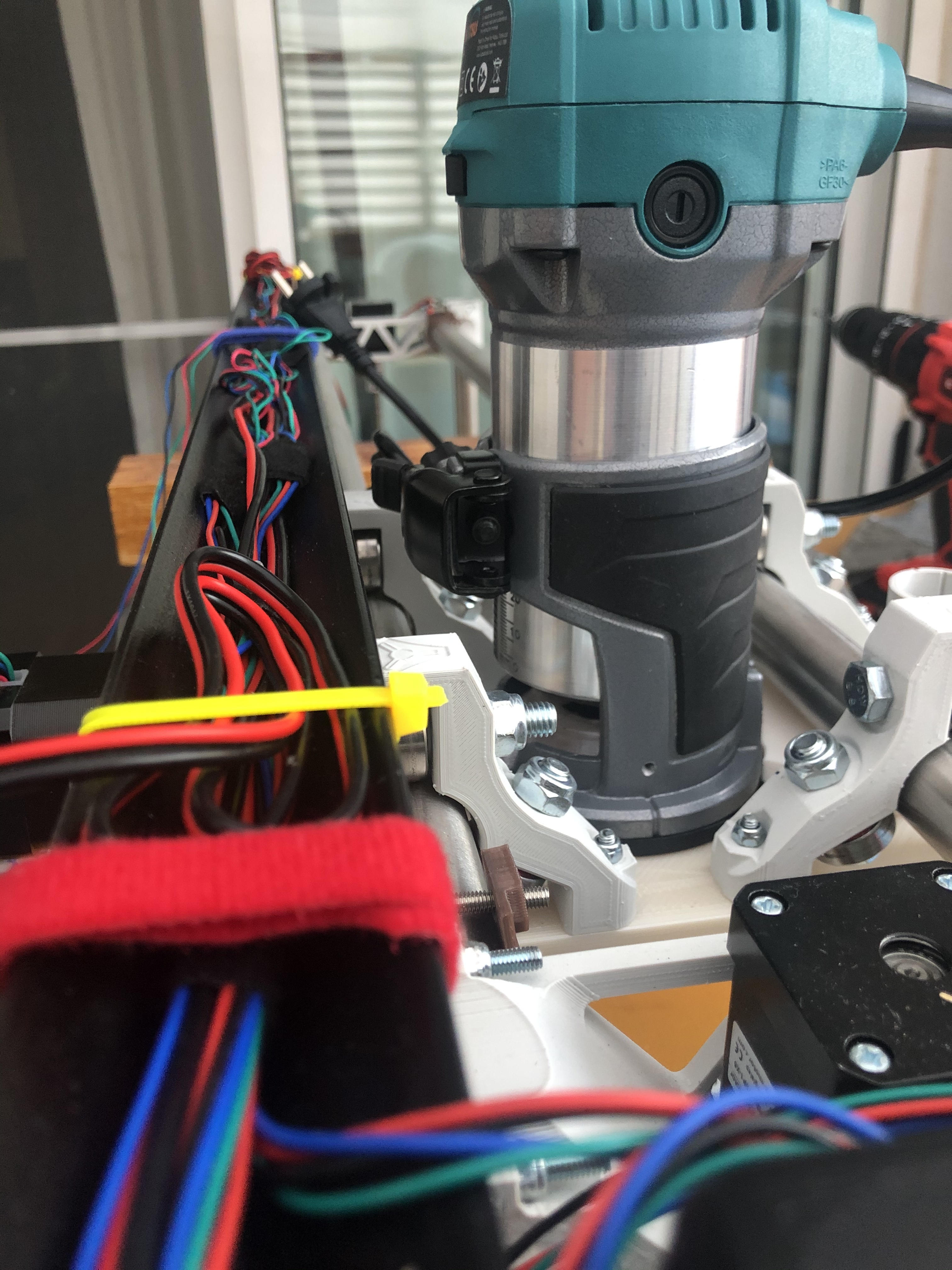
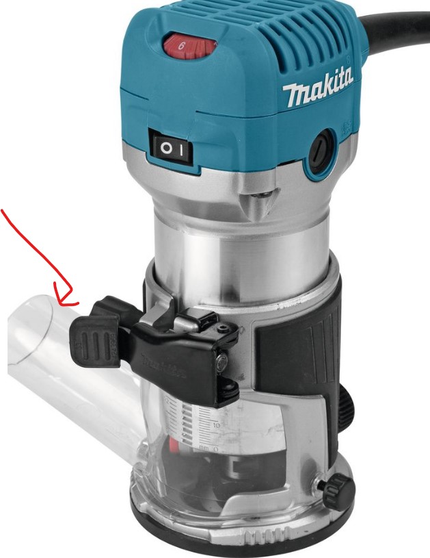
The router base’s clamp is hitting the vacuum hose bar. There are two options:
- use these provided hose brackets which are high enough to clear the clamp
- flip the clamp on the Router’s base itself to open the other way
The router base’s clamp is hitting the vacuum hose bar. There are two options:
Parametric CAD sounds great. What software have you used for this part? OpenSCAD by any chance?
The part is perfect for my Makita RT0700C. There must have been some hardware revision at some point that made it a bit different than yours.
How do you guys print the VacDuct part? I’ve always rotated the part and printed from the small diameter face up with no supports and seems to be OK(ish): even if it has some sagging of the sides it takes just a moderate push to fit and lock in the router base. Is there some (other) advantage of printing the part in the original orientation and if so what kind and density of supports are advisable?
L.E.: printing the latest version again in original orientation with “grid” support at 15% to compare
L.L.E.: the part looks marginally better on the outside - worse on the inside flat and around the brim where the support had to come off. Fits just as well from what I can tell. My little experiment shows it is easier to print this upside-down and it might even fit slightly better (no chance for the corners to lift from the plate as it appears to have happened just a little bit in my print)
@charliefd I printed mine with the small side down, touching the bed, no supports and at 50 mm/s print speed and 100mm/s travel, infill can’t remember, but on the LR2 I tend to go for 4 perimeters and infills of 50-60% in most parts and this one came out good enough to fit very nicely inside the Katsu enclosure.
The small pin on one side fits very nicely in the bolt hole and the router seats so tightly on it that won’t go anywhere !!!
I wouldn’t bother going through the hassle of supports…hope it helped you.
Àlex
I designed the part to be printed upside down without supports. I do get some minor sagging in the “divot”, but nothing that should affect functionality.
Hello, sorry but I dont understand,
How did you put the bracket backwards? Considering that the vacduct have to be in that position to redirects the router’s exhaust air away from the intake of the vacuum shoe.
Sorry but Im from Argentina and my english isnt so good. Maybe you can explain me in more detail.
You unscrew the nylock nut and remove the bolt, then you can take off the clamp, flip it and put it back together:
Can anyone convert the dxf flat part file to a pdf for me? Something that I can print out as a full sized template?
Thanks,
Jerry
In this topic, I attached a ZIP file containing PDF versions. I don’t know if it matters, but the DXF files used in the conversion were pulled from the 25.4 version of the LoweRider.
Here is a PDF of the plate. Full disclosure that my CAD software can’t export PDF, so I used a web converter. Unfortunately that messes up the scaling. You need to find the right print scaling to make sure that the part is exactly 230mmx140mm.
Makita_RT0700C_Plate.pdf.zip (9.5 KB)
what about the vac tube at vac the next to the white one. will ryans work on it?
this is the one from this but the red piece is not in the zip file the white part is. does the one that comes with the lowriders on ryans plastic parts work with this.
Yes, all the other parts are Ryan’s, you only need the one printed part different.
I also removed the black part at the router base
thanks dan
Hey Guys,
I just got back into completing my build again (Life keeps getting in the way haha). I have the Makita RT0700CX as its the only easily available one in Aus. It seems to fit/match up exactly to the 0700C and 0701C.
I had a slight misalignment of the VacDuct, this could be a slight inconsistency between the models, that was an easy fix, and that part is perfect, thanks,
I was hoping the brains trust here could answer one thing for me though. The clamp hitting the track for the vac hose etc, is there a specific reason why it has to face this way. It seems to me, that a 90* rotation anticlockwise, would give me easier access to the speed controller and switch, as well as giving plenty of access for the clamp. I was going to modify the VacShoe top part, in order to accommodate this orientation, but I am guessing there was a reason this wasn’t done? Or was it just to match with the DeWalt orientation?
Thanks Guys.
If you scroll up in this thread you’ll see that flipping the clamp is exactly what people have been doing.
Sorry, I might have made that a bit confusing. What I want to know, is if rotating the the entire shroud 90* counter clockwise, would present any issues in the way the machine works. Not just the clamp.
Kirt
Oh, my bad. If it fits I’d say it’s worth a try. I would worry that the structural integrity of the plate would suffer since the cutout would leave less “meat” in the middle of the plate.
Potentially the plate could also be more impacted by drag from the vacuum hose and could tilt side to side since the lever is bigger.
So, I think we’re getting our wires crossed haha.
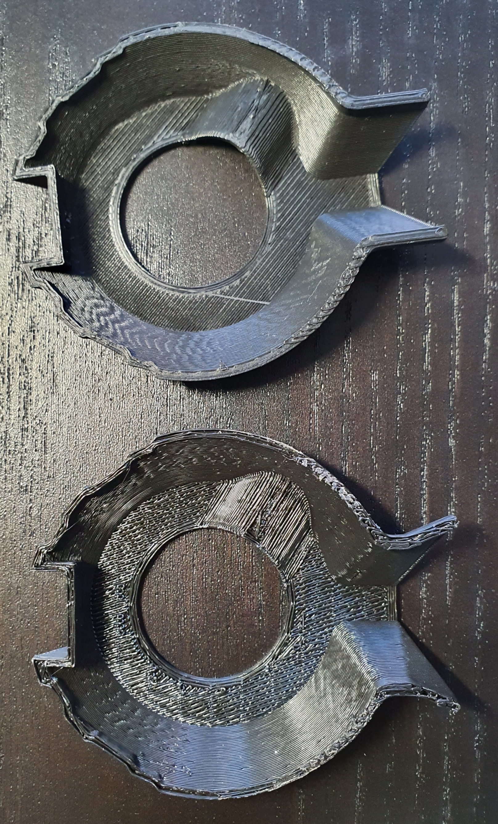
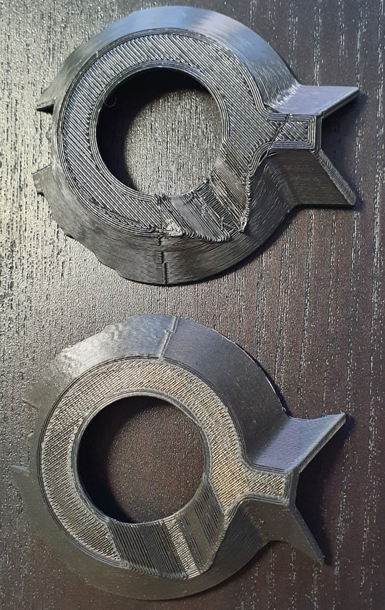
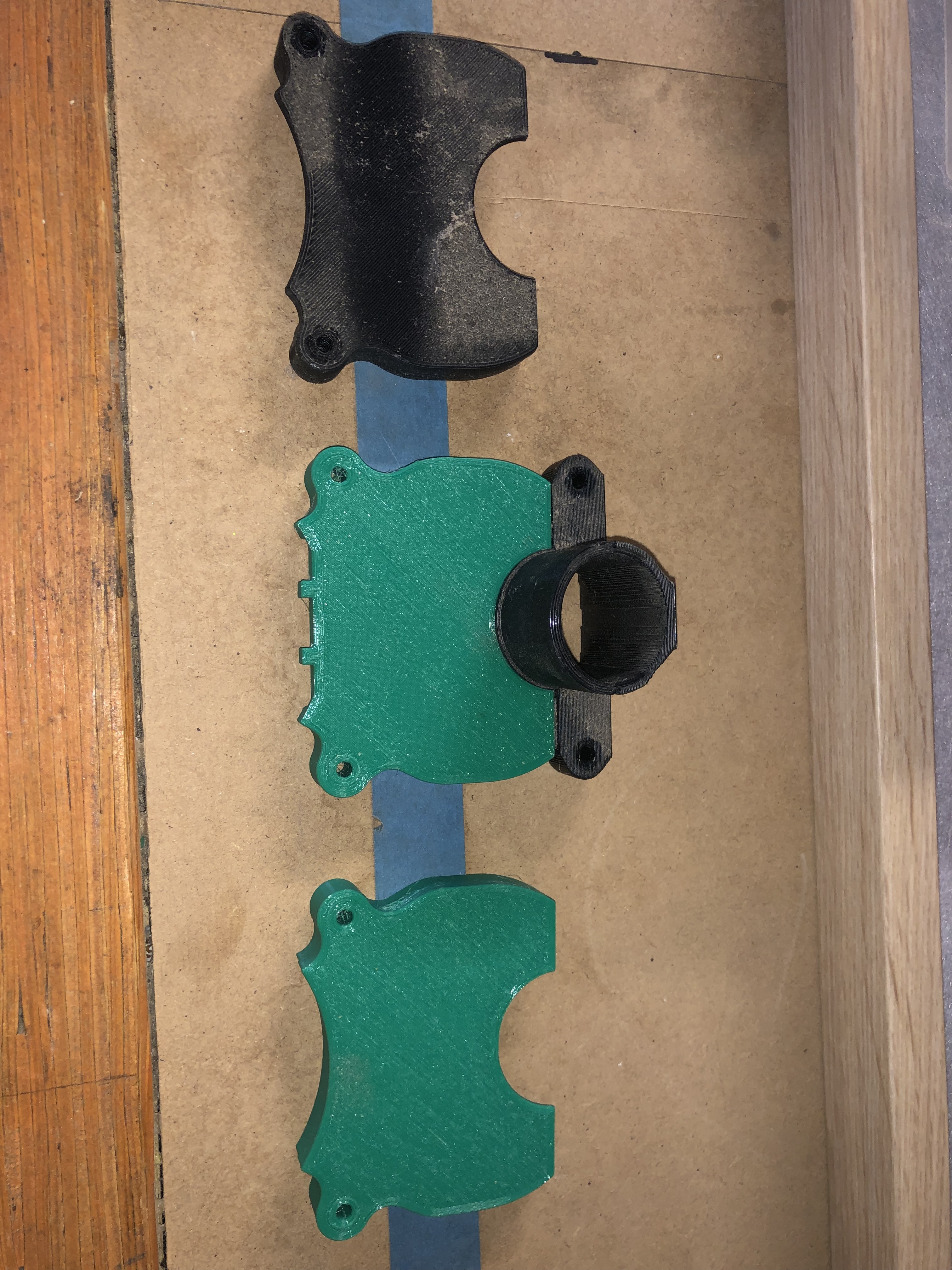
So I decided to just replicate the part so it’ll fit the way I want, so I can show you an example to better explain it. Hopefully this makes more sense, I’m not great at explaining haha.
So, top one is the original part, centre is the modified part from thingiverse, and bottom is my part.
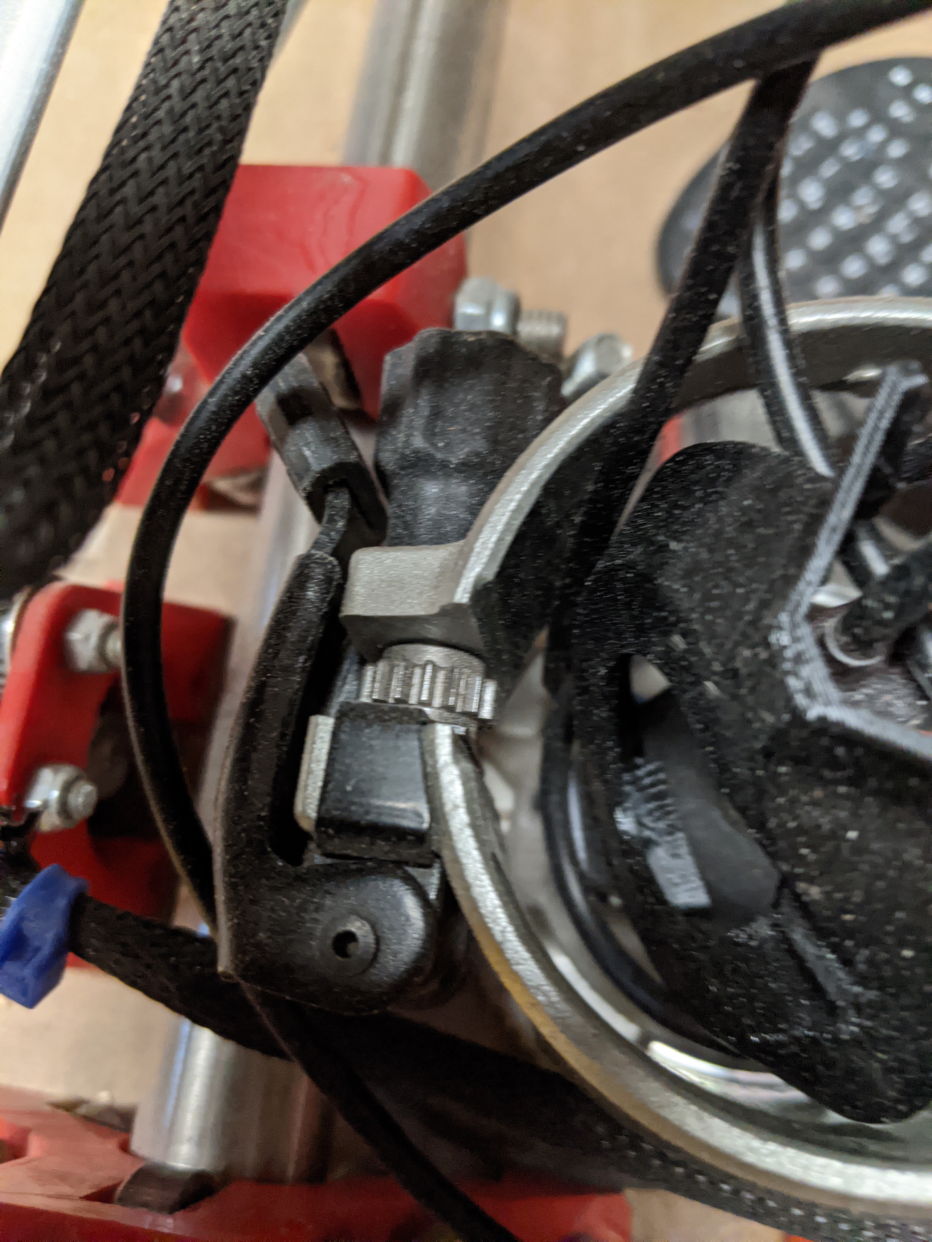
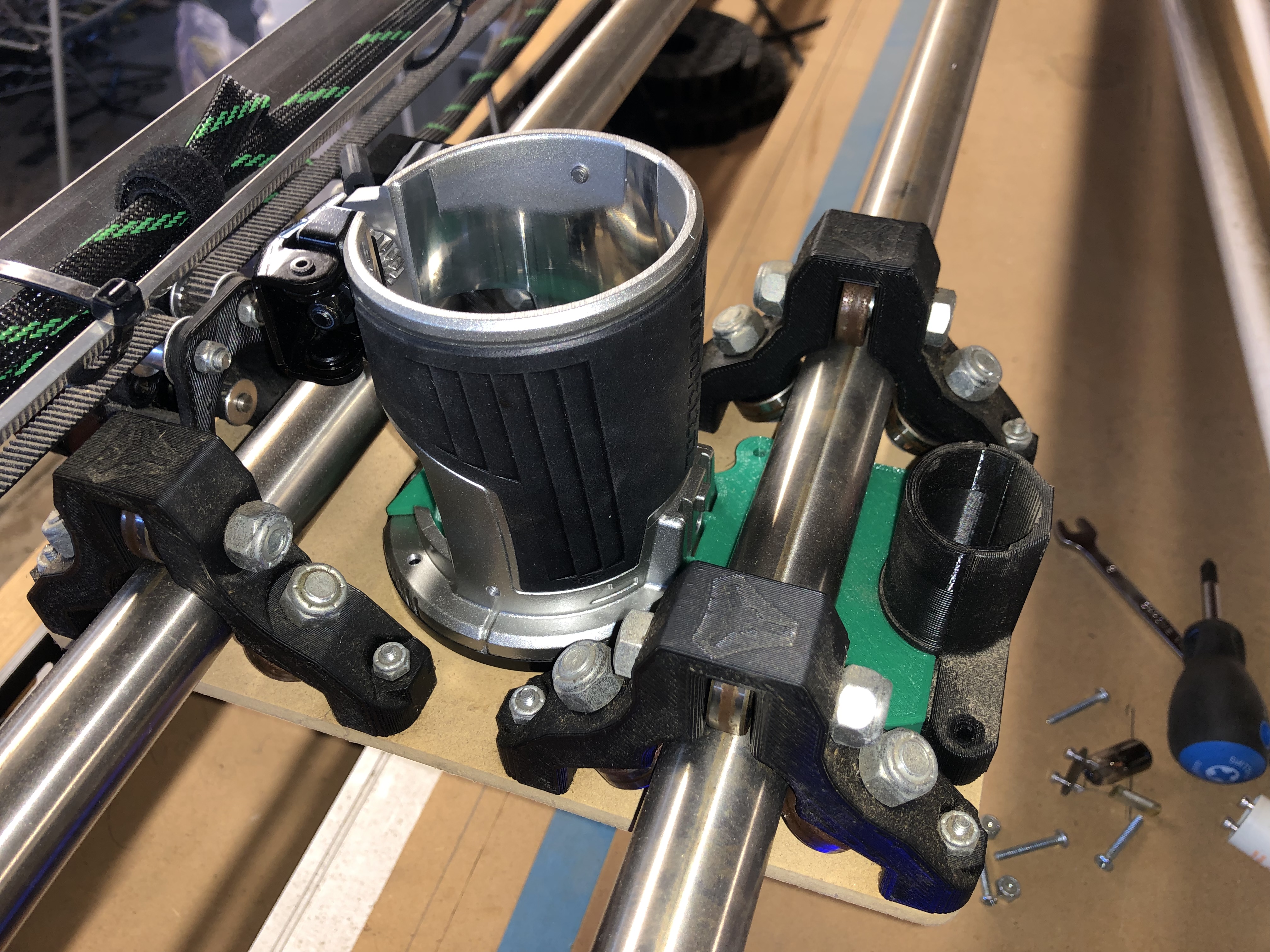
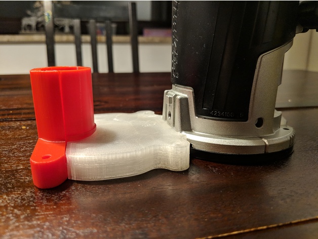
This is how it sits now, with the clamp facing the vacuum rail.
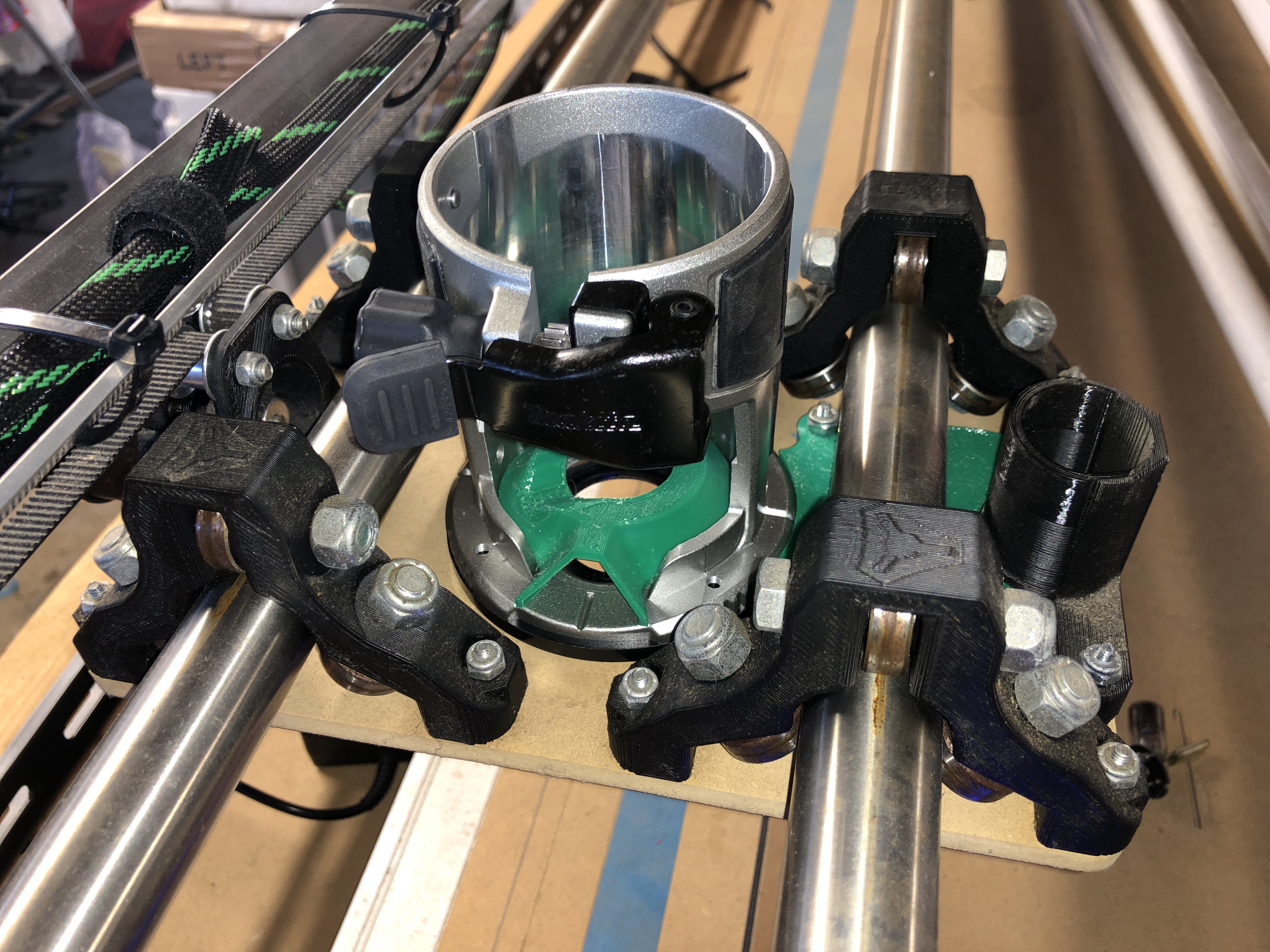
And this is how the new part allows it to sit… so, is there any reason why this would be considered less stable or just incorrect?
Hopefully this was a bit clearer.
Cheers.