Hello! I have recently been working on adding a 4th rotary axis to my CNC. I have had success with swapping the 3rd (y) axis with a rotary axis. Now I am trying to add a real 4th axis.
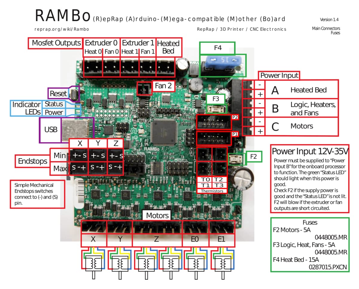
I am using a RAMBO-1.4 currently running the default V1 Marlin Primo firmware. My setup is the normal MPCNC with dual endstops. Because of the already used E0 and E1 motors I want to add an additional motor using the motor extension pins.
I have not been able to find much information online specifically about using the motor extension pins on the RAMBO. I have seen on the V1 forum that a few people, I think, say that using these pins are not possible with the endstops (1, 2). I have looked on the reprap forums but have not been able to find anything. Looking at the RAMBO schematic I don’t see any problems or shared pins. I haven’t been able to read anywhere about shared connections/pins in the Atmega 2560 that would cause problems. Can someone explain what these comments are referring to or what the problems/complications are using the motor extension pins? Or are the comments just saying you will have to add an external driver.
My plan was to use an external motor driver (a4988) to make all of the connections. It looks like you can solder logic vcc, gnd, enable, direction, and step to the driver from MX. Then I would have to solder the main power voltage to the driver. Finally I would connect the 4 stepper motor pins to the driver. Sort of like what’s happening here. Has anyone done this before or can confirm that this is or looks correct?
Ryan and others are saying that it isn’t easy when you are already using all 5 internal drivers. “dual endstop” is what we call the firmware that uses 5 motors and dual endstops for auto squaring. The serial firmware uses only 3 motors, and endstops are pretty pointless, since they don’t do any squaring.
I don’t think any of the pins are shared. There are some non-obvious limitations. For example, the step pin may need to be a PWM capable pin, for example.
That is exactly right. These things need to find connections to pins. I would avoid soldering directly on the rambo.
Here is what I would recommend:
This is your pins file. It has the pins chosen for X, Y, Z, E0, E1. The dual driver configuration (in configuration_adv.h) makes Marlin choose E0 for X2 and E1 for Y2. You either have to define pins for an E2 port, or an I port.
You know about the schematic. My first guess is that disabling the screen would give you a lot of pins you could use for an external driver. Stuff like heaters and thermistors might have annoying circuitry attached. You might be able to use the endstop sense pins, but you probably already have endstops on them. There are a few other headers, but I am not familiar enough to know if they work. You can change the output of any pin with M42.
You need to configure an A axis. I haven’t done this. But it looks relatively supported.
You need to figure out the CAM. Maybe you already know how to generate gcode in 4dims.
Showing your rotational work really gives me hope you will break through and figure this out.
Don’t forget to tune the current limiting potentiometer on your a4498. They aren’t tuned at the factory.
Yeah, I am running 5 motors and I use the “dual endstops” for homing/squaring. I was a bit confused especially by this comment just about if it was in fact possible to keep my current setup while adding a motor extension.
I see, these are the sort of things that I was worried about and keep me up at night . I’m hoping that the dedicated motor extension pins on the RAMBO 1.4a were well designed and will work.
Thank you. I will look more into the firmware side. I’m not too familiar with Marlin and I’m a little nervous to reflash my board when the time comes. Besides mapping pins and defining an A axis is there anything else that I really need to do? What file would I edit to add an option to manual move the new axis from my LCD display?
Yeah I was thinking using other unused pins as worst case thing, I could even drop the enable pin on the stepper I think if I need. Is there any reason why I would need to scavenge for pins or unplug the LCD though? The motor extensions should work?
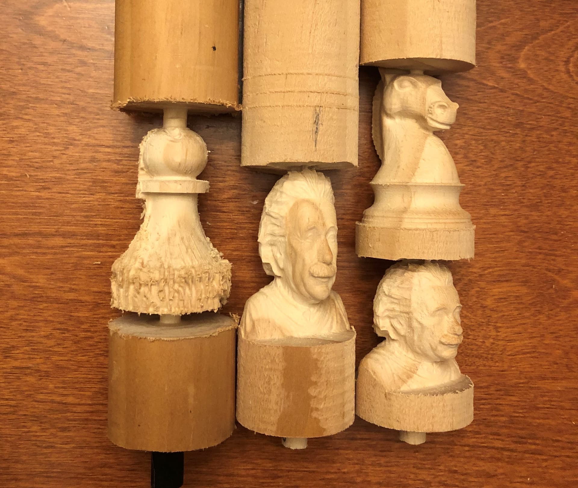
I have been working on CAM since that seems to be the slightly harder part. So far I have done the schorchworks method, I have also made my own method using blender and fusion (without the expensive 4-axis machining extension) for more complicated objects like what my picture in post #1 shows. I also want to try to use HSMworks in solidworks. I hope to put out an instructable or something showing these methods off.
These methods are still mainly focused 3-axis gcode but remapped to the rotary axis. I hope that I can either manually add rotational 4th axis commands into the gcode or get hsmworks running. To be honest I mainly want to enable the 4th axis just to not have to switch the pins each time I want to change from conventional 3-axis to rotary 3-axis. It would also be nice to have the y-axis motors engaged during cutting so they don’t move around (currently I have to unplug them).
Haha I have burnt out 4 of these already. Good thing they’re cheap!
I am still mainly surprised at the lack of documentation and user posts about these MX pins on the RAMBO. It makes me think something may be wrong Any more thoughts or concerns would be greatly appreciated!
Yeah that is all oversimplifying. Most people would not easily understand adding another driver externally, and changing the pins file, recompiling.
Most people never needed more than 4 drivers when that board was in it’s prime. Since the 6-8 driver configs are coming out most have long since moved to 32 bit boards. As far as I know all three breakouts work and are setup for steppers. We used to use one for lasers (pwm).
Many thanks, it is reassuring to hear that it will hopefully work. That’s understandable, I also definitely wasn’t ever expecting to ever need more than 5 drivers! I guess that’s just one con for using a RAMBO with the dual endstop setup.
Not yet, I’m hoping to make some sort of video or written documentation about the whole process. I do have a video that may give you and idea of what my rotary 3-axis blender/fusion CAM method looks like if you’re curious and want a sneak peek
This might not make sense out of context, but if you understand some of the CAM struggles of remapping a linear axis to rotary hopefully it will help. I will explain it more in the future
I am not sure. I have never done it. I would not be surprised if the lcd just worked. I can’t give you an exhaustive list. But there are some sanity checks in the marlin build. It may complain if you are missing something. It is really hard to break anything with the firmware. So feel free to take small steps and see what happens. Make sure you build the code without changing anything first (and maybe flash the board to make sure the vanilla setup works, which we have a lot of experience with). Then compile regularly while making changes. If you can find a guide somewhere for how to configure any board to use the A axis, that would be more helpful.
I have to go look at the schematic again. I didn’t know there were pins dedicated to that. There isn’t a E2 defined in the pins file.
You can get a 4 pole double throw switch, which will switch 4 outputs to two places and wire it all up together. It isn’t as cool and you never want to throw the switch while enabled. But it would be a lot easier.
If you ditch the LCD you might be able to use EXP1 and EXP2 for a BTT Motor expansion.
For the SKR boards the motor expansion option is defined in the pins file and can be enabled just by defining BTT_MOTOR_EXPANSION. The Rambo does not include this option so you would have to add the pins definition yourself. I am not 100% sure if this would work but there is a good chance it would work if you just copy the PINS definition from one of the SKR boards:
SKR 2.0 defines the expansion for E2, E3, E4
SKR Pro defines the expansion for E3, E4, and E5
SKR Octopus defines the expansion for E4, E5, and E6
I picked the SKR 2.0 above because Rambo defines E0 and E1 but not E2 or higher.
I think this would enable software current control on say TMC2209 using serial communication. It would sure save a lot of soldering.
Since this occupies EXP1 and EXP2, you wouldn’t be able to use the LCD anymore, meaning you need to drive the machine using the USB from a laptop or Raspberry Pi.
Many great things to think about. I think my main options are to:
Somehow get misc pins to work to run an external motor driver. Change the firmware too
Keep it at 3-axis and toggle between y and rotary (thanks @jeffeb3 for the 4 pole double throw switch idea)
Drop the LCD and run an external motor driver (thanks @jamiek for sharing the breakout board)
Get a whole new board with more pinouts?
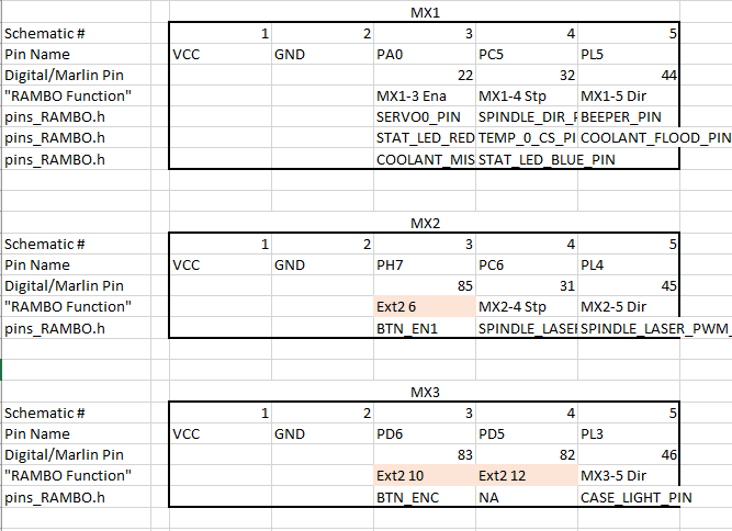
I am still shooting for #1 but we’ll see what happens. After looking a bit more it seems more complicated than I expected pin-wise. I have made a small lineup of the MX pins on the RAMBO that is below. This is just pulling from the schematic, the pins list, and the pins_RAMBO.h file.
This makes me way more confused than before. Here are some questions I have for anyone who might know.
How are pins defined in the pins.h file as multiple things. For example the 3rd MX1 pin is being defined as for servos, coolant, and an LED. I would think defining multiple functions to one pin would make a conflict. (The LED may not actually be defined because I’m not using one of those displays)(I don’t use coolant or servos)
Why are some of the motor extension pins said to be general (display) extension pins? I have highlighted them in red. The MX2 3rd pin for example is said to be on one of the endstop pins. Is it possible the schematic or more likely the pins chart is wrong?
For additional confusion on question 2 above- all of the highlighted red MX pins are only defined for the “VIKI2 or miniVIKI” boards in the pins.h file. If they were really “Ext” pins as the pins list showed wouldn’t they be used currently and be defined currently for the LCD screen that I am using?
Is the pin list that I am referring to accurate and meant for the RAMBO 1.4?
It is all very confusing but the main point is that I am wondering which pins I should use, it seems like I can choose any assortment of 3 of the 9 data pins. Although all but one are defined it seems like I am not using any of them currently and could just switch (or add?) a definition. Any advice on which pins to use/avoid would be appreciated too.
Not all those things are enabled at once, or at all.
MX1 was almost never used as a stepper driver, MX2-3 were probably never used as stepper drivers. The firmware gets setup by whomever needs it. If we submitted a pull request for a new screen we could use any pins we wanted provided it did not cause a compile error for a standard 3 stepper 3d printer. I think you just need to define those three pins and be done. (PS Servo pins are PWM)
If you have not enabled the obscure viki screen then no those pins are not doing anything.
Yes, the rambo all have the same pinout, they just moved the pins so we did not need the daughter board after 1.3, the pins are still the same, they physically just moved a bit.
These definitions don’t do anything in the code by themselves. Defining SERVO_PIN doesn’t do anything until you enable the servo code with something like #define BL_TOUCH.
There are also a lot of sanity checks w.r.t. the pins. If you manage to use the same pin for x endstop and y endstop, then Marlin will check that at compile time and give you an error, refusing to build the code.
Gotcha, thank you both for explaining. In retrospect this makes sense.
When I compile the firmware in VS with platformio (without making any changes) I get some warnings just like expressed in this post. I guess it’s not a big deal but why aren’t those resolved in the final v1 firmware? Or is it my fault?
Do I want my pins for the motor extension to be defined as for the “I” or “A” motor in the pins file? I find it a little confusing that they the non-X/Y/Z axies have two names. I think “I” is the name I should use and “A” is just the name it is mapped to for gcode commands but correct me if I am wrong.
Random question but why are the motor drivers defined in marlin as a4988 when it says on the schematic that they are a4982? Is a4982 not an option? I see that a4982 only have two micro-stepping pins so they are at least slightly different from each other.
Here is everything I added/changed with the firmware- all in the config, advanced config, or pins files. I just followed the chain of errors, which was surprisingly easy to do It seems to have built so I hope to try and flash it at the end of the week!
A lot of the errors had to do with homing which is a shame because I never plan to using homing on a rotary axis. It looks like it may be possible to not have to set up homing by just removing some of the sanity checks, but that sounds a bit risky. I reused the X_MIN_PIN number for the I_MIN_PIN, is this a bad idea?
You have both mentioned PWM pins in your posts, do you know that nema/a4988 need PWM pins? I have not been able to find anywhere that this is the case. Maybe some of the fancier drivers need PWM pins?
Additionally the schematic has pwm in green (or just green labels) on some of the pins. However, none of the existing motor drivers (a4982) seem to be using them.
STEP (and DIR and ENABLE) do not need the PWM function.
The firmware bangs out each step at a precise time and counts the number of steps, whereas PWM allows setting a value once and letting it automatically generate a series of pulses with no intervention. That kind of asynchronous PWM makes sense for servo position and laser intensity where it is a way to communicate what is effectively an analog value and the individual pulses are not significant. For motor position the controller needs tight control over the number of pulses and their timing, so PWM is not used, even if it is available.
This is saying that X2 is automatically being assigned to E0. It used to be that was the only way to do it. We have figured out that system in our config system. We could change to explicitly renaming the E0 to X2, but that involves editing the pins file, which we don’t want to do. We could add the suggested NO_AUTO_ASSIGN_WARNING. But then we don’t see the warnings. The server builds the code, and we only look at them if we also have an error.
If you’re curious, we configure marlin from scratch by script, and then have the server build the code and upload the compiled firmware. That is done here. Here is an example config for enabling dual on low riders.
You know more than me at this point.
We have had that config since before they considered a difference between a4988 and drv8825. My guess is that the a4988 are the same in terms of timing and input as the a4482. The microstep pins are handled elsewhere. If there is a 4482, then we should switch and try it.
Thank you for the help in this thread @jeffeb3 , @jamiek , and @vicious1, I really appreciate it. I figured it all out in hardware, electronics, and firmware. It’s now a fully functioning REAL 4th axis setup!!! Hopefully I can write something up about that too at some point.
Because I think it’s a pretty different topic I posted the documentation for my original rotary axis setup in a new thread.